
SIEMENS ICROMASTER 420 frequency converter
SIEMENS ICROMASTER 420 frequency converter
Product positioning and core technology
Overview
The operating manual for the Siemens MICROMASTER 420 frequency converter (version B1, order number 6SE6400-5AA00-0BP0) covers its core information in detail: as a frequency converter used to control the speed of three-phase AC motors, the power range ranges from 120W single-phase input to 11kW three-phase input, using IGBT technology and multiple V/f control modes; The content includes equipment overview, installation (including mechanical/electrical installation requirements such as capacitor restructuring and grounding specifications), debugging (supporting SDP/BOP/AOP panels, including quick debugging process), parameter system (level 4 user access, key parameters such as P0010 quick debugging and P0970 factory reset), troubleshooting (fault codes and LED indicators), technical specifications (such as input voltage of 200-480V ± 10%, output frequency of 0-650Hz), and EMC compatibility requirements. It also emphasizes that only qualified personnel are allowed to operate, and clarifies various safety warnings (such as waiting for 5 minutes for discharge after power failure).
Function: Control the speed of three-phase AC motors, with a power range covering 120W (single-phase input) to 11kW (three-phase input).
Technology: Adopting IGBT (Insulated Gate Bipolar Transistor) technology, supporting PWM modulation with optional pulse frequency (to achieve low-noise motor operation), and the core control is based on V/f mode.
Installation specifications (mechanical+electrical)
1. Preparation before installation
Requirements for capacitor restructuring (after long-term storage):
Storage duration operation requirements
No operation required for<1 year
Power on for 1 hour after 1-2 years before resuming use
Reorganize according to the voltage time curve for ≥ 2 years (e.g. 2 hours for 100% voltage)
Environmental conditions:
Temperature: Operating -10~50 ℃, Storage -40~70 ℃;
Humidity: ≤ 95% (no condensation);
Altitude: ≤ 1000m without capacity reduction, over 1000m requires capacity reduction (e.g. output current drops to 80% at 2000m);
Protection: Avoid vibration (in accordance with DIN IEC 68-2-6, acceleration ≤ 9.8m/s ²), electromagnetic radiation, dust/corrosive gases, and water hazards.
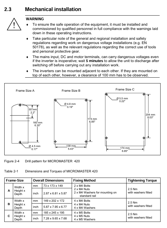
2. Mechanical installation
Installation method: Only vertical installation is allowed, A frame (low power) can adapt to 35mm standard guide rail (EN 50022), B/C frame requires bolt fixation.
Spacing and dimensions:
Frame dimensions Overall dimensions (width x height x depth) mm Tightening method Tightening torque Installation gap
A 73 × 173 × 149 2 M4 bolts/nuts+washers 2.5Nm (with washers), 100mm up and down, with no gap on both sides
B 149 × 202 × 172 4 M4 bolts/nuts+washers 2.5Nm (with washers), 100mm up and down, with no gap on both sides
C 185 × 245 × 195 4 M5 bolts/nuts+washers 2.5Nm (with washers), 100mm up and down, with no gap on both sides
3. Electrical installation (core safety requirements)
Grounding: It must be grounded according to the IEC 536 Class 1 standard, and the PE wire section should not be smaller than the power wire to avoid the risk of electric shock; The reference voltage for motor grounding should be consistent with the ground voltage.
Power and motor wiring:
Input terminals: single-phase (L/L1, N/L2), three-phase (L1, L2, L3); Motor terminals (U, V, W), DC terminals (DC+, DC -);
Power outage requirement: Wait for 5 minutes after power outage before opening the cover (discharge of DC bus capacitor). The terminal may still carry dangerous voltage after power outage.
Special scenario configuration:
Scene configuration requirements
IT power supply (ungrounded): Remove the internal "Y" capacitor (see Appendix D/E) and install the output reactor; When the output is grounded, the frequency converter trips (F0001)
The use of RCD requires the selection of B-type RCD, with a trip limit of 300mA, neutral grounding, and only one frequency converter for a single RCD. The motor cable should be ≤ 50m (shielded)/100m (unshielded)
Long cable motor cable ≤ 50m (shielded)/100m (unshielded), special configuration required for over distance
EMI protection: Power cables (power+motor) and control cables are wired separately (in different cable trays/conduits), motor cables are shielded/armored and grounded at both ends, and contactor coils require R-C suppressors (AC) or freewheeling diodes (DC).
Debugging process and operation
1. Operation panel selection and configuration
SDP (Status Display Panel): default configuration, 2 LEDs (green/yellow) display operating status (such as "green+yellow constant light=ready" and "red light flashing for 0.3s=overcurrent"), compatible with motor rated parameters (power, voltage, current, frequency), default control: analog potentiometer frequency modulation rate (0-10V corresponds to 0-50/60Hz), ramp time 10s.
BOP (Basic Operation Panel): Optional accessory, 5-digit 7-segment display, requires parameter activation:
Enable control: set P0700=1 (instruction source is BOP), P1000=1 (frequency given as BOP);
Core button functions:
Key Function Remarks
The start button is disabled by default for starting the motor, and P0700=1 is required to enable it
Press and hold the stop button OFF1 (slope stop)/OFF2 (free stop) twice or once to keep it enabled
When the reverse button switches the motor direction to reverse, it displays a "-" or flashes a decimal point
Fn key to view additional information (DC bus voltage, output current, etc.) Short press to jump to r0000, long press to cycle display status
AOP (Advanced Operating Panel): Optional accessories, supporting multiple languages, parameter upload/download, and multi machine (30 units) control. Please refer to the AOP independent manual.
2. Quick debugging (key process)
Enter debugging mode: set P0010=1 (fast debugging filtering);
Basic configuration:
P0700: Select instruction source (e.g. 1=BOP, 2=numeric input);
P1000: Select frequency given (e.g. 1=BOP, 2=analog input);
P0100: Select region (0=Europe 50Hz/kW, 1=North America 60Hz/hp);
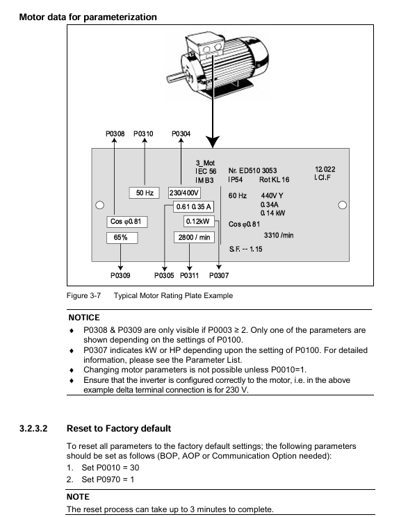
Motor parameter settings (matching motor nameplate):
P0304: Rated voltage of motor (V);
P0305: Rated current of motor (A);
P0307: Rated power of motor (kW/hp, determined by P0100);
P0310: Rated frequency of motor (Hz);
P0311: Rated speed of motor (rpm);
End debugging: Set P3900=2 (perform motor calculation+restore P0010=0), and it can be run after completion.
3. Factory reset
Operation: Set P0010=30 (reset filter) → P0970=1 (trigger reset), the reset process takes about 3 minutes, and the parameters will return to factory default after reset.
4、 Detailed Explanation of Parameter System
1. Parameter access control
Access level (P0003): Level 4 permission, determining the visible parameter range:
1 (Standard): Basic operating parameters;
2 (Extension): Add motor and control related parameters;
3 (Expert): Add advanced debugging parameters;
4 (Service): Hidden parameters (requires P3950=1 to unlock).
Parameter filtering (P0004): grouped by function for quick search:
P0004 value function grouping includes parameter examples
2 frequency converter units r0026 (DC bus voltage), P1800 (switching frequency)
Motor data P0304 (rated voltage), P0610 (motor I ² t protection)
7 Instructions and Digital I/O P0700 (Command Source), P0731 (Digital Output)
10 Frequency Given and Slope P1000 (Frequency Given), P1120 (Slope Rise Time)
2. Classification of core parameters
Parameter Category Key Parameter Function Description Default Values (Europe)
Debugging Control P0010 Debugging Mode Filter 0 (Normal)
P3900 ends debugging 0 (without performing motor calculations)
P0970 Factory reset 0 (not triggered)
Motor protection P0610 motor I ² t protection 2 (enabled)
P0335 motor cooling method 0 (self cooling)
Operation control P1300 control mode 1 (linear V/f with FCC)
P1120 Slope Rise Time 10s
P1121 Slope descent time 10s
Troubleshooting and Warning
1. Fault indication method
SDP: Fault is determined by the combination of on/off/flashing of two LEDs (such as "dual lights flashing together=ROM fault" and "dual lights flashing alternately=RAM fault"), as shown in Table 6-1.
BOP/AOP: Display fault codes (Fxxx) or alarm codes (Axxx), and view historical faults (P0947 stores the last 8 faults).
2. Common faults and solutions
Fault code, fault type, possible causes, and solutions
F0001 grounding fault 1. The motor power does not match the frequency converter; 2. Motor/cable grounding; 3. Motor overload: 1. Check the power between P0307 and the frequency converter; 2. Check the insulation of motor windings/cables; 3. Reduce load
F0002 DC bus overvoltage 1. Input voltage too high; 2. The slope descent time is too short; 3. The regenerative energy of the load is high. 1. Check the power supply voltage (which should be between 200-480V ± 10%); 2. Increase P1121 (slope descent time); 3. Install a braking unit
F0051 parameter EEPROM fault EEPROM read/write failure 1. Perform factory reset (P0010=30+P0970=1); 2. Replace the frequency converter (if reset is ineffective)
3. Fault reset method
Power off and restart the frequency converter;
Press the reset button on BOP/AOP;
Triggered by digital input 3 (default function is fault reset).
Technical specifications and certification
1. Core electrical specifications
Project specification parameters
Input voltage: 1 phase 200-240V ± 10%, 3 phases 200-240V ± 10%, 3 phases 380-480V ± 10%
Input frequency 47-63Hz
Output frequency 0-650Hz
Overload capacity 50% overload (60s/5min, based on rated output current)
Efficiency 96-97%
Control mode linear V/f (P1300=0), linear V/f with FCC (P1300=1), secondary V/f (P1300=2), multi-point V/f (P1300=3)
Interface: 3 digital inputs, 1 analog input (0-10V), 1 relay output, 1 analog output (0-20mA), RS485 communication
2. Certification and Compliance
Protection level: IP20;
Certification standards: UL, cUL, CE, C-tick;
Directive Compliance: Compliant with EMC Directive 89/336/EEC and Low Voltage Directive 73/23/EEC;
EMC classification: Supports Class 1 (industrial general), Class 2 (filtering industry), Class 3 (civil/commercial/light industry, requiring Class B filters).
Optional accessories
Accessory type, specific product function
Equipment independent accessory BOP (basic operation panel) basic parameter setting and operation control
AOP (Advanced Operating Panel) with multiple languages, parameter upload/download, and multi machine control
PROFIBUS module realizes PROFIBUS communication
PC Connection Kit PC and Inverter/AOP Connection
DriveMonitor/STARTER PC Debugging Tool
The equipment relies on accessories such as EMC filters (Class A/B) to reduce electromagnetic radiation and comply with different EMC levels
Input/output reactors suppress harmonics and protect frequency converters (necessary for IT power supply)
The wiring board facilitates cable connection and shielding
Safety Warning (Core Emphasis)
Personnel qualifications: Only "qualified personnel" are allowed to operate (training is required for circuit switching, use of protective equipment, and first aid skills);
Voltage risk: Do not open the cover (capacitor discharge) within 5 minutes after power failure, and dangerous voltage may still be present after input/motor/DC terminals are powered off;
Prohibition of substitution: cannot be used as an "emergency stop device" (requires separate configuration of emergency stop devices that comply with EN 60204);
Motor protection: The motor parameters (P0304/P0305, etc.) must be accurately configured, otherwise the motor overload protection will fail
- OMRON
- ABB
- General Electric
- EMERSON
- Honeywell
- HIMA
- ALSTOM
- Rolls-Royce
- MOTOROLA
- Rockwell
- Siemens
- Woodward
- YOKOGAWA
- FOXBORO
- KOLLMORGEN
- MOOG
- KB
- YAMAHA
- BENDER
- TEKTRONIX
- Westinghouse
- AMAT
- AB
- XYCOM
- Yaskawa
- B&R
- Schneider
- KONGSBERG
- NI
- WATLOW
- ProSoft
- SEW
- ADVANCED
- Reliance
- TRICONEX
- METSO
- MAN
- Advantest
- STUDER
- DANAHER MOTION
- Bently
- Galil
- EATON
- MOLEX
- DEIF
- B&W
- ZYGO
- Aerotech
- DANFOSS
- Beijer
- Moxa
- Rexroth
- Johnson
- WAGO
- TOSHIBA
- BMCM
- SMC
- HITACHI
- HIRSCHMANN
- Application field
- XP POWER
- CTI
- TRICON
- STOBER
- Thinklogical
- Horner Automation
- Meggitt
- Fanuc
- Baldor
- SHINKAWA
- Other Brands
- UniOP
- KUKA
- Iba
- Beckhoff
- ADLINK
-
 Basler Electric BE1-700 Digital Protective Relay
 -
 Basler Electric SR8A-2B01B3A Static Voltage Regulator
 -
 Basler Electric SR4A-2B01B3E Static Voltage Regulator
 -
 Basler Electric 9017709102 PC Board
 -
Basler Electric SR4A-2B01B3A Static Voltage Regulator
-
 Basler Electric PRS-250 Veri-Sync Relay
 -
 Basler Electric 9066800102 Excitation Support System
 -
 Basler Electric BE1-87G Generator Differential Relay 9 1708 18 100
 -
 Basler Electric 36T865-2 BE03752001 Power Supply
 -
 Basler Electric M-300 149D940G02 Power Supply
 -
 Basler Electric ACA2040-25GM 4Mp 25Fps Area Scan Camera
 -
 Basler BE1-87G-S1A-A1C-A0N0 Differential Relay
 -
 Basler SR8A-2B06B3E Static Regulator SR8A2B06B3E
 -
 Basler SCP-210 Frequency Controller 9095400100
 -
 Basler BE1-59-A3E-A1J-N1N3F Overvoltage Relay BE159A3EA1JN1N3F
 -
 Basler 9 2011 11 100 Bracket Mounted Terminal Unit
 -
Basler 9 1606 00 101 Voltage Regulator
-
 Basler CBS-377 Current Boost System 9109600102
 -
 Basler 8650C72 Exciter Control Module PCB Rev 5
 -
 Basler C2EE1PA0N1F BE1-32R Reverse Power Relay
 -
 ADLINK HPCI-14S12U - Industrial Control Backplane 12PCI Backplane PCI-14S Passive Backplane
 -
-0010.png) ADLINK PCIe-GIE74C - image acquisition card 4-CH GigE Vision PoE+ Frame Grabber
ADLINK PCIe-GIE74C - image acquisition card 4-CH GigE Vision PoE+ Frame Grabber -
-0010_1.png) ADLINK PCI-8164 - control card 4-Axis Advanced Motion Controller Board
ADLINK PCI-8164 - control card 4-Axis Advanced Motion Controller Board -
 ADLINK PCIe-U304 - 4 Port USB3 PCIe Frame Grabbers USB Screw Hole Card
 -
 ADLINK PCI-9112 - Multi-Function Data Acquisition Card DAQ Card
 -
 ADLINK PCI-7432 - 51-12013-0A50 4-CH Isolated Numérique I/O PCI Cartes Digital I/O Card
 -
 ADLINK PCA-6106P3-0C1 REV.C1 - backplane 6-Slot Passive Backplane Board
 -
 ADLINK PCI-7224 - 24-CH Opto-Isolated Digital I/O PCI Board
 -
 ADLINK CPCI-7433R(G) - Digital Input Board Rear I/O CompactPCI Card
 -
 ADLINK EBP-13E4 - 51-46703-0A30 Industrial PC Backplane Passive Backplane
 -
 ADLINK PCIE-HDV62 - Image acquisition card High Definition Video Frame Grabber
 -
 ADLINK EBP-13E4 - 51-46703-0A30 Industrial Backplane Board Passive Backplane
 -
 ADLINK 90111-B1 / CPCI-6770 - PCB CPU MODULE CompactPCI Single Board Computer
 -
 ADLINK PCI-7248 - DATA ACQUISITION PCI CARD 48-CH Parallel Digital I/O Board
 -
 ADLINK PCI-7230 - 51-12003-0a50 board PCI7230 32-CH Isolated Digital I/O Card
 -
 ADLINK PCI2A000CB - 51-20000-0B30 Multi-Function DAQ Card Baseboard
 -
 ADLINK PCI-8134-005 - 4-Axis Motion Controller Card
 -
 ADLINK PCI-7224 - 24-CH Opto-Isolated Digital I/O PCI Card
 -
 ADLINK PCI-7434 - 64-CH Isolated Digital Output Card
 -
 ADLINK PCI-8132 - motion control card 2-Axis Servo & Stepper Controller
 -
 ADLINK PCI-8134 - Motion Controller PCI Card 4-Axis Controller Board
 -
 ADLINK PCI-8164 - Motion Control Card 51-12406-0A40 4-Axis Controller
 -
 ADLINK 51-12001-0C20 - Circuit Board Data Acquisition Interface Module Hardware
 -
 ADLINK NuPR0-840 - industrial control motherboard Full-Size PICMG CPU Board
 -
 ADLINK PCI-7444 - 51-12023-0A10 card 128-CH Isolated Digital Output Board
 -
 ADLINK PCI-1612B - data acquisition card 4-Port RS-232/422/485 Serial Communication Card
 -
 ADLINK PCI-6208V 009 - 8/16-CH 16-Bit Analog Output Cards PCB-I-E-482=6BX3
 -
 ADLINK NUPRO-935A/LV - industrial control motherboard Full-Size PICMG SBC Board
 -
 ADLINK PCI-9114DG - Multi-Function DAQ Card Data Acquisition PCI Card
 -
 ADLINK ACL-7130 - Data acquisition card Isolated Digital I/O Board
 -
 ADLINK ABX-6300D-4E1-BP - board ABX6300D4E1BP Video Interface Expansion Card
 -
 ADLINK CPCI-6940 - CPCI-6940/D1539/M16-0(EA)-000E 6U CompactPCI Processor Board
 -
 ADLINK NuPRO-760 - industrial control motherboard Half-Size PICMG SBC CPU Board
 -
 ADLINK IMB-M42H (G)-0020 - industrial control motherboard LGA1155 Micro-ATX Mainboard
 -
 ADLINK RTV-24 / PCI-MP4S - 51-12519-1C30 4-Channel Real Time Video Capture Board
 -
 ADLINK PCI-8134 - 4-Axis Servo & Stepper Motion Controller Card
 -
 ADLINK MXC-6101D - V.PC000.002.ST.00 Box PC Configurable Embedded Computer
 -
.png) ADLINK PCI-8134A - 51-12421-0A10 Motion Control Card 4-Axis Controller Card
ADLINK PCI-8134A - 51-12421-0A10 Motion Control Card 4-Axis Controller Card -
 ADLINK DIN-100S / DIN-100SA1 - Technology SCSI-II TB 100-PIN Terminal Block Board
 -
.png) ADLINK DIN-812M001 / DIN812M001 - 51-14034-0A1 51140340A1 Terminal Module Breakout Interface
ADLINK DIN-812M001 / DIN812M001 - 51-14034-0A1 51140340A1 Terminal Module Breakout Interface -
_1.png) ADLINK PCI-8164 - Servo motion control 4-Axis Advanced Controller Card
ADLINK PCI-8164 - Servo motion control 4-Axis Advanced Controller Card -
 ADLINK PCIe-GIE64 - Acquisition card GigE Vision PoE+ Frame Grabber
 -
 ADLINK M-302 - Industrial control motherboard ATX PC Board Mainboard
 -
 ADLINK PCI-8134 - Motion Controller PCI Card 4-Axis Controller Board
 -
 ADLINK PCI-RTV24 - Image capture card Analog Video Frame Grabber
 -
 ADLINK PCI-8102 - Motion control card 2-Axis Servo & Stepper Controller Board
 -
 ADLINK PCI-9112 REV.B1 - Card Multi-Function Data Acquisition Card
 -
 ADLINK HSI-DI32-M-N / HSL-TB32-M-DIN - Discrete I/O MODULE Distributed Automation Module System
 -
 ADLINK PCI-7296 - IO card REV.A3 96-CH Parallel Digital I/O Card
 -
-0020.png) ADLINK DIN-814P-A4 / 814Y - terminal board Motion Control Interface Block
ADLINK DIN-814P-A4 / 814Y - terminal board Motion Control Interface Block -
 ADLINK DIN-814P-A4 - 51-14056-0A10 PCB-I-E-2736=ZA01 Screw Terminal Board Breakout
 -
 ADLINK M-322 - motherboard Industrial Control Computer Mainboard
 -
 ADLINK NUPRO-406 REV:B1 - industrial control motherboard Full-Size PICMG CPU Board
 -
 ADLINK AMP-204C - card DSP-Based 4-Axis Advanced Pulse-Train Controller
 -
 ADLINK HPCI14S REV.B1 - industrial computer baseboard 14-Slot Passive Backplane
 -
 ADLINK PCI-7250 - 8-CH Relay Output & 8-CH Isolated DI PCI Card
 -
 ADLINK EBP-13E2 - baseplate Passive Backplane Industrial Computer Chassis Board
 -
 ADLINK LPCI-3488A - PCI-GPIB card 51-12801-0A30 acquisition card IEEE-488 Interface Board
 -
 ADLINK PCI-6216V-GL - 51-12201-0C30 16-CH 16-Bit Voltage Analog Output Card
 -
 ADLINK ACL-8454 - 16-CH Isolated Digital I/O & 4-CH Counter Card
 -
 ADLINK HPCI-9S7U - backplane Passive Backplane Compatible with NuPRO-A301 852 841 842
 -
 ADLINK DAQ-2010-007 - Simultaneous-Sampling Multi-Function Data Acquisition Card
 -
 ADLINK MP-C154 - 51-64205-0A10 Motion Control Card 4-Axis Controller Board
 -
 ADLINK MXE-202/mSSD16B/WiFi-BT - Matrix Rugged I/O Platform Embedded Fanless Computer
 -
 ADLINK CM-920-R-17 - PC/104-Plus Single Board Computer Module Intel Celeron M
 -
 ADLINK PCI-7250 NSMP - 8-CH Relay Output & 8-CH Isolated DI Card
 -
 ADLINK PCI-8164 - 4-Axis Motion Controller PCI Card W/ Cable and Breakout Box
 -
 ADLINK EMX-100 - Ethernet-based 4-axis Motion Controllers Distributed Motion Module
 -
.png) ADLINK PCI-8134A - Press control card 4-Axis Motion Controller Board
ADLINK PCI-8134A - Press control card 4-Axis Motion Controller Board -
 ADLINK M-845EG REV:3.2 - industrial motherboard Pentium 4 Socket 478 Micro-ATX
 -
 ADLINK PCI-9114A Rev A2 DG - card High-Resolution Multi-Function Data Acquisition Board
 -
 ADLINK IEC-915GV - REV 1.1 Industrial motherboard Socket 478 CPU Board
 -
 ADLINK PCI-9111DG(G) - Data Acquisition Card Multi-Function DAQ Card
 -
 ADLINK HPCI-15S10 REV:B2 - Industrial computer base plate Passive Backplane Board
 -
 ADLINK NuPR0-840 / NuPR0-840DV - industrial control motherboard Full-size PICMG CPU Board
 -
 ADLINK RTV-24 / PCI-MP4S - 51-12519-1C30 4-Channel Real Time Video Capture Board
 -
 ADLINK NUPRO-780 - industrial control motherboard Pentium III Single Board Computer
 -
 ADLINK PCI-7296 - 0050 card 96-CH Opto-Isolated Parallel DIO Card Set
 -
-0040.png) ADLINK NUPRO-780 - industrial control motherboard PICMG Full-Size SBC
ADLINK NUPRO-780 - industrial control motherboard PICMG Full-Size SBC -
 ADLINK PCI-7248 - 51-12006-0A3 002 Pci 7248 48-CH Parallel Digital I/O Card
 -
 ADLINK PCI-7230 - 32-CH Isolated Digital I/O Card
 -
 ADLINK AMP-204C - motion control card 4-Axis Advanced Controller Board
 -
.png) ADLINK PCI-1714UL - Card Ultra High-Speed 4-CH Simultaneous Sampling DAQ
ADLINK PCI-1714UL - Card Ultra High-Speed 4-CH Simultaneous Sampling DAQ -
 ADLINK NuPRO-E330 - industrial computer equipment motherboard PICMG 1.3 SHB SBC
 -
 ADLINK AMP-204C - DSP-Based 4-Axis Advanced Pulse-Train Motion Controller Module
 -
 ADLINK PCI-7256 - 001 51-12206-0A2 REV.A2 LPCI-7256 16-CH Latching Relay Output Card
 -
 ADLINK ND6050 - NUDAM DIGITAL I/0 MODULE Distributed I/O Unit
 -
 ASEM BM100 - Box PC Embedded Fanless Industrial Computer
 -
-3650.png) ADLINK PCI-7250 - PCI Acquisition Card 8-CH Relay Output & Isolated DI Board
ADLINK PCI-7250 - PCI Acquisition Card 8-CH Relay Output & Isolated DI Board -
 ADLINK PCI-8164 - Servo motion control 4-Axis Controller Card
 -
 Basler XR2002F Voltage Regulator 9139400101
 -
Basler 2D80367G23 DXCB De-Excitation Module 1200V 5000A
-
Basler SR4A-2B15B3A Static Regulator 120V 50/60Hz
-
 Basler SSR 125-12NF Static Regulator 9 1859 00 106
 -
 Basler BE1-BPR Breaker Protection Relay 9272000315
 -
 Basler SSR 63-12 Static Regulator 9 1859 00 101
 -
 Basler AEM-2020 Analog Expansion Module
 -
 Basler BE 25231-001 Transformer BE25231001
 -
Basler MVC 108 Manual Voltage Control 9037000102
-
 Basler PSS-100-Y5 Power System Stabilizer 0.1-5.0Hz
 -
Basler Electric BE1A-25-M1G-A6T-N4V1F Sync-Check Relay
-
 Basler Electric SR8A2B10B1A Static Voltage Regulator
 -
Basler Electric SR8A2B10B1A Static Voltage Regulator
-
Basler Electric SSR 125-12 Static Voltage Regulator 9185900102
-
 Basler Electric 90-73900-102 Power Supply (Westinghouse 2374A07G03)
 -
 Basler Electric 9400200117 Control Power Unit 12/24VDC 20W
 -
Basler Electric BE1-87G Solid State Generator Differential Relay
-
 Basler Electric BE1-32R Style C3ED1TA0S1F Solid State Protective Relay


