ProSoft Technology ILX56-PBM PROFIBUS DPV1 Master/Slave Module
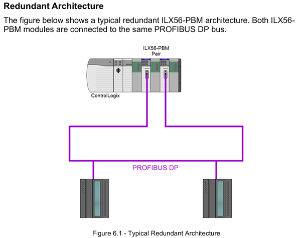
Switch Timeout: The timeout for confirming the primary/backup switch should be set to "Max (1000ms, 4x module RPI)" to avoid switch interruption.

Data interaction and operation
1. Data exchange type
(1) DPV0 cyclic data exchange
Main mode: Interact data with slave devices according to a preset cycle (configurable, minimum 4ms). The input/output data length of each slave device is automatically identified through GSD files, supporting byte/word order exchange (such as AA BB CC DD → BB AA DD CC). In case of communication failure, data can be configured to be forcibly cleared to zero.
From mode: Simulate receiving loop data requests from the PROFIBUS master station, forward ControlLogix output label data to the master station, and write the data issued by the master station to the ControlLogix input label, supporting "Data Exchange Active" status feedback (DataExchange Active label).
(2) DPV1 non cyclic message
Class 1 (MS1): Interacts only with slave devices that have established loop communication in master mode, used for parameter reading and writing (such as modifying slave device range, reading diagnostic registers). The slave address, Slot number, Index number, and data length need to be specified, and the timeout time can be configured (default 4000ms).
Class 2 (MS2): Supports concurrent communication with multiple master stations, requires establishing a connection through "Initialize", obtaining the connection reference number, and performing read and write operations. After the communication ends, a "Abort" message is sent to release resources, suitable for device debugging and parameter configuration.
(3) Alarm and Diagnosis
Alarm collection: Automatically monitor DPV1 alarms from the slave device in main mode, indicating the alarm status through the DeviceAlarmPending tag. Alarm data (such as alarm type, Slot number, detailed description) can be extracted through CIP messages (service code 0x51).
Diagnostic information: Supports standard diagnostics (such as device unresponsive, data length mismatch) and extended diagnostics (device specific diagnostics based on GSD file parsing, such as module failures, wiring errors), which can be viewed or exported in real-time through the PLX50 tool.
Diagnosis and maintenance
1. Status monitoring and LED indication
Meaning of LED light status (main mode) Meaning of status (slave mode)
RUN often red: PROFIBUS STOP mode; Flash green: CLEAR mode; Evergreen: Operational mode; Off: OFFLINE mode is always off (no RUN status indication from mode)
FB flashing red: from device error; Always red: Bus fault (such as cable disconnection); Extinguish: Normal flashing red: Simulate device error; Constant red: Bus communication failure; Extinguish: Normal
OK often red: Hardware malfunction/firmware damage; Flashing green: No configuration; Evergreen: configured normally and running in the same main mode
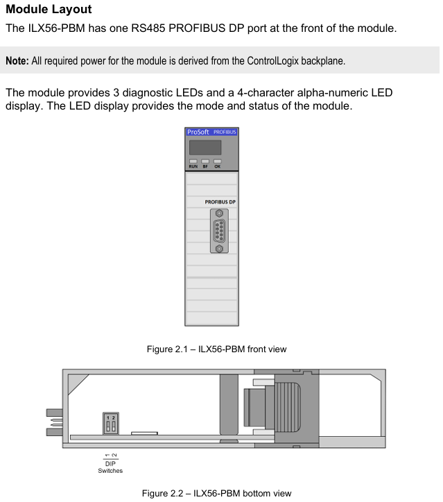
Display screen: display mode ("MASTER"/"SLAVE"), operating status ("OPERATE"/"STOP"), fault code (such as "Duplicate" indicating station address conflict).
2. Tool based diagnostic function
PROFIBUS packet capture: The PLX50 tool supports real-time capture of bus packets, displaying frame types (SD2/SD4), source/destination addresses, data length, and raw data. It can filter specific station addresses or frame types (such as Token frames, SRD data frames) to troubleshoot communication anomalies.
Event log: The module has built-in non-volatile memory to store event logs (such as power on, configuration download, and failover), which can be exported as text files using the PLX50 tool, including timestamps, event types, and detailed descriptions.
Online status monitoring: The PLX50 tool provides a "Live List" to display the real-time online status of all devices on the bus (online/offline, data exchange in progress/not yet exchanged), and the "Discovered Nodes" tab can view device manufacturer, model, and GSD file information.

Technical specifications and compatibility
1. Hardware and environmental specifications
Category parameters
Power supply from ControlLogix backplane: 5VDC 450mA, 24Vdc 2mA
Working temperature -20 ° C~+70 ° C (operation), -40 ° C~+85 ° C (storage)
Electromagnetic compatibility (EMC) emission: IEC 61000-6-4; Immunity: EN 61000-4-2 (ESD), EN 61000-4-3 (radiated immunity)
PROFIBUS supports baud rates of 9.6Kbps~12Mbps, maximum bus lengths of 1200m (9.6Kbps) and 100m (12Mbps), and supports repeater expansion
Certified CE, UL (94V-0 flame retardant), ATEX (II 3G Ex ec IIC T4 Gc), IECEx (same as ATEX)
2. Software compatibility
ControlLogix platform: Supports ControlLogix 1756 series controllers, Studio 5000 v21 and above (AOP required), v20 and below require the use of a universal module configuration file.
Operating system: PLX50 Configuration Utility supports Windows 10/11 (64 bit), firmware upgrade requires the use of SD card or PLX50 tool's DeviceFlash function.
Third party devices: compatible with slave devices that comply with the PROFIBUS DP V0/V1 standard (such as Siemens ET200 series, Schneider Lexium drivers), requiring the import of corresponding GSD files.
- ABB
- General Electric
- EMERSON
- Honeywell
- HIMA
- ALSTOM
- Rolls-Royce
- MOTOROLA
- Rockwell
- Siemens
- Woodward
- YOKOGAWA
- FOXBORO
- KOLLMORGEN
- MOOG
- KB
- YAMAHA
- BENDER
- TEKTRONIX
- Westinghouse
- AMAT
- AB
- XYCOM
- Yaskawa
- B&R
- Schneider
- Kongsberg
- NI
- WATLOW
- ProSoft
- SEW
- ADVANCED
- Reliance
- TRICONEX
- METSO
- MAN
- Advantest
- STUDER
- KONGSBERG
- DANAHER MOTION
- Bently
- Galil
- EATON
- MOLEX
- DEIF
- B&W
- ZYGO
- Aerotech
- DANFOSS
- Beijer
- Moxa
- Rexroth
- Johnson
- WAGO
- TOSHIBA
- BMCM
- SMC
- HITACHI
- HIRSCHMANN
- Application field
- XP POWER
- CTI
- TRICON
- STOBER
- Thinklogical
- Horner Automation
- Meggitt
- Fanuc
- Baldor
- SHINKAWA
- Other Brands


