
BENDER ISOMETER ® Iso685 series
BENDER ISOMETER ® Iso685 series
Product Overview
ISOMETER ® The iso685 series is an integrated insulation monitoring and fault location device developed by Bender, a German company. It is designed specifically for IT systems (ungrounded systems), with the core mission of real-time monitoring of insulation resistance, DC offset voltage, and other parameters. Combined with EDS (Insulation Fault Locator), it achieves accurate fault location and avoids the risk of electric shock and equipment damage. The product is divided into D-type (integrated display/button) and S-type (no display, requiring FP200 panel). The W-enhanced type has higher anti vibration and anti temperature performance (-40~+70 ℃), suitable for complex scenarios such as industrial automation and ship power, and complies with international standards such as IEC 61557-8.
Core parameters and physical characteristics
Category specific parameters
Dimensions: Width 108mm, Height 93mm, Depth 110mm
Weight < 510g (excluding accessories)
Power supply requirements: AC/DC 24~240 V (tolerance -30%~+15%), frequency 50~400 Hz
Environmental adaptability standard type: working -25~+55 ℃, storage -40~+70 ℃; W-type: working -40~+70 ℃
Protection level terminal IP20, internal components IP40
Installation method: DIN rail installation (compliant with IEC 60715), screw installation (3 x M4 screws)
Adaptation system and measurement profile
(1) Scope of adaptation system
System type Voltage range Frequency range Maximum leakage capacitance
AC system 0~690 V (RMS) 0.1~460 Hz 0~1000 μ F (by profile)
DC system 0~1000 V -0~1000 μ F (according to profile)
3 (N) AC system 0~690 V (RMS) 50~60 Hz 0~150 μ F (power circuit profile)
(2) 6 measurement profiles
Profile type applicable scenario key parameters
Conventional constant frequency systems for power circuits measure a voltage of ± 50 V and a leakage capacitance of 0-150 μ F
Control circuits - Low voltage sensitive systems - Measurement voltage ± 10 V, voltage ≤ 230 V
Generator monitoring rapid measurement, frequency 50-60 Hz, leakage capacitance 0-5 μ F
Leakage capacitance of large capacitance systems such as ships with high capacitance ranging from 0 to 1000 μ F
Inverter>10 Hz (Inverter>10 Hz) 10~460 Hz Frequency conversion system leakage capacitance 0~20 μ F
Inverter<10 Hz (0.1~10 Hz) Low frequency system leakage capacitance 0~20 μ F
Detailed explanation of core functions
(1) Insulation monitoring function
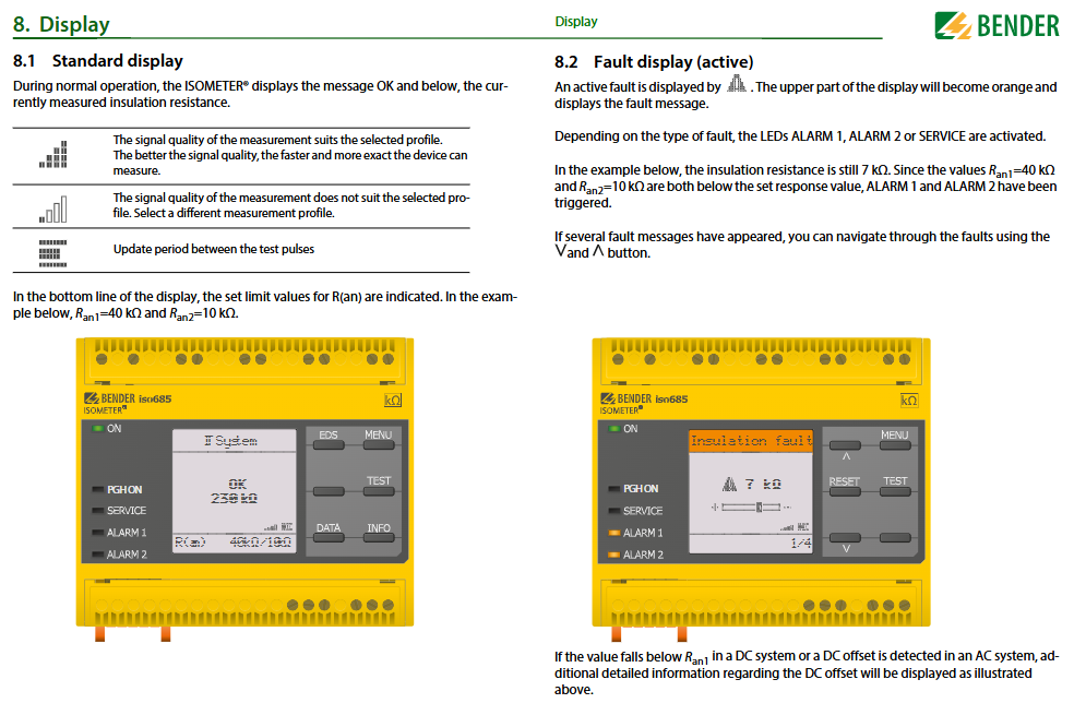
Dual alarm setting: The response values of ALARM1 (warning) and ALARM2 (main alarm) can be independently set between 1 k Ω and 10 M Ω, with default values of 40 k Ω and 10 k Ω, respectively. It supports 25% hysteresis to prevent false alarms.
Connection monitoring: Real time detection of L1/+, L2, L3/- line connections and PE grounding status, triggering sound and light alarms in case of abnormalities.
Data storage: The historical memory can store 1023 alarm/fault information, including date and timestamp, and cache for 3 days after power failure.
IsoGraph trend chart: supports visualization of insulation resistance changes by hour/day/week/month/year, with up to 100 measurement points.
(2) Insulation fault location (EDS function)
Compatible with EDS devices: Supports EDS440-S/L (positioning current 2~10 mA), EDS441-S/L (positioning current 0.2~1 mA), and can connect up to 21 EDSs (255 channels).
Positioning mode:
Manual mode: Continuous positioning, manual stop required;
Automatic mode: ALARM2 triggers and automatically starts, with a cyclic interruption for insulation measurement;
Cycle mode: ALARM2 triggers and starts one cycle before stopping.
Key parameters: The positioning current can be set to 1/1.8/2.5/5/10/25/50 mA, and the response value I Δ L (main alarm) is 200 μ A~10 mA.
(3) ISOnet system isolation
Function: Through Ethernet, multiple devices (≤ 20) can collaborate to ensure that only one device actively measures at a time, while the rest are isolated and in standby mode.
Configuration requirements: BCOM system name and subsystem address should be consistent, device address should be unique, and support automatic skipping of faulty devices.
Interface and Communication
Interface type communication protocol/functional key parameters
Ethernet (ETH) Modbus TCP, BCOM, Web Server 10/100 Mbit/s, up to 5 TCP connections
RS-485 (X1 interface) BS bus, Modbus RTU baud rate 9.6 kBd, transmission distance ≤ 1200 m
X1 multifunctional I/O digital input (3 channels), digital output (2 channels), analog output (1 channel), analog output supports 0~20 mA/0~10 V and other signals
BB bus Bender internal device communication can connect up to 2 EDS44... - S devices without additional power supply
Web server remote parameter setting and data reading support Chrome/Firefox/Edge browsers, with write permission enabled
Operation and debugging process
(1) Basic debugging steps
Equipment installation: Choose the installation method, fix the equipment, and ensure the terminal spacing (horizontal 0mm, up and down 20mm);
Parameter configuration: Set language, date and time, system type, measurement profile, alarm response value, EDS mode, and positioning current through the debugging wizard;
EDS configuration: Scan EDS channel → Activate target channel → Set group parameters (CT type, response value, etc.);
Functional testing: Simulate insulation faults through grounding resistance to verify the accuracy of alarm triggering and fault location;
Operation monitoring: Check the standard display (insulation resistance+signal quality) and trace the data through isoGraph or historical memory.
(2) Alarm and fault handling
Alarm type triggering condition processing method
ALARM1 insulation resistance<Ran1 (default 40 k Ω) Observe the system status and troubleshoot if necessary
ALARM2 insulation resistance<Ran2 (default 10 k Ω), initiate EDS positioning, eliminate the fault, and reset
Check L1/+~L3/- wiring and PE connection for disconnection of faulty circuit or poor grounding of PE
EDS channel malfunction CT connection abnormality or channel not activated Rescan channel, check CT wiring
Maintenance and safety regulations
(1) Daily maintenance
No need for regular oil changes (sealed gearbox), if the cover is opened for maintenance, Mobil needs to be added ® 634 synthetic oil;
Regularly check the BS bus terminal resistance (120 Ω) to ensure stable communication;
Clean the display panel and terminals, ensure clear labeling and stickers, and replace worn parts in a timely manner.
(2) Safety regulations
Only professional personnel are allowed to install and debug. Before operation, the power must be turned off and the system must be confirmed to be out of power;
Power supply requires connection to a 24-240 V GFCI protection circuit, and modification of plugs/cables is prohibited;
When locating faults, avoid positioning current interference with sensitive components (such as PLC), and match the system tolerance value;
Only one device is allowed to actively measure in the coupled IT system, and the rest are isolated through ISOnet or digital input.
Ordering information and accessories
Product Model Description Product Number
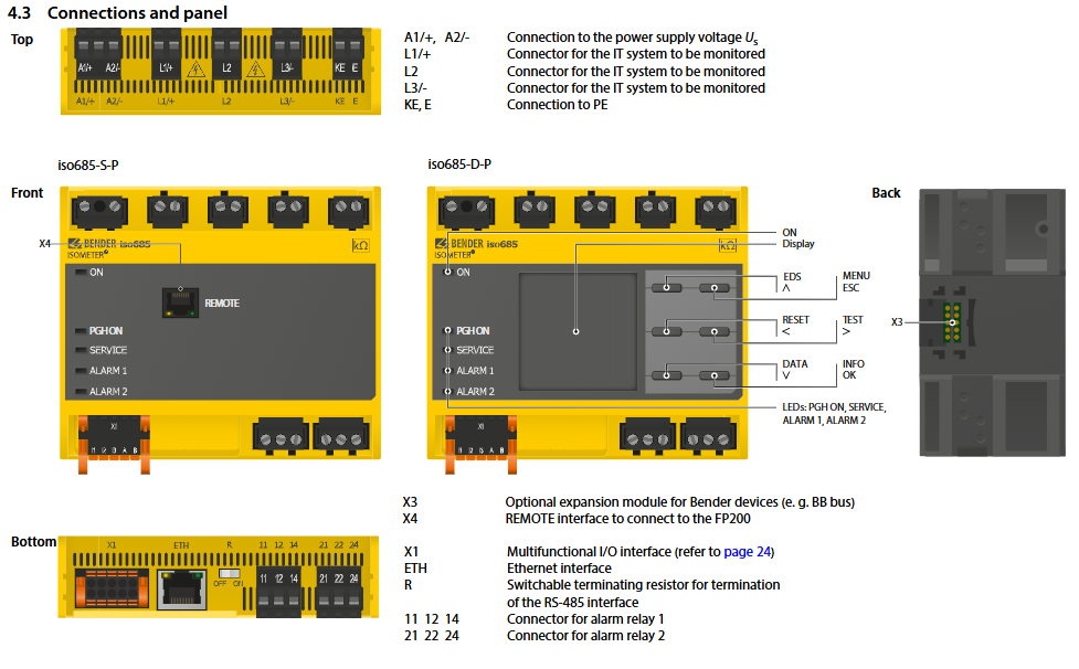
Iso685-D-P with display/buttons, standard B91067030
Iso685W-D-P with display/buttons, W enhanced B91067030W
Iso685-S-P+FP200 without display+panel, standard type B91067230
EDS440-L-4 Insulation Fault Locator (2~10 mA) B91080202
EDS441-S-1 Insulation Fault Locator (0.2~1 mA) B91080204
Mechanical accessory terminal cover+installation clip B91067903
- OMRON
- ABB
- General Electric
- EMERSON
- Honeywell
- HIMA
- ALSTOM
- Rolls-Royce
- MOTOROLA
- Rockwell
- Siemens
- Woodward
- YOKOGAWA
- FOXBORO
- KOLLMORGEN
- MOOG
- KB
- YAMAHA
- BENDER
- TEKTRONIX
- Westinghouse
- AMAT
- AB
- XYCOM
- Yaskawa
- B&R
- Schneider
- KONGSBERG
- NI
- WATLOW
- ProSoft
- SEW
- ADVANCED
- Reliance
- TRICONEX
- METSO
- MAN
- Advantest
- STUDER
- DANAHER MOTION
- Bently
- Galil
- EATON
- MOLEX
- DEIF
- B&W
- ZYGO
- Aerotech
- DANFOSS
- Beijer
- Moxa
- Rexroth
- Johnson
- WAGO
- TOSHIBA
- BMCM
- SMC
- HITACHI
- HIRSCHMANN
- Application field
- XP POWER
- CTI
- TRICON
- STOBER
- Thinklogical
- Horner Automation
- Meggitt
- Fanuc
- Baldor
- SHINKAWA
- Other Brands
- UniOP
- KUKA
- Iba
- Beckhoff
-
 Basler D90 96801 100 PCB Card
 -
 Basler XR2002F Voltage Regulator (110 VAC, 48-480 Hz)
 -
 Basler SR8A-2B14B3A Regulator
 -
 Basler 9561500100 Module
 -
 Basler DECS-400 BE1-11 System
 -
 Basler DECS-100-B15 Excitation Control
 -
 Basler SCP 210 Frequency Controller
 -
 Basler SR4A-2B15B3A Static Voltage Regulator
 -
 Basler BE1-32R Power Relay
 -
 Basler PIA2400-17GM Power Interface Adapter
 -
 Basler MVC 232 Manual Voltage Control Module
 -
 Basler SSR 32-12 Static Voltage Regulator
 -
 Basler 5MW AVR Generator Voltage Regulator
 -
 Basler VR63-4B Voltage Regulator
 -
 Basler DECS-100-A05 AVR for Engine Generator
 -
 Basler DECS-100-B15 Automatic Voltage Regulator
 -
 Basler BE1-32R Directional Power Relay
 -
 Basler BE1-87B Differential Relay
 -
 Basler UFOV 260A Protective Module
 -
 Basler 9-2614-02-100 PCB Rev M
 -
Basler DECS-100-B15 Digital AVR
-
 Basler 9284900103 PS DECS-400N
 -
 Basler D4N3H1U Intertie Protection
 -
 Basler DECS-100-B15 A15 AVR
 -
 Basler KR4F Voltage Regulator
 -
 Basler BE26434 T14 Transformer
 -
 Basler SR8A-2B15B3A Regulator
 -
 Westinghouse 774B472A12 AR Relay
 -
Basler DECS-100-B15 AVR
-
Basler XR2002F Regulator 110V
-
Basler SR125-E Static Regulator
-
 Basler SSR 125-12 Regulator
 -
 Basler MOC2599 Motor Pot
 -
 Basler BE1-DFPR Feeder Relay
 -
 Basler CBS 305 Current Boost
 -
 Basler BE1-25 AutoSync
 -
 Basler MVC 300 Voltage Control
 -
 Basler BE3-25A AutoSync
 -
 Basler KR7FF Static Regulator
 -
 Basler 90-49000-100 Regulator
 -
 Basler 880 kVA Dry Type Transformer Specs
 -
 Basler Electric BE1-25 Sync-Check Relay Specs
 -
 Basler SSR 125-12 Voltage Regulator Specs
 -
 Basler Electric BE1-851 Overcurrent Relay Review
 -
Basler Electric 149D930G02 Control Sub-Assembly
-
 Basler Electric BE1-81O/UT Frequency Relay Specs
 -
 Basler Electric BE1-51/27C Overcurrent Relay
 -
 Basler Electric 149D956G02 Industrial Component
 -
Basler Electric BE1-51A Overcurrent Relay Specs
-
 Basler Electric BE1-40Q Loss of Excitation Relay
 -
 Basler DECS-200 Excitation Control System
 -
 Basler DECS-200 Voltage Regulator 56-277V AC / 125V DC
 -
Basler BE1-87T Transformer Differential Relay
-
 Basler RDP-110-S1 Protection Relay
 -
 Basler BE1-700V Digital Protective Relay
 -
 Basler BE1-951 Overcurrent Protection System
 -
 Basler DECS-300 Digital Excitation Control
 -
 Basler DECS-200 Digital Excitation Control
 -
 Basler DECS-200-1C Excitation Control System
 -
Basler DECS-200-1L Digital Excitation Control
-
 Basler Electric BE1-GPS Generator Protection System
 -
Basler Electric DECS-200-1C Digital Excitation Controller
-
 Basler Electric DECS125-15 Excitation Control with Power Module
 -
 Basler Electric BE1-87G Differential Relay
 -
 Basler Electric BE1-11 Protection System I5A3M2P2N0EA00
 -
Basler Electric DECS-200-1C Excitation Control System
-
Basler Electric BE1-11g Generator Protection Relay
-
Basler Electric DECS 125-15-B2C1 V2.0.9 Excitation Control
-
 Basler Electric BE1-81O/UT3ED1JA7N2F Frequency Relay
 -
Basler Electric BE1-81O/UT3EE1YB7N1F Frequency Relay
-
 Basler Electric DECS-200-1L Digital Excitation Control System
 -
Basler DECS125-15-B2C1 Excitation Control
-
 Basler 9507900205 SSR Retrofit Voltage Regulator
 -
 Basler BE2000E Digital Voltage Regulator
 -
 Basler BE1-GPS Generator Protection System
 -
Basler DECS-250-CN1CN1N Digital Excitation Control
-
 Basler DGC-2020 Genset Controller
 -
 Basler BE1-81O UT3ED1LA7N0F Frequency Relay (Variant)
 -
 Basler BE1-81O UT3EE1YA9S0F Frequency Relay (Variant)
 -
Basler BE1-81O Over/Under Frequency Relay
-
Basler DECS125-15 Digital Excitation Control
-
Basler Electric BE1-951 Overcurrent Protection System
-
 Basler Electric BE1-700V Digital Protective Relay
 -
 Basler Electric APR63-5 Automatic Voltage Regulator
 -
Basler Electric BE1-851 Overcurrent Protection System
-
Basler Electric DECS-250-LN1SN1N Excitation Control
-
 Basler Electric BE1-87T Transformer Differential Relay
 -
Basler Electric DECS-200-1L Excitation Control System
-
 Basler Electric 9310300100 DECS-300 Excitation Control
 -
 Basler Electric SSE-N 125-4.5KW Shunt Exciter Regulator
 -
 Basler Electric DGC-2020HD-5NS1DNSBA Genset Controller
 -
Basler Electric BE1-81-O/UT3EE1JB7N1F Frequency Relay
-
Basler Electric BE1-81T1EE1WA0N1F Frequency Relay
-
 Basler Electric BE1-25M1EA6PN5R1F Sync-Check Relay
 -
 Basler Electric BE1-GPS Generator Protection System
 -
Basler Electric DECS-250-LN1SN1N Excitation Control Rev V
-
 Basler Electric DECS-250-CN2CN1N Excitation Control
 -
Basler Electric BE1-50/51B-207 Overcurrent Relay
-
Basler Electric DECS-300-C0N0 Excitation Control System
-
Basler Electric DECS-200 Digital Excitation Control System
-
Basler Electric DECS-250-LN1CN1N Excitation Unit
-
Basler Electric DECS-250 LN2SA1D Excitation Unit Specs
-
Basler Electric BE1-87T Transformer Relay Review
-
Basler Electric BE1-11 Protection System
-
Basler Electric BE1-GPS100-E4N1H1N Protection System
-
 Allen-Bradley 442G-MABH-R Safety Module
 -
 Beckhoff CX1030-0111 PLC Assembly Profile
 -
 FANUC IC693CPU364 PLC Module
 -
 Orange Denmark Type 200816 220 PLC Specs
 -
 OMRON C200H-SNT31 Sysmac PLC Module
 -
 Allen Bradley 20AB022A3AYNANC0 PowerFlex 70
 -
 OMRON C200HW-PCU01 Position Control Unit
 -
 ABB AO845A-eA Analog Output Module
 -
 OMRON CJ1M-CPU22 CPU Unit
 -
 Allen Bradley 100-E265ED11 Contactor
 -
 Honeywell 51304511-100 Interface Module
 -
 SOLEXY BXF3S0101N0018 Gateway Module
 -
 OMRON CJ2H-CPU65 CPU Unit
 -
 Automation Direct GS2-45P0 AC Drive
 -
 M68-2000 2-Axis Motion CNC Controller
 -
 OMRON CJ1M-CPU11 V3.0 PLC CPU Unit
 -
 OMRON CJ1W-NC413 4-Axis Positioning Controller
 -
 OMRON 3G2A3-PRO16 Programming Console HMI
 -
 Siemens 3VT8440-2AA04-2GA2 Molded Case Circuit Breaker
 -
 Siemens 3RT5045 Contactor Series
 -
 OMRON C200HS-CPU01-E SYSMAC PLC Controller
 -
 OMRON C500-NC103-E Positioning Control Unit
 -
 OMRON CJ1W-TC001 Temperature Control Unit


