
ABB FOUNDATION ™ Fieldbus Link Device LD 810HSE Ex V1.0
Physical and power characteristics: Protection level is IP20, supporting DIN rail installation; Powered by 24V DC, compatible with Ethernet transmission rates of 10 Mbit/s or 100 Mbit/s, and supports device redundancy configuration to enhance operational reliability in industrial scenarios.
ABB FOUNDATION ™ Fieldbus Link Device LD 810HSE Ex V1.0
Equipment positioning and core attributes
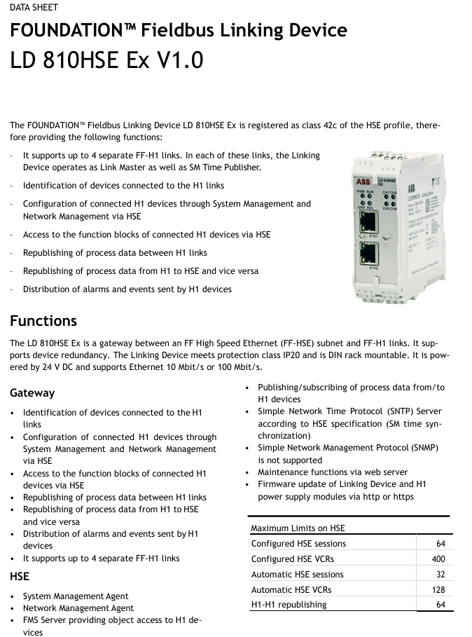
Product type: LD 810HSE Ex is a foundation launched by ABB ™ The Fieldbus (Foundation Fieldbus) connection device is registered as a 42c class device according to the HSE protocol specification. Its core function is to serve as a gateway between the FF-HSE (Foundation High Speed Ethernet) subnet and the FF-H1 link, enabling data exchange and management between different bus networks.
Physical and power characteristics: Protection level is IP20, supporting DIN rail installation; Powered by 24V DC, compatible with Ethernet transmission rates of 10 Mbit/s or 100 Mbit/s, and supports device redundancy configuration to enhance operational reliability in industrial scenarios.
Core functions
(1) Gateway core capability
LD 810HSE Ex serves as a gateway, responsible for key data exchange and device management between the FF-HSE subnet and the FF-H1 link. Its specific functions are as follows:
H1 Device Management: Automatically identify all devices connected to the H1 link and configure these H1 devices through the HSE network using System Management and Network Management functions; Simultaneously supporting the access of H1 device function blocks through HSE, enabling remote control and parameter reading of on-site devices.
Data forwarding and synchronization: supports process data forwarding between H1 links, as well as bidirectional process data forwarding between H1 and HSE subnets, ensuring real-time data interoperability at different network levels; As an SM Time Publisher, it distributes system time to H1 devices and provides a unified time reference for alarm timestamps.
Alarm and Event Distribution: Collect alarm and event information sent by H1 devices and distribute it to relevant devices (such as connectivity servers) in the HSE subnet, integrating it into the overall system's alarm management system.
(2) HSE side functional module
Management Agent: Integrate System Management Agent and Network Management Agent to achieve standardized management of HSE subnets and associated H1 links.
Data exchange: Built in FMS server (Fieldbus Message Specification Server) provides object access services for H1 devices; Support the publishing/subscribing mechanism for H1 device process data to meet the real-time data transmission needs in industrial scenarios.
Time synchronization and maintenance: As an SNTP server (Simple Network Time Protocol Server) that complies with HSE standards, it achieves time synchronization within the HSE network; Provide maintenance functionality through a built-in web server, supporting firmware updates for linked devices and H1 power modules via HTTP or HTTPS protocols.
Function limitation: does not support Simple Network Management Protocol (SNMP); There is a clear resource limit on the HSE side, with specific parameters as shown in the table below:
HSE resource type upper limit value
64 HSE sessions have been configured
400 HSE virtual communication relationships (VCRs) have been configured
Automatic HSE session count 32
128 automatic HSE virtual communication relationships (VCRs)
H1-H1 data forwarding count 64
(3) H1 Link Side Function Module
Management and Data Interaction: Integrate System Management Manager and Network Management Manager to lead the management logic of H1 link; As an FMS client, it implements object access while supporting the publication and subscription of process data, as well as the reception and reporting of alarms and events.
Link Control: Serve as the Link Master in each H1 link, responsible for communication scheduling and resource allocation of the link; Support access to the Management Information Base (MIB) of H1 port from H1 network, but restrict write operations from H1 network to ensure network security.
Resource limit (single H1 channel): There are clear restrictions on the resource configuration of each H1 channel, with specific parameters as shown in the table below (note: the total number of VCRs of source/sink, client/server, and publisher/subscriber types in a single H1 channel must not exceed the "total connections" limit):
H1 channel resource type upper limit value
Total number of connections (VCRs) * 128
Number of overnight connections (alarm reception) 10
Number of client server connections: 39+1
Publisher+subscriber connections 100
LAS scheduling table quantity 2
Number of sub scheduling tables 4
The number of sequences in each sub schedule table is 64
The number of elements in each sequence is 4
LAS scheduling table field size (bytes) 2000
(4) H1 Live List
Record key information of all active H1 devices on the H1 chain, including node addresses, PD tags (Process Data Tags), and device IDs, to provide basic data support for device management and troubleshooting.
(5) Built in web server
Support access through a standard web browser (with JavaScript enabled) to query general information of linked devices (such as device status, configuration parameters, etc.), provided that the PC where the browser is located is connected to LD 810HSE Ex via Ethernet.
Installation and certification in hazardous environments
(1) Applicable environmental model
LD 810HSE Ex is suitable for scenarios with potential explosive environments and complies with the hazardous location classification requirements of the North American "Division model" and the European and IEC national "Zone model".
(2) North American Certification (cULus)
Scope of application: If the equipment label has clear identification, it can be used in Class 1, Division 2, A/B/C/D hazardous or non hazardous locations.
Installation requirements: The equipment itself does not meet the requirements of impact resistance and IP54 (according to IEC 60529), and must be installed in a protective enclosure that complies with section 26.4 of IEC/EN 60079-0 (must meet the requirements of impact resistance and IP rating); The casing must be fully installed and undamaged. If the casing is damaged, the equipment is prohibited from operating.
(3) European and international certifications (ATEX, IECEx)
Certification criteria:
IEC 60079-0:2011 6th edition (including 2012 and 2013 revisions)/EN 60079-0:2012 (including A11:2013 revisions)
IEC 60079-11:2011 6th edition (including 2012 revision)/EN 60079-11:2012
IEC 60079-15:2010 4th edition/EN 60079-15:2010
Scope of application: If the equipment label or technical documentation clearly identifies it, it can be used in Zone 2 gas explosive environments with IIA, IIB, IIC explosive groups, T4 temperature levels after being installed in a tested protective enclosure.
Explosion proof label:
IECEx explosion-proof label: Ex nA [ic] IIC T4 Gc
ATEX explosion-proof label: II3G nA [ic] IIC T4 Gc
Note: [ic] Explosion proof method is only applicable to the FF-H1 fieldbus interface.
Compliance requirements: The equipment complies with relevant standards and regulations, and meets the requirements of Directive 2014/34/EU; When installed as part of a system in potentially explosive environments, it is necessary to strictly comply with the requirements of standards such as IEC/EN 60079-14.
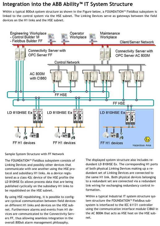
At ABB Ability ™ Integration in IT system (800xA system)
(1) System Architecture Role
In a typical 800xA system architecture, FOUNDATION ™ The Fieldbus subsystem is connected to the control system (such as the AC 800M controller) through the HSE subnet, with LD 810HSE Ex serving as the gateway to establish a communication bridge between the field devices on the H1 link and the HSE subnet. The specific architecture is as follows:
Upper level system: including engineering workstation (Control Builder M workstation), operator maintenance workstation, Fieldbus Builder FF client/server network, and connectivity server with OPC server (FF Connectivity Server).
Control layer: The AC 800M controller is connected to the HSE subnet through the communication interface module CI860 (as the HSE host) to achieve control and data exchange of the Fieldbus subsystem.
Fieldbus subsystem: composed of multiple LD 810HSE Ex linked devices and H1 field devices, the linked devices communicate through HSE protocol and manage the H1 links under them, realizing the forwarding of process data and device management.
(2) Key integration capabilities
Data exchange: With the help of HSE data forwarding function, periodic communication between different H1 link on-site devices and HSE subnet devices can be configured to meet real-time control requirements.
Alarm integration: The alarms and events of H1 devices are transmitted to the FF connectivity server through linked devices, seamlessly integrated into the alarm management system of the 800xA system for unified monitoring and processing.
Redundant configuration: Supports LD 810HSE Ex redundant deployment, where the corresponding H1 ports of two physically linked devices in the redundant group are connected to the same H1 link, and redundant control information is exchanged through redundant link wiring to enhance system reliability.
Technical specifications and parameters
Technical parameter category specific parameters
Power supply input voltage: 18 V DC~32 V DC (mandatory requirement for SELV/PELV power supply); Typical input current: 200 mA; 4 FF-H1 channels output current: 10 mA each; maximum input current: 1 A (including startup surge current)
FF-H1 channel quantity: 4; Compliant with FF physical layer protocol specification Class 114; Fieldbus voltage range: 9 V DC~32 V DC (recommended value 24 V DC)
Ethernet complies with the IEEE 802.3 standard; Supports 100BASE-TX (100 Mbit/s) and 10BASE-T (10 Mbit/s)
Environmental temperature: Operating temperature: -40 ° C~+70 ° C; Storage temperature: -40 ° C~+85 ° C
Relative humidity 10%~95% (non condensing)
The highest altitude shall not exceed 2000 meters
Installation location for indoor use only; Avoid direct sunlight
The coating complies with the ANSI/ISA-S71.04 G3 standard and is a three proof coating (moisture-proof, salt spray resistant, and mold resistant)
The safety standards comply with IEC/EN/UL 61010-1 (Safety Requirements for Electrical Equipment for Measurement, Control and Laboratory Use - Part 1: General Requirements) and IEC/EN/UL 61010-2-201 (Part 2-201: Special Requirements for Control Equipment), both of which have passed the CB certification system
Protection level IP20
- OMRON
- ABB
- General Electric
- EMERSON
- Honeywell
- HIMA
- ALSTOM
- Rolls-Royce
- MOTOROLA
- Rockwell
- Siemens
- Woodward
- YOKOGAWA
- FOXBORO
- KOLLMORGEN
- MOOG
- KB
- YAMAHA
- BENDER
- TEKTRONIX
- Westinghouse
- AMAT
- AB
- XYCOM
- Yaskawa
- B&R
- Schneider
- KONGSBERG
- NI
- WATLOW
- ProSoft
- SEW
- ADVANCED
- Reliance
- TRICONEX
- METSO
- MAN
- Advantest
- STUDER
- DANAHER MOTION
- Bently
- Galil
- EATON
- MOLEX
- DEIF
- B&W
- ZYGO
- Aerotech
- DANFOSS
- Beijer
- Moxa
- Rexroth
- Johnson
- WAGO
- TOSHIBA
- BMCM
- SMC
- HITACHI
- HIRSCHMANN
- Application field
- XP POWER
- CTI
- TRICON
- STOBER
- Thinklogical
- Horner Automation
- Meggitt
- Fanuc
- Baldor
- SHINKAWA
- Other Brands
- UniOP
- KUKA
- Iba
- Beckhoff
-
 Basler DECS-200-2L Digital Excitation Control
 -
 Basler BE1-47N Voltage Phase Sequence Relay
 -
 Basler AEC63-7 Analog Excitation Controller 220-277V
 -
 Basler BE1-50/51B-107 Overcurrent Relay
 -
 Basler Electric BE1‑32R BE1‑E1P‑BON0F Protective Relay
 -
 Basler BE1-25 Solid State Time Overcurrent Relay M1EA6PA5S1F
 -
 Basler MVC 232 Manual Voltage Control Module 90 37000 103 60VAC 55VDC
 -
 Basler RAL6144-16GM Racer GigE Line Scan Camera
 -
 Basler SSR 63-12 Static Voltage Regulator
 -
 Basler BE1-51A Overcurrent Relay
 -
 Basler BE1-87T Solid State Protective Relay
 -
 Basler SR4A2B01B3A Static Voltage Regulator
 -
 Basler SSR 32-12 Static Voltage Regulator
 -
 Basler TRR00696 Transformer 1KVA 115V
 -
 Basler DECS-100-B15 AVR Replacement
 -
Basler BE1-27 Under-Voltage Relay
-
 Basler ACA2000-50GM Interface Module
 -
 Basler AEC63-7 Analog Excitation Controller
 -
 Basler PRS 250 Veri-Sync Relay
 -
 Basler SR4A-2B15B3A Static Voltage Regulator
 -
Basler BE1-32R Power Relay
-
Basler SR8A-2B06B3E Static Voltage Regulator
-
Basler BE1-81 O/U Frequency Relay
-
 Basler BE1-51A-K2E-W6M-B1N0F Overcurrent Relay
 -
Basler BE1-851 Overcurrent Relay G3A1S1 – 48-125V AC/DC
-
 Basler BEI-51 Overcurrent Relay – NSN 5945-01-293-2363
 -
Basler Electric L301KC Protective Relay – L301KC
-
 Basler DECS-100-B15 Automatic Voltage Regulator – Generator AVR
 -
 Basler SR4A-2B15B3A Static Voltage Regulator – SR4A2B15B3A
 -
 Basler UF 312 Under Frequency Protective Module – 9094700100
 -
Basler Electric MVC 232 Manual Control Module – 60VAC 55VDC 20A
-
Basler PRS 250 Veri-Sync Relay – Generator Synchronizing Relay
-
 Basler DECS-100-A05 Digital Regulator Review
 -
 Basler AEM-2020 Analog Expansion Module Specs
 -
 Basler DECS-100-B15 Digital Excitation Specs
 -
Basler Electric 9125600106 Regulator Component
-
Basler BE1-51A-K1E-W6M-B1N0F Overcurrent Relay
-
 Basler MVC-301 MVC 300 Excitation Controller
 -
 Basler SSR 32-12 Static Voltage Regulator
 -
 Basler 9-2849-00-101 Control Module
 -
Basler BE1-51A Overcurrent Relay
-
 Basler BE1-51/27R Overcurrent Relay
 -
 Basler BE1-51 Overcurrent Relay
 -
 Basler SR8A-2B15B3A Static Voltage Regulator
 -
 Basler BE32965001 Transformer and Timer Board
 -
 Basler 9174700100 EL200-7 Excitation Limiter
 -
 Basler BE2000E AVR Voltage Regulator
 -
Basler BE1-87G Differential Relay
-
 Basler BE21834001 Generator Control Module
 -
Basler DECS-100-B15 AVR
-
 Basler D90 96801 100 PCB Card
 -
 Basler XR2002F Voltage Regulator (110 VAC, 48-480 Hz)
 -
 Basler SR8A-2B14B3A Regulator
 -
 Basler 9561500100 Module
 -
 Basler DECS-400 BE1-11 System
 -
 Basler DECS-100-B15 Excitation Control
 -
 Basler SCP 210 Frequency Controller
 -
Basler SR4A-2B15B3A Static Voltage Regulator
-
Basler BE1-32R Power Relay
-
 Basler PIA2400-17GM Power Interface Adapter
 -
 Basler MVC 232 Manual Voltage Control Module
 -
 Basler SSR 32-12 Static Voltage Regulator
 -
Basler 5MW AVR Generator Voltage Regulator
-
 Basler VR63-4B Voltage Regulator
 -
Basler DECS-100-A05 AVR for Engine Generator
-
Basler DECS-100-B15 Automatic Voltage Regulator
-
Basler BE1-32R Directional Power Relay
-
Basler BE1-87B Differential Relay
-
 Basler UFOV 260A Protective Module
 -
 Basler 9-2614-02-100 PCB Rev M
 -
Basler DECS-100-B15 Digital AVR
-
 Basler 9284900103 PS DECS-400N
 -
 Basler D4N3H1U Intertie Protection
 -
 Basler DECS-100-B15 A15 AVR
 -
 Basler KR4F Voltage Regulator
 -
 Basler BE26434 T14 Transformer
 -
 Basler SR8A-2B15B3A Regulator
 -
 Westinghouse 774B472A12 AR Relay
 -
Basler DECS-100-B15 AVR
-
Basler XR2002F Regulator 110V
-
Basler SR125-E Static Regulator
-
Basler SSR 125-12 Regulator
-
Basler MOC2599 Motor Pot
-
 Basler BE1-DFPR Feeder Relay
 -
 Basler CBS 305 Current Boost
 -
Basler BE1-25 AutoSync
-
Basler MVC 300 Voltage Control
-
 Basler BE3-25A AutoSync
 -
 Basler KR7FF Static Regulator
 -
Basler 90-49000-100 Regulator
-
 Basler 880 kVA Dry Type Transformer Specs
 -
Basler Electric BE1-25 Sync-Check Relay Specs
-
 Basler SSR 125-12 Voltage Regulator Specs
 -
 Basler Electric BE1-851 Overcurrent Relay Review
 -
Basler Electric 149D930G02 Control Sub-Assembly
-
 Basler Electric BE1-81O/UT Frequency Relay Specs
 -
 Basler Electric BE1-51/27C Overcurrent Relay
 -
 Basler Electric 149D956G02 Industrial Component
 -
Basler Electric BE1-51A Overcurrent Relay Specs
-
 Basler Electric BE1-40Q Loss of Excitation Relay
 -
Basler DECS-200 Excitation Control System
-
 Basler DECS-200 Voltage Regulator 56-277V AC / 125V DC
 -
Basler BE1-87T Transformer Differential Relay
-
 Basler RDP-110-S1 Protection Relay
 -
 Basler BE1-700V Digital Protective Relay
 -
 Basler BE1-951 Overcurrent Protection System
 -
 Basler DECS-300 Digital Excitation Control
 -
 Basler DECS-200 Digital Excitation Control
 -
 Basler DECS-200-1C Excitation Control System
 -
Basler DECS-200-1L Digital Excitation Control
-
 Basler Electric BE1-GPS Generator Protection System
 -
Basler Electric DECS-200-1C Digital Excitation Controller
-
 Basler Electric DECS125-15 Excitation Control with Power Module
 -
Basler Electric BE1-87G Differential Relay
-
 Basler Electric BE1-11 Protection System I5A3M2P2N0EA00
 -
Basler Electric DECS-200-1C Excitation Control System
-
Basler Electric BE1-11g Generator Protection Relay
-
Basler Electric DECS 125-15-B2C1 V2.0.9 Excitation Control
-
Basler Electric BE1-81O/UT3ED1JA7N2F Frequency Relay
-
Basler Electric BE1-81O/UT3EE1YB7N1F Frequency Relay
-
 Basler Electric DECS-200-1L Digital Excitation Control System
 -
Basler DECS125-15-B2C1 Excitation Control
-
 Basler 9507900205 SSR Retrofit Voltage Regulator
 -
 Basler BE2000E Digital Voltage Regulator
 -
 Basler BE1-GPS Generator Protection System
 -
Basler DECS-250-CN1CN1N Digital Excitation Control
-
 Basler DGC-2020 Genset Controller
 -
Basler BE1-81O UT3ED1LA7N0F Frequency Relay (Variant)


