TEKTRONIX 3 Series Mixed Domain Oscilloscope MDO32 and MDO34
TEKTRONIX 3 series mixed domain oscilloscopes MDO32 and MDO34
Overview and Scope of Application
The specification and performance verification manual for the Tektronix 3 series hybrid domain oscilloscope (with 2 channels for MDO32 and 4 channels for MDO34) covers three major modules: hardware parameters (analog bandwidth of 100MHz-1GHz, maximum sampling rate of 5GS/s, and 16 optional digital channels), multi domain functionality (oscilloscope+spectrum analyzer+arbitrary function generator+digital voltmeter), and performance verification process (20+tests including input impedance, DC balance, analog bandwidth, etc.). The key indicator range is clearly defined (such as maximum input voltage of 300VRMS, display average noise level ≤ -109dBm/Hz), and standardized testing steps are provided (including required equipment list, wiring diagram, data recording table), while emphasizing safety specifications (CAT II). Provide complete technical guidance for instrument calibration, troubleshooting, and compliance verification, including installation category and grounding requirements.
Model differences and core parameters
Model Features MDO32 (2 channels) MDO34 (4 channels) Remarks
Analog bandwidth 100MHz-1GHz 100MHz-1GHz model sampling rate 5GS/s, other 2.5GS/s
Digital channel 16 channels (3-MSO option) 16 channels (3-MSO option) input capacitor 8pF, minimum signal swing 500mVpp
Spectrum analysis 9kHz-1GHz (standard)/3GHz (3-SA3 option) 9kHz-1GHz (standard)/3GHz (3-SA3 option) Display average noise level ≤ -109dBm/Hz
AFG function 1 channel (3-AFG option) 1 channel (3-AFG option) Output waveform includes 13 types such as sine wave, square wave, pulse, etc
Size and weight 370 × 252 × 148.6mm, 5.26kg (1GHz) 370 × 252 × 148.6mm, 5.31kg (1GHz) requires 50.8mm heat dissipation space on the right and rear
Detailed explanation of core hardware specifications
1. Key parameters of simulation channel
Parameter Category Specification Range Remarks
Under the bandwidth of 100MHz/200MHz/350MHz/500MHz/1GHz 1mV/div, the bandwidth of the 1GHz model has been reduced to 150MHz
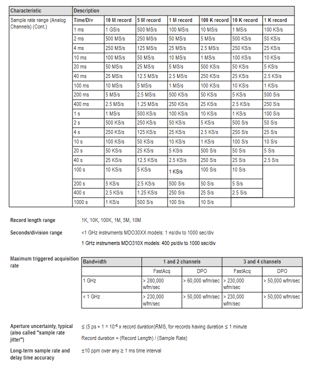
Sampling rate of 1-5GS/s, maximum 5GS/s when 1-2 channels are activated, and maximum 2.5GS/s when 3-4 channels are activated
Input impedance 1M Ω (± 1%) or 50 Ω (± 1%) 1M Ω input capacitor 13pF ± 2pF
Maximum input voltage 1M Ω: 300VRMS (CAT II); 50 Ω: 5VRMS (peak ≤± 20V) 1M Ω drops to 5VRMS above 450MHz
DC gain accuracy ± 1.5% (5mV/div and above), ± 2.0% (2mV/div), ± 2.5% (1mV/div), with an additional decrease of 0.1% per ℃ above 30 ℃
2. Digital channel (3-MSO option) parameters
Parameter specifications
Number of channels 16 (D0-D15)
Input resistance 101k Ω (typical value)
Input capacitance 8pF (typical value)
Threshold range -15V~+25V
Threshold accuracy ± [130mV+3% x threshold setting] (SPC needs to be performed)
Minimum detectable pulse 2.0ns (requires P6316 probe)
Skew 500ps between channels (typical value)
3. Parameters of spectrum analyzer
Parameter specifications
Frequency range 9kHz-1GHz (standard); 9kHz-3GHz (3-SA3 option)
Resolution bandwidth (RBW) 20Hz-150MHz (1-2-3-5 sequence adjustment)
Display average noise level (DANL) 9kHz-50kHz: ≤ -109dBm/Hz; 5MHz-2GHz:≤-136dBm/Hz
Stray response second harmonic ≤ -55dBc; 3rd harmonic ≤ -53dBc
Phase noise (1GHz CW) 10kHz offset: ≤ -81dBc/Hz; 1MHz offset: ≤ -118dBc/Hz
4. Parameters of any function generator (3-AFG option)
Parameter specifications
13 types of output waveforms including sine wave, square wave, pulse, and ramp
Frequency range: sine wave 0.1Hz-50MHz; Square wave 0.1Hz-25MHz
Range of amplitude 50 Ω load: 10mVpp-2.5Vpp; High resistance load: 20mVpp-5Vpp
DC offset ± 1.25V (50 Ω); ± 2.5V (high resistance)
Rise/fall time 5ns (10% -90%, square wave)
Distortion sine wave ≤ 1% (50 Ω, 1kHz)

Performance verification process
1. Verify the prerequisites
The instrument needs to be preheated in an environment of 18 ℃ -28 ℃ for at least 10 minutes;
Perform signal path compensation (SPC) (path: Utility → Calibration → Run SPC), if the temperature change exceeds 5 ℃, it needs to be re executed;
The oscilloscope and testing equipment need to be connected to the same AC power circuit (to avoid errors caused by ground offset).
2. Core test items and steps (example)
Qualification criteria for key steps of testing equipment in testing projects
Input impedance (1M Ω/50 Ω) DC voltage source, impedance measuring instrument 1. Connect the voltage source to channel 1; 2. Set the vertical gear to 10mV/div/100mV/div; 3. Measure impedance values of 1M Ω: 990k Ω -1.01M Ω; 50 Ω: 49.5 Ω -50.5 Ω
DC balanced 50 Ω terminal load 1. Channel connected to 50 Ω terminal; 2. Set the vertical gear to 1mV/div-1V/div; 3. Convert the measurement mean to divisions 1mV/div (50 Ω): ± 0.5div; 2mV/div and above: ± 0.2div
Analog bandwidth sine wave generator 1. Input 10MHz signal (8div amplitude); 2. Adjust to the maximum bandwidth frequency; 3. Calculate the gain (Vbw pp/Vin pp) with a gain ≥ 0.707 (-3dB point)
Random noise free (internal noise) 1. Disconnect all inputs; 2. Set up a 50 Ω terminal with full bandwidth; 3. Measure AC RMS noise at 100mV/div level: 1GHz model ≤ 3.1mV; 100MHz model ≤ 2.85mV
Digital threshold accuracy DC voltage source, P6316 probe 1. Connect the probe to the voltage source; 2. Set a threshold of 0V/4V; 3. Record Vs - (high → low) and Vs+(low → high) 0V: ± 0.1V; 4V: 3.78V-4.22V
- ABB
- General Electric
- EMERSON
- Honeywell
- HIMA
- ALSTOM
- Rolls-Royce
- MOTOROLA
- Rockwell
- Siemens
- Woodward
- YOKOGAWA
- FOXBORO
- KOLLMORGEN
- MOOG
- KB
- YAMAHA
- BENDER
- TEKTRONIX
- Westinghouse
- AMAT
- AB
- XYCOM
- Yaskawa
- B&R
- Schneider
- Kongsberg
- NI
- WATLOW
- ProSoft
- SEW
- ADVANCED
- Reliance
- TRICONEX
- METSO
- MAN
- Advantest
- STUDER
- KONGSBERG
- DANAHER MOTION
- Bently
- Galil
- EATON
- MOLEX
- Triconex
- DEIF
- B&W
- ZYGO
- Aerotech
- DANFOSS
- Beijer
- Moxa
- Rexroth
- Johnson
- WAGO
- TOSHIBA
- BMCM
- SMC
- HITACHI
- HIRSCHMANN
- Application field
- XP POWER
- CTI
- TRICON
- STOBER
- Thinklogical
- Horner Automation
- Meggitt
- Fanuc
- Baldor


