
TEKTRONIX 3 Series Mixed Domain Oscilloscope MDO32 and MDO34
TEKTRONIX 3 series mixed domain oscilloscopes MDO32 and MDO34
Overview and Scope of Application
The specification and performance verification manual for the Tektronix 3 series hybrid domain oscilloscope (with 2 channels for MDO32 and 4 channels for MDO34) covers three major modules: hardware parameters (analog bandwidth of 100MHz-1GHz, maximum sampling rate of 5GS/s, and 16 optional digital channels), multi domain functionality (oscilloscope+spectrum analyzer+arbitrary function generator+digital voltmeter), and performance verification process (20+tests including input impedance, DC balance, analog bandwidth, etc.). The key indicator range is clearly defined (such as maximum input voltage of 300VRMS, display average noise level ≤ -109dBm/Hz), and standardized testing steps are provided (including required equipment list, wiring diagram, data recording table), while emphasizing safety specifications (CAT II). Provide complete technical guidance for instrument calibration, troubleshooting, and compliance verification, including installation category and grounding requirements.
Model differences and core parameters
Model Features MDO32 (2 channels) MDO34 (4 channels) Remarks
Analog bandwidth 100MHz-1GHz 100MHz-1GHz model sampling rate 5GS/s, other 2.5GS/s
Digital channel 16 channels (3-MSO option) 16 channels (3-MSO option) input capacitor 8pF, minimum signal swing 500mVpp
Spectrum analysis 9kHz-1GHz (standard)/3GHz (3-SA3 option) 9kHz-1GHz (standard)/3GHz (3-SA3 option) Display average noise level ≤ -109dBm/Hz
AFG function 1 channel (3-AFG option) 1 channel (3-AFG option) Output waveform includes 13 types such as sine wave, square wave, pulse, etc
Size and weight 370 × 252 × 148.6mm, 5.26kg (1GHz) 370 × 252 × 148.6mm, 5.31kg (1GHz) requires 50.8mm heat dissipation space on the right and rear
Detailed explanation of core hardware specifications
1. Key parameters of simulation channel
Parameter Category Specification Range Remarks
Under the bandwidth of 100MHz/200MHz/350MHz/500MHz/1GHz 1mV/div, the bandwidth of the 1GHz model has been reduced to 150MHz
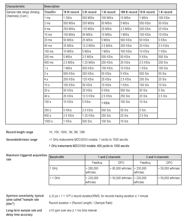
Sampling rate of 1-5GS/s, maximum 5GS/s when 1-2 channels are activated, and maximum 2.5GS/s when 3-4 channels are activated
Input impedance 1M Ω (± 1%) or 50 Ω (± 1%) 1M Ω input capacitor 13pF ± 2pF
Maximum input voltage 1M Ω: 300VRMS (CAT II); 50 Ω: 5VRMS (peak ≤± 20V) 1M Ω drops to 5VRMS above 450MHz
DC gain accuracy ± 1.5% (5mV/div and above), ± 2.0% (2mV/div), ± 2.5% (1mV/div), with an additional decrease of 0.1% per ℃ above 30 ℃
2. Digital channel (3-MSO option) parameters
Parameter specifications
Number of channels 16 (D0-D15)
Input resistance 101k Ω (typical value)
Input capacitance 8pF (typical value)
Threshold range -15V~+25V
Threshold accuracy ± [130mV+3% x threshold setting] (SPC needs to be performed)
Minimum detectable pulse 2.0ns (requires P6316 probe)
Skew 500ps between channels (typical value)
3. Parameters of spectrum analyzer
Parameter specifications
Frequency range 9kHz-1GHz (standard); 9kHz-3GHz (3-SA3 option)
Resolution bandwidth (RBW) 20Hz-150MHz (1-2-3-5 sequence adjustment)
Display average noise level (DANL) 9kHz-50kHz: ≤ -109dBm/Hz; 5MHz-2GHz:≤-136dBm/Hz
Stray response second harmonic ≤ -55dBc; 3rd harmonic ≤ -53dBc
Phase noise (1GHz CW) 10kHz offset: ≤ -81dBc/Hz; 1MHz offset: ≤ -118dBc/Hz
4. Parameters of any function generator (3-AFG option)
Parameter specifications
13 types of output waveforms including sine wave, square wave, pulse, and ramp
Frequency range: sine wave 0.1Hz-50MHz; Square wave 0.1Hz-25MHz
Range of amplitude 50 Ω load: 10mVpp-2.5Vpp; High resistance load: 20mVpp-5Vpp
DC offset ± 1.25V (50 Ω); ± 2.5V (high resistance)
Rise/fall time 5ns (10% -90%, square wave)
Distortion sine wave ≤ 1% (50 Ω, 1kHz)
Performance verification process
1. Verify the prerequisites
The instrument needs to be preheated in an environment of 18 ℃ -28 ℃ for at least 10 minutes;
Perform signal path compensation (SPC) (path: Utility → Calibration → Run SPC), if the temperature change exceeds 5 ℃, it needs to be re executed;
The oscilloscope and testing equipment need to be connected to the same AC power circuit (to avoid errors caused by ground offset).
2. Core test items and steps (example)
Qualification criteria for key steps of testing equipment in testing projects
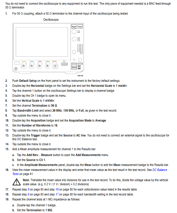
Input impedance (1M Ω/50 Ω) DC voltage source, impedance measuring instrument 1. Connect the voltage source to channel 1; 2. Set the vertical gear to 10mV/div/100mV/div; 3. Measure impedance values of 1M Ω: 990k Ω -1.01M Ω; 50 Ω: 49.5 Ω -50.5 Ω
DC balanced 50 Ω terminal load 1. Channel connected to 50 Ω terminal; 2. Set the vertical gear to 1mV/div-1V/div; 3. Convert the measurement mean to divisions 1mV/div (50 Ω): ± 0.5div; 2mV/div and above: ± 0.2div
Analog bandwidth sine wave generator 1. Input 10MHz signal (8div amplitude); 2. Adjust to the maximum bandwidth frequency; 3. Calculate the gain (Vbw pp/Vin pp) with a gain ≥ 0.707 (-3dB point)
Random noise free (internal noise) 1. Disconnect all inputs; 2. Set up a 50 Ω terminal with full bandwidth; 3. Measure AC RMS noise at 100mV/div level: 1GHz model ≤ 3.1mV; 100MHz model ≤ 2.85mV
Digital threshold accuracy DC voltage source, P6316 probe 1. Connect the probe to the voltage source; 2. Set a threshold of 0V/4V; 3. Record Vs - (high → low) and Vs+(low → high) 0V: ± 0.1V; 4V: 3.78V-4.22V
3. List of Testing Equipment (Table 3)
Minimum requirements for device name, example model
DC voltage source 3mV-100V, ± 0.1% accuracy Fluke 9500B (equipped with 9530 module)
Sine wave generator 9kHz-3GHz, ± 4% amplitude accuracy Anritsu MG3690C
Power meter+sensor -30dBm -+10dBm Rhode&Schwarz NRX (with NRP-Z98)
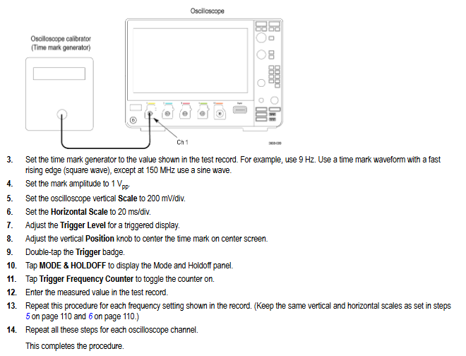
Frequency counter 0.1Hz-50MHz, 5ppm accuracy Tektronix FCA3000
Digital Multimeter (DMM) DC ± 0.1%, AC RMS ± 0.2% Tektronix DMM4040
Safety and Maintenance
1. Safety regulations
Grounding requirements: A 3-pin power cord must be used, and the grounding conductor must be reliably connected to the ground. Disconnecting the grounding is prohibited;
Input restrictions: Maximum 300VRMS (CAT II) for 1M Ω channel, maximum 5VRMS for 50 Ω channel, overvoltage may damage terminal resistance;
Operation taboos: Do not plug or unplug probes/cables with power on, do not use in damp (>90% RH) or explosive environments, and do not operate after removing the instrument cover.
2. Maintenance and Calibration
Firmware upgrade: 1 Download firmware. img from the official website to USB; 2. Turn off the oscilloscope and plug it into a USB port; 3. Automatic upgrade upon startup (power off prohibited);
Calibration cycle: recommended to be 1 year, with a reference frequency error accumulation of ± 10ppm/year (including aging and temperature effects);
Self check and diagnosis: Path: Utility → Self Test. If it fails, it will enter extended diagnosis and can be exited by pressing MENU OFF (it can be temporarily used when the fault does not affect the measurement).
Key issue
Question 1:3: The simulated bandwidth of the 3 series MDO is related to the vertical gear. What is the actual bandwidth of the 1GHz model at different vertical gears? How to confirm whether the bandwidth is qualified through performance verification?
Answer:
1、 Actual bandwidth of different vertical gears for 1GHz models
The simulated bandwidth of the 1GHz model decays with decreasing vertical gear, and the specific corresponding relationship is as follows:
Vertical gear (Volts/Div) 50 Ω input bandwidth 1M Ω input bandwidth (typical value)
10mV/div - 1V/div DC - 1.0GHz DC - 1.0GHz
5mV/div - 9.98mV/div DC - 500MHz DC - 500MHz
2mV/div - 4.98mV/div DC - 350MHz DC - 350MHz
1mV/div - 1.99mV/div DC - 150MHz DC - 150MHz
2、 Bandwidth performance verification steps (taking 50 Ω input as an example)
Equipment connection: Connect a sine wave generator (such as Fluke 9500B) to oscilloscope channel 1 via a 50 Ω coaxial cable, with the generator output impedance set to 50 Ω;
Oscilloscope settings:
Reset according to Default Setup;
Set the Acquisition Mode to Sample;
Add peak to peak measurement (Measure → Amplitude → Peak to Peak → Add);
Channel 1 setting: Termination=50 Ω, Vertical Scale=corresponding test gear (such as 1mV/div);
Signal input: The generator outputs a 10MHz sine wave, adjust the amplitude to display 8div on the screen (such as outputting 8mVpp at 1mV/div level), and record the peak value (Vin pp) at this time;
Bandwidth test: Adjust the generator frequency to the maximum bandwidth corresponding to this gear (e.g. 1mV/div corresponds to 150MHz), and record the peak value (Vbw pp) at this time;
Qualification judgment: Calculate the gain as Vbw-pp/Vin pp. If the gain is ≥ 0.707 (-3dB point), the bandwidth is qualified.
Question 2: How to test the threshold accuracy of the digital channel (3-MSO option) of the 3 series MDO? What are the key operational details to pay attention to during testing?
Answer:
1、 Testing steps for threshold accuracy of digital channels
Equipment preparation: DC voltage source (such as Fluke 9500B), P6316 digital probe, BNC-to-0.1 inch pin adapter;
Probe connection: P6316 probe Group 1 is connected to a voltage source, and an adapter is used to match the interface;
Oscilloscope settings:
Reset according to Default Setup;
Activate the digital channel (D15-D0 button → Turn All On);
Set digital channel threshold (such as 0V or 4V): D15-D0 menu → Thresholds → Enter target value;
Trigger setting: Trigger → Source=Target digital channel (such as D0), Slope=Rising/Falling;
Threshold measurement (taking 0V threshold as an example):
Vs - (high to low switching voltage): Set the voltage source to -400mV, gradually increase by 20mV until the channel displays a stable low level (blue), and record the voltage as Vs - at this time;
Vs+(low to high switching voltage): Set the voltage source to+400mV, gradually -20mV until the channel displays a stable high level (green), and record the voltage as Vs+at this time;
Calculate the average threshold: VSAvg=(Vs -+Vs+)/2;
Qualification judgment: The 0V threshold must meet the requirement of * * -0.1V ≤ VSAvg ≤ 0.1V * *, and the 4V threshold must meet the requirement of 3.78V ≤ VSAvg ≤ 4.22V.
2、 Key operational details
Probe grounding: All 8 grounding channels of P6316 probe need to be connected to user grounding to avoid threshold deviation caused by poor grounding;
Voltage stepping: After adjusting the voltage each time, wait for 3 seconds to ensure that the channel state is stable before recording to avoid transient interference;
Trigger slope switching: When measuring Vs -, use the Rising slope, and when measuring Vs+, use the Falling slope to ensure that the trigger point is consistent with the level switching;
Multi channel testing: After testing each channel (such as D0), set its Display to Off and activate the next channel (such as D1) to avoid interference between channels.
Question 3: How to test the display average noise level (DANL) in the spectrum analyzer function of the 3 series MDO? What are the DANL qualification standards for different frequency ranges?
Answer:
1、 DANL testing steps (no input signal, only 50 Ω terminal required)
Equipment connection: oscilloscope RF input connected to 50 Ω feedthrough terminal, no external signal input;
Oscilloscope settings:
Reset according to Default Setup;
Activate RF channel (RF button → On);
Set Trace mode: RF menu → Traces → Average=On, Normal=Off;
Detection mode: Detection Method → Manual → Average;
Reference level: Vertical Settings → Ref Level=-15dBm;
Frequency range setting and measurement:
9kHz-50kHz: Orizontal → Start=9kHz, Stop=50kHz, move the Marker (Multipurpose knob a) to the highest noise point, and record the DANL value;
50kHz-5MHz:Start=50kHz,Stop=5MHz,Center=2.525MHz, Record the highest noise level;
5MHz-2GHz (3-SA3 option): Start=5MHz, Stop=2GHz, Center=1GHz, Span=10MHz, record the highest noise value;
2GHz-3GHz (3-SA3 option): Start=2GHz, Stop=3GHz, Center=2.5GHz, Span=10MHz, record the highest noise value;
Data processing: Ignore stray signals above the noise level (refer to the "residual response" specification) and only record the noise baseline value.
2、 DANL qualification standards for different frequency ranges
Frequency range standard (without 3-SA3) 3-SA3 option typical values (better than standard)
9kHz-50kHz ≤-109dBm/Hz ≤-109dBm/Hz ≤-113dBm/Hz
50kHz-5MHz ≤-126dBm/Hz ≤-126dBm/Hz ≤-130dBm/Hz
5MHz-1GHz ≤-136dBm/Hz ≤-136dBm/Hz ≤-140dBm/Hz
1GHz-2GHz - ≤-136dBm/Hz ≤-140dBm/Hz
2GHz-3GHz - ≤-126dBm/Hz ≤-130dBm/Hz
3、 Testing precautions
Terminal matching: A 50 Ω terminal must be used, otherwise impedance mismatch may cause high noise measurement;
Stray elimination: If there is significantly higher than the base noise at a certain frequency point (such as 1.25GHz, 2.5GHz), the noise values on both sides of the noise should be recorded, rather than the noise itself;
Average time: In the low-frequency range (such as 9kHz-50kHz), wait for 60 seconds to ensure that the average trace is stable before reading.
- OMRON
- ABB
- General Electric
- EMERSON
- Honeywell
- HIMA
- ALSTOM
- Rolls-Royce
- MOTOROLA
- Rockwell
- Siemens
- Woodward
- YOKOGAWA
- FOXBORO
- KOLLMORGEN
- MOOG
- KB
- YAMAHA
- BENDER
- TEKTRONIX
- Westinghouse
- AMAT
- AB
- XYCOM
- Yaskawa
- B&R
- Schneider
- KONGSBERG
- NI
- WATLOW
- ProSoft
- SEW
- ADVANCED
- Reliance
- TRICONEX
- METSO
- MAN
- Advantest
- STUDER
- DANAHER MOTION
- Bently
- Galil
- EATON
- MOLEX
- DEIF
- B&W
- ZYGO
- Aerotech
- DANFOSS
- Beijer
- Moxa
- Rexroth
- Johnson
- WAGO
- TOSHIBA
- BMCM
- SMC
- HITACHI
- HIRSCHMANN
- Application field
- XP POWER
- CTI
- TRICON
- STOBER
- Thinklogical
- Horner Automation
- Meggitt
- Fanuc
- Baldor
- SHINKAWA
- Other Brands
- UniOP
- KUKA
- Iba
- Beckhoff
- ADLINK
-
 Beckwith M-0145 First Customer Protector
 -
 Beckwith M-0170A AC Current Relay
 -
 Beckwith PRIDE M-0296C 3 Phase Programmable Relay
 -
 Beckwith Pride M-0296b 3-Phase Programmable Relay
 -
Beckwith M-0245C High Speed Sync-Check Relay Guide
-
 Beckwith M-0115A AC Parallel Balancing Module
 -
 Beckwith M-0389 Voltage Verifier Relay
 -
Beckwith M-0115A Parallel Balancing Module
-
Beckwith M-0389 Voltage Verifier
-
 Beckwith PRIDE M-0420 Multifunction Relay Protection Module 48VDC
 -
 Beckwith Electric M-3430 Generator Protection Relay
 -
 Beckwith Electric M-0067E Tapchanger Control
 -
Beckwith Electric M-0420 Multifunction Relay
-
 Beckwith Electric M-2001D-6L4S20C0S0X Tap Changer Control
 -
 Beckwith Electric M3425A-STD1 Generator Protection Relay
 -
 Beckwith Electric M-0245C High Speed Sync-Check Relay
 -
Beckwith Electric M-3520 Intertie Protection Relay Guide
-
Beckwith Electric M-2001C-6SL Tap Changer Control
-
 Beckwith Electric M-2001C Tap Changer Control Guide
 -
Beckwith 35-12-635 Generator Protection Keypad Interface
-
 Beckwith Electric P-2216 Generator Protection Main Board
 -
 Beckwith Electric M-2293 Tap Changer Control Guide
 -
 Beckwith M-4272-6AB1EH0 Integrated Synchronizing Motor Bus Transfer
 -
Beckwith Electric M-4272 Motor Bus Transfer 60-140V 50/60Hz
-
Beckwith Electric M-2001B TapChanger Control
-
 Beckwith Electric M-0193B Synchrocloser Unit
 -
Beckwith Electric M-0115A AC Parallel Balancing Module
-
Beckwith Electric M-0169A Current Transformer
-
Beckwith Electric P-1939 Generator Protection Annunciator Panel
-
Beckwith Electric M-3311A Transformer Protection Relay Guide
-
Beckwith Electric M-0245B High Speed Sync-Check Relay
-
Beckwith Electric M3420 Generator Protection Relay
-
 Beckwith M-0193B Syncrocloser Unit
 -
 Beckwith Electric M-520 Intertie Protection Relay
 -
 Beckwith Electric M-3425A Generator Protection Relay
 -
Beckwith M-3425 Integrated Generator Protection Relay
-
Beckwith M-0115A Parallel Balancing Module
-
Beckwith Electric M-4272 Integrated Synchronizing Motor Bus Transfer
-
Beckwith Electric M-3420 Generator Protection System
-
Beckwith M-0193 Syncrocloser Unit
-
 Basler Electric DECS-250-CN1SN1N Digital Excitation Control System
 -
 Basler Electric BE1-700 E0N2X1N Digital Protective Relay
 -
 Basler Electric SR4A-2B15B3A Static Voltage Regulator 120VAC 50/60Hz
 -
 Basler Electric 9261402111 PCB Control Board 9346000033
 -
 Basler Electric BE28053-002 Transformer BE28053002
 -
 Basler Electric BE3-25A Auto Synchronizer B1D Sync Module
 -
 Basler Electric BE3-GPR Generator Protective Relay
 -
 Basler Electric SCP-250-G-60 VAR Power Factor Controller 9 1100 00 109
 -
 Basler Electric BE3-32-1S1N1 Reverse Power Relay 277V 5A
 -
 Basler Electric ACA1300-60GM Area Scan Camera 106200-17
 -
 Basler Electric UFOV 260 A Protection Module Specs
 -
 Basler Electric BE03303001 Control Module
 -
Basler Electric BE3-GPR-P1BVSF Generator Protective Relay
-
 Basler Electric BE1-87G Solid State Protective Relay Guide
 -
 BASLER ELECTRIC BE1-60 VOLTAGE BALANCE RELAY T176884
 -
 Basler Electric BE1-32R Protective Relay
 -
 Basler Electric 9022900-103 Transformer 6-7VA 60Hz
 -
 Basler Electric BE1-59-A4E-E1K-B1S3F Overvoltage Relay
 -
 Basler Electric KR2FF-M Voltage Regulator 9 1163 00 103
 -
 Basler Electric UFOV 260 A Protective Module
 -
 Basler Electric PCB Assembly 9059701100 919620
 -
 Basler Electric SR8A2B01A3E Static Voltage Regulator
 -
 Basler Electric SSR125-12 Static Voltage Regulator 9185900102
 -
 Basler Electric SSR 63-12 Static Voltage Regulator 600VAC
 -
 Basler Electric BE1-60 Solid State Protective Relay
 -
 Basler Electric BE3-47N/27-3A4N2 Voltage Relay 9320400101
 -
 Basler Electric BE1-59 Over Voltage Relay
 -
 Basler Electric DECS100-B15 Automatic Voltage Regulator
 -
 Basler Electric PRS250 Veri-Sync Relay 9088800102
 -
Basler Electric BE25927001 Current Transformer 1:34 Amp
-
Basler Electric 9170818100 Generator Differential Relay
-
 Basler Electric BE1-59N Solid State Ground Fault Overvoltage Relay
 -
 Basler Electric 1783 DC Current Transformer Coil 1200:5A
 -
Basler Electric BE1-67 Ground Directional Overcurrent Relay
-
 Basler Electric UFOV-260A Underfrequency Overvoltage Module
 -
 Basler Electric BE10493001 Control Module
 -
Basler Electric SSR125-12 Static Voltage Regulator Guide
-
 Basler Electric BE1810/U-2 Solid State Frequency Relay Guide
 -
 Basler Electric 9105100106 UFOV-250A Protector Guide
 -
 Basler Electric MOC2199 9072300-335 Relay Module Guide
 -
 Basler Electric 9289902106 Circuit Board
 -
Basler Electric BE1-32R Protective Relay A1E E1P BOS1P
-
 Basler Electric RAL6144-16GM GigE Line Scan Camera with Lens
 -
 Basler Electric BE3-49R-5I5A1 Temperature Relay
 -
 Basler Electric BE1-32R Power Relay B3E E1R A0N1F
 -
 Basler Electric SR4A2B06B3A Static Voltage Regulator Features
 -
 Basler Electric 9121000106 Manual Voltage Control MVC Guide
 -
Basler Electric SR32A-2B15B3E Static Voltage Regulator
-
 Basler Electric SR4A2B06B3A Static Voltage Regulator Guide
 -
Basler Electric 801A193F02 Hammond Transformer Module
-
 Basler Electric BE1-24 Volts Per Hertz Relay A1E F1J D1S0F
 -
 Basler Electric AEC63-7 Analog Excitation Controller 220-277V
 -
Basler Electric BE132R Power Relay T245579
-
 Basler Electric MVC 108 Manual Voltage Control 90 37000 102
 -
 Basler Electric 9022900-103 Control Transformer 6-7VA 60Hz
 -
 Basler Electric BE1-79M Plug Adapter 9170111102
 -
 Basler Electric 9 2007 00 100 Current Boost System CBS 305
 -
 Basler Electric SR4A2B01B3A Static Voltage Regulator 120V
 -
Basler Electric BE1-32R Power Solid State Relay E2E A10 A0N0F
-
Basler Electric PRS250 Veri-Sync Relay 9088800102
-
 Basler DECS 125-15-B2C Digital Excitation Control
 -
 Basler BE 13693 002 Transformer
 -
Basler BE1-59N Ground Fault Overvoltage Relay
-
 Basler BE1-79A Reclosing Relay
 -
Basler 9-1051-00-105 Overload Protection Module
-
 Basler BE1-32R Power Relay – Directional Overcurrent Guide
 -
 Basler 9319700103 BE3-27T/59T-3A1N3 Voltage Relay
 -
Basler BE1-87G Generator Differential Relay
-
 Basler BE3-25-1D1N4 9319100106 480V Relay
 -
 Basler SR8A2B07B3A Static Voltage Regulator
 -
 Basler Electric BE4-27/59 Over/Under Voltage Relay 307-2552
 -
Basler Electric SR32A2B05B3E Static Voltage Regulator
-
Basler Electric BE1-27 A3E C3J A1N6F Solid State Protective Relay
-
 Basler Electric 9174700-100 Excitation Limiter Generator
 -
Basler Electric BE1-87G Generator Differential Relay 09833
-
 Basler Electric 9310200100 Power Supply Module
 -
 Basler Electric TIEE1CD0N07 Control Module
 -
Basler Electric BE1-59N Ground Fault Relay T214750
-
Basler Electric SR8A2B10B3AX Static Voltage Regulator 9060200126
-
 Basler Electric SSR 125-12 Voltage Regulator
 -
 Rolls Royce H1111.0204 Ship Main Controller
 -
 Basler Electric BE3-32-3AC Reverse Power Relay 9 1376 00 105
 -
Basler Electric BE3-25-1A1N4 Synch Check Relay 9319100100
-
 Basler Electric SR4A-2B15B3A Static Voltage Regulator
 -
 Basler Electric SR4A-2B15B3E Static Voltage Regulator
 -
 Basler Electric 9170818100 Solid State Protective Relay
 -
 Basler Electric AEC63-7 Analog Excitation Controller
 -
Basler Electric 17483 Auxiliary Module


