
YASKAWA MEMOCON-SC 2000 series reversible counter module
YASKAWA MEMOCON-SC 2000 series reversible counter module
Core specifications of the product
1. General specifications
Category parameter details
Working environment temperature: 0~55 ℃ (storage: -20~85 ℃); Humidity: 10~90% RH (without condensation)
Environmental restrictions: no explosive, flammable, or corrosive gases; No severe vibration/impact (compliant with JIS C0911/C0912 standards)
Electrical performance and insulation strength: 1500VAC/1 minute; Insulation resistance: ≥ 100M Ω (500VDC); Anti noise: 1500V (noise simulator)
Physical dimensions: 38 (width) x 250 (height) x 104 (depth) mm (including terminal block); Weight approximately 0.6kg
Power consumption 5VDC ± 3%, 0.25A (internal consumption current)
2. Performance specifications
Detailed description of core parameters
Counter configuration with 2 independent counter circuits, supporting separate configuration function
Count digit GL20 adaptation: 6-digit decimal (0~999999); GL60S adaptation: 8-bit decimal (0~99999999)
Counting speed multiplier X1: 50kpps; X2:100kpps; X4:200kpps
Pulse input supports voltage levels of 5VDC, 12VDC, and 24VDC; Input mode: Phase A/B pulse, signed pulse
External coincidence output capability: open collector, maximum load 29V/250mA; Response time ≤ 5ms
External signals support external counting enable, external reset, and external sampling (1 counter per channel)
Test Input Common ADD Test (TST1), SUBTRACT Test (TST2) Input (Supports 12V/24V)
System configuration and installation requirements
1. System composition
Core components: Power module → CPU module → B2801 reversible counter module → Other I/O modules → Programming panel (P150) → Pulse generator
Connection relationship: The CPU module communicates with B2801 through the I/O interface, and external devices (pulse generators, sensors) are connected to B2801 through terminals, supporting multi module expansion
2. Installation specifications
(1) Environmental requirements
Prohibited installation scenarios: direct sunlight, temperatures exceeding 0-55 ℃, humidity>95% or condensation, contact with water/oil/chemicals, areas with severe vibration/impact
Installation operation: The fixing screws need to be tightened and checked regularly; Unused connector cover plates must not be removed (to prevent foreign objects from entering)
(2) Wiring requirements
Power specification: Use a power supply that meets the rated specifications to avoid overload and fire hazards
Anti interference measures:
The signal line adopts shielded twisted pair cable, and the shielding layer is grounded at a single point
The distance between the I/O line and the power line is ≥ 30cm, and bundling or wiring in the same pipe is prohibited
Install insulation transformer and noise filter on external power supply
Wiring taboos: Avoid foreign objects such as wire shavings from entering the module or installation base
(3) Switch settings
SW1: Counting bit switching (OFF=6-digit mode/GL20; ON=8-bit mode/GL60S)
SW2: Reserved unused (factory default OFF)
Four core counter functions
B2801 supports four independent counter functions, which can be configured with two separate counters through initial settings. The counting operation is not affected by the running status of the CPU (counting can still continue when the CPU stops).
1. Comparison Counter
(1) Core functions
Basic ability: addition and subtraction bidirectional counting (supports carry/borrow), outputs coincidence signals by comparing the current count value with the preset value
Coincidence mode: 3 options (current value>preset value, current value=preset value, current value<preset value)
Signal characteristics: Coincidentally, the ON/OFF state of the output is controlled by the "output disable" signal (no output when disabled in>/<mode; reset ON state when disabled in mode)
(2) Key operations
Reset logic: When powered on, the module is reset, or switched to the comparison counter mode, the current value is reset to zero from the preset value
Notes:
When the preset value is set to the maximum value (such as 999999), the>mode does not meet the coincidence condition
When the preset value is set to 0, the<mode does not meet the coincidence condition
Coincidentally, the ON/OFF time of the signal needs to be longer than the CPU scanning time to avoid unrecognized states
(3) Ladder diagram configuration
Initial settings: Configure pulse input mode, counting multiplier, and coincidence output mode through output registers 4001-4004
Example parameters: Coincidence preset value=500, pulse input mode=phase A/B, counting multiplier=X1
2. Cyclic Counter
(1) Core functions
Basic ability: Automatically reset when the current count value reaches the preset value or counting width, repeat counting in a loop
Default configuration: After initial setting, the preset value and count width are automatically set to 100
Coincidentally output: When the target value is reached, an ON signal is output, which needs to be reset through the "output disable" signal
(2) Key operations
Count width: When set to 0, the counter stays at 0 and does not perform addition or subtraction counting
Time requirement: The preset value and counting width must meet the requirement of t>5ms (to avoid signal conflicts)
Reset logic: When the external reset or current value reset signal is ON, the count stops and clears to zero
(3) Ladder diagram configuration
Core parameters: Coincidence preset value=1000, count width=2000 (maximum value 999999 in GL20 6-digit mode)
Counting process: ADD count up to 1000 → Coincidence output ON → Continue counting up to 2000 → Auto reset → Repeat loop
3. Sampling Counter
(1) Core functions
Basic ability: When receiving external sampling signals, latch the current count value and store it in the designated input register
Storage allocation: Counter 1 data is stored in input registers 1-2; Counter 2 data is stored in input registers 3-4
Sampling control: The sampling frequency can be reset through the "output disable" signal
(2) Key parameters
Sampling period: T ≥ 10ms, and must meet T ≤ (2 ¹⁹ -1)/(f · k) (GL20) or T ≤ (2 Ω³ -1)/(f · k) (GL60S), where f is the input pulse frequency and k is the magnification ratio
Signal requirements: Sampling signal ON response time<1ms, OFF response time<2ms, pulse width ≥ 5ms
(3) Operational logic
Initial state: When switching to sampling counter mode, the current value and carry/borrow flag are reset to zero
Data update: When the current value is preset, the sampled value is synchronously updated to the preset value
4. Memory Counter
(1) Core functions
Basic ability: When triggered by external sampling signals, latch the current count value and store it in the built-in data memory in the order of reception (up to 999 sets of data can be stored)
Data reading: By specifying the address through the "pointer command", the corresponding stored data can be read from the input register
Coincidence output: When the amount of stored data reaches the preset value, output a coincidence ON signal
(2) Key parameters
Storage limit: Stop sampling after the storage capacity reaches 999; When the preset value is 0, no coincidence signal is output
Sampling period: As required by the sampling counter (T ≥ 10ms, meeting frequency related constraints)
Read latency: After the local I/O pointer command is turned on, the data read latency is ≤ 3 scan cycles; Remote I/O ≤ 5 scanning cycles
(3) Operational logic
Reset control: When the "output disable" signal is turned on, the stored data is reset to zero, the storage count is reset, and the coincidence output is turned off
Pointer feature: When the pointer command is OFF, the input register displays the current count value; Display data stored at the specified address when turned on
Internal interface and signal definition
1. I/O allocation (interaction between CPU and B2801)
Interface type allocation specification signal flow direction
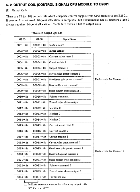
Output coil 24 points (dual counter)/16 points (single counter) CPU → B2801 (control signal)
Input relay 16 points (dual counter)/8 points (single counter) B2801 → CPU (status signal)
4 output registers (binary allocation) CPU → B2801 (set data)
4 input registers (binary allocation) B2801 → CPU (monitoring data)
2. Core control signal (output coil)
Signal Name Function Description Effective Methods
Module reset initializes internal RAM and external I/O signals, and the counter returns to its default value, triggering OFF → ON
Initial setting: Configure the counter function mode (compare/cycle/sample/store) OFF → ON trigger (count enable needs to be OFF)
Count enable, in conjunction with an external enable signal (ENB), allows the counter to count ON effectively
Output disable: Disable coincidence output or reset coincidence signal ON to be effective
The preset command (Current/Consensus/Count width preset) sets the current value, coincidence point, and count width OFF → ON trigger
Pointer command stores counter data, reads address specified ON is valid
3. Status feedback signal (input relay)
Signal Name Function Description Status Definition
READY module self diagnosis result (ROM/RAM/WDT check) ON=normal; OFF=abnormal
Preset ACK/NAK preset operation completion status feedback ACK=successful; NAK=Failed
Carry/Borrow count overflow feedback ON=1 scan cycle (compare/loop mode); Storage data overflow (sampling/storage mode)
Coincidence output - Coincidence signal output status feedback ON=coincidence condition satisfied
Scanning time error: CPU scanning time too short ON=error; OFF=Normal
4. Definition of Register Data
(1) Output register (set data)
1-2: Counter 1 dedicated (pulse mode, counting multiplier, coincidence mode, function selection, preset value, etc.)
3-4: Counter 2 dedicated (same as counter 1 configuration item)
Data range: GL20 (3-digit decimal); GL60S (4-digit decimal)
(2) Input register (monitoring data)
1-2: Counter 1 monitoring (current value, sampled value, stored data, etc.)
3-4: Monitoring of counter 2 (same as monitoring item of counter 1)
Monitoring mode: Switch through the combination of "Monitor 0~2" (e.g. 0-0-0=current value; 0-1-1=sampling times)
External interface and terminal connection
1. Front panel layout
LED indicator lights: RDY (self diagnostic status), 1ENB/2ENB (counting enabled), 1PHA/2PHA (phase A input), 1PHB/2PHB (phase B input), 1INC/2INC (addition counting), 1DEC/2DEC (subtraction counting), 1EQU/2EQU (coincidence output), 1ERR/2ERR (error alarm)
Connection terminal: 38P M3 terminal block (1/2 dedicated terminal for sub counter+common terminal)
Power terminal: 12/24V power input (providing power for external signals)
2. Key terminal functions
Terminal Type Function Description Electrical Specifications
The phase A/B (PHA/PHB) pulse input terminal supports 5V/12V/24V; Maximum input pulse 200kpps (X4 mode)
External enable (ENB) counting allows control input operating voltage of 10.2~26.4V; operating current of 4~11mA
The reset input of the RST counter and the "current value reset" signal form OR logic; Response time ≤ 6ms
External sampling (SMPL) sampling/storage trigger input pulse width ≥ 5ms; operating voltage 4.5~5.5V (5V mode)
Coincidence output (EQU): Coincidence signal output with open collector; Maximum load of 29V/250mA; ON voltage ≤ 1.5V
Test input (TST1/TST2) addition/subtraction test input operating voltage 10.2~26.4V; response time ≤ 120ms
3. Terminal connection example
Pulse generator (open collector output 12V): PHA/B terminal → pulse generator output; COM terminal → generator ground; Single point grounding of shielding layer
External enable/reset (12/24V): ENB/RST terminal → external control signal; COM terminal → power ground; Need to connect current limiting resistors in series
Coincidentally output (inductive load): EQU terminal → load positive pole; Load negative pole → power supply ground; Parallel surge absorber
4. Wiring precautions
Cable selection: Shielded twisted pair cable is used for signal lines, with a length of ≤ 30m (when 50kpps)
Grounding requirements: single point grounding of shielding layer; Connection between module FG terminal and equipment grounding system
Power isolation: External power supply is equipped with a line filter, and the primary/secondary of the filter is wired differently from the DC output terminal
Operation process and test run
1. Basic operating procedures
Installation wiring: Confirm the installation environment, fix modules, and connect terminals (shielding layer grounding, wire spacing compliance)
Switch setting: Set the number of counting bits (SW1) according to the CPU model
Initial configuration: Set counter function, pulse mode, magnification and other parameters through CPU output registers
Start counting: Activate the "count enable" signal (output coil+external ENB signal), and the counter starts working
Monitoring status: Read counting status, coincidence output, and error messages through LED indicator lights or input registers
2. Test running steps
(1) Check before powering on
Switch setting: Confirm that SW1 (counting digits) matches the CPU
Voltage matching: The input terminal voltage level is consistent with the external device
Wiring correctness: The terminal connections are not loose, there are no short circuits, and the signal polarity is correct
(2) Power on verification
Power on: After the module self diagnosis is completed, the RDY indicator light is turned on (self diagnosis time is about 0.8 seconds)
Pulse test: Operate the pulse generator, the PHA/PHB indicator light flashes (phase A/B input)
Counting direction: INC light on when ADD counts, DEC light on when SUBTRACT counts
Coincidence verification: When the preset value is reached, the EQU indicator light is turned on; reset after triggering "output disabled"
3. Initial setup steps
Configure output registers: set pulse input mode (phase A/B or signed), counting multiplier (X1/X2/X4), counter function (0=compare/1=loop/2=sample/3=store)
Activate initial settings: Output coil "Initial setting" from OFF to ON (make sure the counting enable is OFF)
Preset parameter: Set the target value through the "Coincidence/Count width preset" command
Start counting: Activate the "Count enable" coil and, in conjunction with an external ENB signal, the counter begins to run
Fault handling and diagnosis
1. Self diagnostic function
Power on diagnosis: ROM checksum check, RAM check, WDT (watchdog) check
Run diagnostics: Set up error monitoring, CPU scan time monitoring, CPU run/stop status check
Error feedback: Fault feedback through READY input relay, ERR indicator light, scan time error relay
2. Common faults and solutions
Possible causes and solutions for the fault phenomenon
RDY light OFF (module unresponsive) ROM/RAM/WDT error, power failure module reset or power failure restart; If the fault persists, replace B2801
Do not count (PHA/PHB light does not flash) pulse input wiring error, voltage level mismatch check external wiring, pulse generator output; Confirm terminal voltage
Do not count (PHA/PHB light flashing), count enable not activated, external ENB signal OFF check the status of the "Count enable" coil; Connect external enable signal
Counting error (numerical deviation), incorrect setting of counting multiplier, abnormal pulse waveform, check the counting multiplier in the initial setting; Check the output waveform of the pulse generator
Coincidentally, the preset value for abnormal output is set incorrectly, and the output disable signal is turned on to reset the coincidence point/count width; Confirm that the 'Output disable' coil is OFF
Scanning time error (1016 relay ON): CPU scanning time is too short. Add ladder program or virtual allocation; Extend scanning cycle
3. Troubleshooting process
Observe indicator lights: RDY (module status), ERR (error type), ENB/INC/DEC (counting status)
Read input relays: READY, Preset NAK, Scanning time error
Check the setting parameters: Read the initial setting value through the input register, confirm that the function mode, magnification, and preset value are correct
Check hardware connections: loose terminals, damaged cables, grounded shielding layer, power supply voltage

- OMRON
- ABB
- General Electric
- EMERSON
- Honeywell
- HIMA
- ALSTOM
- Rolls-Royce
- MOTOROLA
- Rockwell
- Siemens
- Woodward
- YOKOGAWA
- FOXBORO
- KOLLMORGEN
- MOOG
- KB
- YAMAHA
- BENDER
- TEKTRONIX
- Westinghouse
- AMAT
- AB
- XYCOM
- Yaskawa
- B&R
- Schneider
- KONGSBERG
- NI
- WATLOW
- ProSoft
- SEW
- ADVANCED
- Reliance
- TRICONEX
- METSO
- MAN
- Advantest
- STUDER
- DANAHER MOTION
- Bently
- Galil
- EATON
- MOLEX
- DEIF
- B&W
- ZYGO
- Aerotech
- DANFOSS
- Beijer
- Moxa
- Rexroth
- Johnson
- WAGO
- TOSHIBA
- BMCM
- SMC
- HITACHI
- HIRSCHMANN
- Application field
- XP POWER
- CTI
- TRICON
- STOBER
- Thinklogical
- Horner Automation
- Meggitt
- Fanuc
- Baldor
- SHINKAWA
- Other Brands
- UniOP
- KUKA
- Iba
- Beckhoff
-
 Basler D90 96801 100 PCB Card
 -
 Basler XR2002F Voltage Regulator (110 VAC, 48-480 Hz)
 -
 Basler SR8A-2B14B3A Regulator
 -
 Basler 9561500100 Module
 -
 Basler DECS-400 BE1-11 System
 -
 Basler DECS-100-B15 Excitation Control
 -
 Basler SCP 210 Frequency Controller
 -
 Basler SR4A-2B15B3A Static Voltage Regulator
 -
 Basler BE1-32R Power Relay
 -
 Basler PIA2400-17GM Power Interface Adapter
 -
 Basler MVC 232 Manual Voltage Control Module
 -
 Basler SSR 32-12 Static Voltage Regulator
 -
 Basler 5MW AVR Generator Voltage Regulator
 -
 Basler VR63-4B Voltage Regulator
 -
 Basler DECS-100-A05 AVR for Engine Generator
 -
 Basler DECS-100-B15 Automatic Voltage Regulator
 -
 Basler BE1-32R Directional Power Relay
 -
 Basler BE1-87B Differential Relay
 -
 Basler UFOV 260A Protective Module
 -
 Basler 9-2614-02-100 PCB Rev M
 -
Basler DECS-100-B15 Digital AVR
-
 Basler 9284900103 PS DECS-400N
 -
 Basler D4N3H1U Intertie Protection
 -
 Basler DECS-100-B15 A15 AVR
 -
 Basler KR4F Voltage Regulator
 -
 Basler BE26434 T14 Transformer
 -
 Basler SR8A-2B15B3A Regulator
 -
 Westinghouse 774B472A12 AR Relay
 -
Basler DECS-100-B15 AVR
-
Basler XR2002F Regulator 110V
-
Basler SR125-E Static Regulator
-
 Basler SSR 125-12 Regulator
 -
 Basler MOC2599 Motor Pot
 -
 Basler BE1-DFPR Feeder Relay
 -
 Basler CBS 305 Current Boost
 -
 Basler BE1-25 AutoSync
 -
 Basler MVC 300 Voltage Control
 -
 Basler BE3-25A AutoSync
 -
 Basler KR7FF Static Regulator
 -
 Basler 90-49000-100 Regulator
 -
 Basler 880 kVA Dry Type Transformer Specs
 -
 Basler Electric BE1-25 Sync-Check Relay Specs
 -
 Basler SSR 125-12 Voltage Regulator Specs
 -
 Basler Electric BE1-851 Overcurrent Relay Review
 -
Basler Electric 149D930G02 Control Sub-Assembly
-
 Basler Electric BE1-81O/UT Frequency Relay Specs
 -
 Basler Electric BE1-51/27C Overcurrent Relay
 -
 Basler Electric 149D956G02 Industrial Component
 -
Basler Electric BE1-51A Overcurrent Relay Specs
-
 Basler Electric BE1-40Q Loss of Excitation Relay
 -
 Basler DECS-200 Excitation Control System
 -
 Basler DECS-200 Voltage Regulator 56-277V AC / 125V DC
 -
Basler BE1-87T Transformer Differential Relay
-
 Basler RDP-110-S1 Protection Relay
 -
 Basler BE1-700V Digital Protective Relay
 -
 Basler BE1-951 Overcurrent Protection System
 -
 Basler DECS-300 Digital Excitation Control
 -
 Basler DECS-200 Digital Excitation Control
 -
 Basler DECS-200-1C Excitation Control System
 -
Basler DECS-200-1L Digital Excitation Control
-
 Basler Electric BE1-GPS Generator Protection System
 -
Basler Electric DECS-200-1C Digital Excitation Controller
-
 Basler Electric DECS125-15 Excitation Control with Power Module
 -
 Basler Electric BE1-87G Differential Relay
 -
 Basler Electric BE1-11 Protection System I5A3M2P2N0EA00
 -
Basler Electric DECS-200-1C Excitation Control System
-
Basler Electric BE1-11g Generator Protection Relay
-
Basler Electric DECS 125-15-B2C1 V2.0.9 Excitation Control
-
 Basler Electric BE1-81O/UT3ED1JA7N2F Frequency Relay
 -
Basler Electric BE1-81O/UT3EE1YB7N1F Frequency Relay
-
 Basler Electric DECS-200-1L Digital Excitation Control System
 -
Basler DECS125-15-B2C1 Excitation Control
-
 Basler 9507900205 SSR Retrofit Voltage Regulator
 -
 Basler BE2000E Digital Voltage Regulator
 -
 Basler BE1-GPS Generator Protection System
 -
Basler DECS-250-CN1CN1N Digital Excitation Control
-
 Basler DGC-2020 Genset Controller
 -
 Basler BE1-81O UT3ED1LA7N0F Frequency Relay (Variant)
 -
 Basler BE1-81O UT3EE1YA9S0F Frequency Relay (Variant)
 -
Basler BE1-81O Over/Under Frequency Relay
-
Basler DECS125-15 Digital Excitation Control
-
Basler Electric BE1-951 Overcurrent Protection System
-
 Basler Electric BE1-700V Digital Protective Relay
 -
 Basler Electric APR63-5 Automatic Voltage Regulator
 -
Basler Electric BE1-851 Overcurrent Protection System
-
Basler Electric DECS-250-LN1SN1N Excitation Control
-
 Basler Electric BE1-87T Transformer Differential Relay
 -
Basler Electric DECS-200-1L Excitation Control System
-
 Basler Electric 9310300100 DECS-300 Excitation Control
 -
 Basler Electric SSE-N 125-4.5KW Shunt Exciter Regulator
 -
 Basler Electric DGC-2020HD-5NS1DNSBA Genset Controller
 -
Basler Electric BE1-81-O/UT3EE1JB7N1F Frequency Relay
-
Basler Electric BE1-81T1EE1WA0N1F Frequency Relay
-
 Basler Electric BE1-25M1EA6PN5R1F Sync-Check Relay
 -
 Basler Electric BE1-GPS Generator Protection System
 -
Basler Electric DECS-250-LN1SN1N Excitation Control Rev V
-
 Basler Electric DECS-250-CN2CN1N Excitation Control
 -
Basler Electric BE1-50/51B-207 Overcurrent Relay
-
Basler Electric DECS-300-C0N0 Excitation Control System
-
Basler Electric DECS-200 Digital Excitation Control System
-
Basler Electric DECS-250-LN1CN1N Excitation Unit
-
Basler Electric DECS-250 LN2SA1D Excitation Unit Specs
-
Basler Electric BE1-87T Transformer Relay Review
-
Basler Electric BE1-11 Protection System
-
Basler Electric BE1-GPS100-E4N1H1N Protection System
-
 Allen-Bradley 442G-MABH-R Safety Module
 -
 Beckhoff CX1030-0111 PLC Assembly Profile
 -
 FANUC IC693CPU364 PLC Module
 -
 Orange Denmark Type 200816 220 PLC Specs
 -
 OMRON C200H-SNT31 Sysmac PLC Module
 -
 Allen Bradley 20AB022A3AYNANC0 PowerFlex 70
 -
 OMRON C200HW-PCU01 Position Control Unit
 -
 ABB AO845A-eA Analog Output Module
 -
 OMRON CJ1M-CPU22 CPU Unit
 -
 Allen Bradley 100-E265ED11 Contactor
 -
 Honeywell 51304511-100 Interface Module
 -
 SOLEXY BXF3S0101N0018 Gateway Module
 -
 OMRON CJ2H-CPU65 CPU Unit
 -
 Automation Direct GS2-45P0 AC Drive
 -
 M68-2000 2-Axis Motion CNC Controller
 -
 OMRON CJ1M-CPU11 V3.0 PLC CPU Unit
 -
 OMRON CJ1W-NC413 4-Axis Positioning Controller
 -
 OMRON 3G2A3-PRO16 Programming Console HMI
 -
 Siemens 3VT8440-2AA04-2GA2 Molded Case Circuit Breaker
 -
 Siemens 3RT5045 Contactor Series
 -
 OMRON C200HS-CPU01-E SYSMAC PLC Controller
 -
 OMRON C500-NC103-E Positioning Control Unit
 -
 OMRON CJ1W-TC001 Temperature Control Unit


