
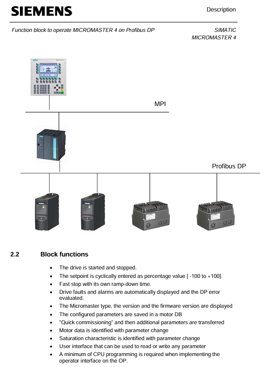
SIEMENS SIMATIC S7 300/400 operates MICROMASTER 4 (MM4) frequency converter through Profibus DP
Set value transmission: Loop the speed set value in the form of percentages from * * -100% to+100% * *, and any changes will take effect in real-time.
Status feedback: Output signals such as motor rotation direction (O-Right/O-Left), actual frequency (O-Actual_frequency, range -100% to+100%), and shutdown status (O-STOP).
SIEMENS SIMATIC S7 300/400 operates MICROMASTER 4 (MM4) frequency converter through Profibus DP
Core purpose and value of functional blocks
Inverter control
Implement motor start stop: supports regular start stop (dependent on P1120 ramp up time, P1121 ramp down time) and quick stop (dependent on P1135 OFF3 ramp down time).
Set value transmission: Loop the speed set value in the form of percentages from * * -100% to+100% * *, and any changes will take effect in real-time.
Status feedback: Output signals such as motor rotation direction (O-Right/O-Left), actual frequency (O-Actual_frequency, range -100% to+100%), and shutdown status (O-STOP).
Automatic debugging
Batch/Replacement Scenario Adaptation: When debugging multiple MM4 units in bulk or replacing a single faulty unit, there is no need for PG/PC or professional debugging software. The PLC can automatically complete the parameter configuration of the new MM4.
Simplified debugging process: including quick debugging (P0010=1), motor recognition (requires motor cold state), and saturation characteristic recognition (only supported by MM440).
parameter management
Full parameter read and write: Read and write all parameters of MM4 through PKW communication, and the OP (operation panel) only supports parameter reading.
Parameter backup: Store the debugged parameters in the PLC's parameter DB (data block) for easy recovery in the future.
Diagnostic function
Multi dimensional error monitoring: covering MM4 faults/alarms, Profibus DP errors, parameter transmission errors, and automatic debugging errors.
Historical data recording: stores the latest and historical fault/alarm information (such as the fault codes and values of the last 3 faults), supports fault reset (I_RESET_Corr).
Scope and Limitations of Application
3.1 Applicable Equipment
Equipment type, specific model/specification
MM4 frequency converter MM411 V1.10, MM420 V1.17, MM430 V2.00, MM440 V2.05
Controller SIMATIC S7 300 (CPU 313-2DP and above) S7 400、C7、SINUMERIK
3.2 Not Applicable Devices and Limitations
Not applicable to controllers: SIMATIC S7 200, SIMATIC S5.
Function limitation: The system does not monitor whether the startup signal (I_Enable) meets safety conditions, and users need to provide additional protection in the program.
Installation and configuration process
4.1 Scenario without Drive ES Basic and Starter
Hardware configuration: Set the Profibus DP address of MM4 (no need to reset to factory settings).
HW Config operation:
Start HW Config in Step 7 and configure PLC hardware.
Select "MICROMASTER 4" in the "PROFIBUS-DP/SIMOVERT Catalog" and specify the DP address.
Select slot 1 and configure PPO type as PPO1 (4 PKW+2 PZD).
Program loading:
Save and compile HW Config, download to PLC module.
Copy the program blocks and symbol table from the functional block example to the user program, adapt them, load them into the PLC, and start them.
Debugging startup: Call the MM4 diagnostic interface of OP to troubleshoot DP errors, enter the debugging interface to enter motor data, start automatic debugging (set I2 Enable=0, I2 Enable QC=1, IOU_ Parameters=1), and execute motor recognition after completion.
4.2 Scenarios with Drive ES Basic and Starter
Hardware configuration: Follow step 1 of section 4.1 to set the DP address of MM4.
HW Config operation:
Configure PLC and MM4, select the corresponding MM4 version (refer to the equipment nameplate, such as "A01/2.05" corresponding to version 2.0x).
Pre allocate PPO type as PPO1 (PKW+PZD-2/2), fill in the I/O address of MM4 (PKW starting address, PZD address is PKW address+8).
Program and OP adaptation:
Load the program block and symbol table in step 3 of section 4.1.
Install OP project and adapt to "MM4" and "ParameterDB" text lists.
Debugging startup: The first debugging can be completed through Starter, and the parameters can be entered into the parameter DB; or the OP debugging interface can be directly called, and the subsequent process is the same as step 4 in 4.1.
Detailed explanation of key functions
5.1 Definition of Control and Feedback Signals
Parameter Name Type Direction Unit/Range Description
The starting I/O address of the PKW area configured in the I-Address INT IN - HW Config
I-Enable BOOL IN - Variable frequency drive enable signal, can only be set when O-Drive-ready=1
I-Fast-STOP BOOL IN - Fast Shutdown Signal: 0=Fast Shutdown (using P1135), 1=Normal Shutdown (default can be set to 1)
Setpoint INT IN -100~+100 speed setting value (percentage)
Actual operating frequency INT OUT -100~+100 (percentage)
O-Drive-ready BOOL OUT - Inverter ready signal: must meet the requirements of "shutdown, I-Fast-STOP=1, no faults, no debugging in progress"
O-Fault BOOL OUT - MM4 fault signal (excluding data transmission errors)
O-Data_ error BOOL OUT - Parameter transmission/automatic debugging error signal
IOU_ Parameters BOOL IN/OUT - Start automatic debugging signal (user set 1 to start, clear 0 after FB is completed)
5.2 Automatic Debugging Process
5.2.1 Parameter DB adaptation
Motor data area: Enter the required parameters for quick debugging (P0010=1), using motor dataset 0 by default; Multiple parameter DBs need to be created for multiple datasets, which can be specified through Z_Sotor_data_SBNr.
Technical data area: Enter other parameters that are not quick debugging, support sub parameters (sub parameter 0 is the first, such as data [2] indicating the presence of sub parameters 0 and 1), and match the data type of the parameters.
5.2.2 Parameter input method
Operation steps for input method
Method 1: The frequency converter has been debugged and set to I2 Enable=0 and I2 Enable QC=1;
2. Set IOUR_Parameters=1 to start data reading;
3. O-Data_transfer_running=1 indicates that the transfer is in progress, and after completion, IOUR_Parameters will automatically clear 0.
Method 2: 1. Enter parameters directly on the OP interface (only display the parameters that need to be changed);
2. Use initial values for other parameters and support leaving the DB list empty (for easy OP indirect addressing).
5.2.3 Automatic Debugging Steps
Restore MM4 to factory settings.
Perform quick debugging (transfer motor data area parameters).
Transmission technology data area parameters.
Save the parameters to the EEPROM of MM4.
After debugging is completed, perform motor identification (ensuring that there are no errors during debugging and the motor is in a cold state).
5.3 Parameter transmission mechanism
Communication method: Based on PKW communication, it supports three parallel parameter read/write requests (Job_1~Job_3), which are executed in the order of Job_1 → Job_2 → Job_3.
Request block structure (taking Job_1 as an example):
|Parameter Name | Type | Initial Value | Description|
|Job_1. Parameter-N | INT | 0 | Target parameter number (e.g. 1002 represents fixed frequency 2)|
|Job_1. Index | INT | 0 | Sub parameter number (set 0 when there is no sub parameter, set the last sub parameter number when there are multiple sub parameters)|
|Job_1. Identifier | Byte | B # 16 # 0 | Operation type: 1=Read single parameter, 2=Write RAM, 3=Write EEPROM, 11=Read multiple sub parameters, etc|
|Job_1. Value_2~2 | DINT | L # 0 | Transferred parameter values (used as needed, such as using only Value_0 for a single parameter)|
Control signal: Job.RWRequest_1~3 are request trigger signals (user set 1 to start, clear 0 after FB is completed); Data_fault.Job.RWRequest_1~3 are error signals corresponding to the requests.
5.4 Diagnostic mechanism
5.4.1 Classification of Error Sources
Malfunctions/alarms of MM4 (such as overcurrent and overvoltage).
Fault of standard FC (SFC14/SFC15).
The functional block itself is malfunctioning.
Parameter transmission and automatic debugging errors.
5.4.2 Key diagnostic signals and displays
Parameter Name Type Direction Description
When there is an alarm for O-Warning BOOL OUT, it is 1
O-Fault BOOL OUT MM4 fault is 1 (excluding data errors)
Resetting signal: clearing MM4 fault and data error display, interrupting debugging process (without interrupting parameter transmission)
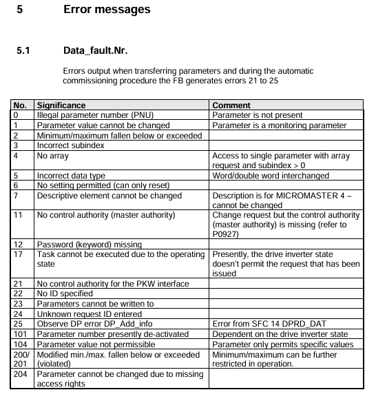
Data_fault.Nr. INT STAT error number (e.g. 0=illegal parameter number, 17=request execution not allowed in running state)
Data_fault.DP_Add_info HEX STAT DP error details (e.g. 8090=no module specified address, corresponding to SFC14/SFC15 error)
Error code description
6.1 Data_fault.Nr. (Parameter transmission and debugging errors)
Error Number Meaning Remarks
0 Illegal Parameter Number (PNU) parameter does not exist in MM4
The parameter value cannot be modified. This parameter is a monitoring type parameter and can only be read
17. Due to operational status, the task cannot be executed. The current MM4 status does not support this request (such as changing motor data during operation)
25 DP error needs to be viewed in conjunction with Data_fault.DP_Add_info for details
Parameter number 1001 is currently not activated and depends on the running status of MM4. It can be operated after activation
6.2 Data_fault.DP_Add_info (DP Error Supplement)
Meaning of Error Code (W # 16 #)
8090 specifies logical address without configuration module
80A0 recognized access error while accessing I/O
The target range length of 80B0 does not match the network data length configured in Step 7
6.3 Data_fault.Fault_Commission
Error Number Meaning Remarks
1001 DP error needs to be investigated for Profibus DP connection and address configuration
1002 automatic debugging data error parameter DB has errors (such as parameter values exceeding the range)
1007 MM4 model incorrectly configured MM4 model does not match the actual connected device
Functional Block Technical Data
Project specifications
Block type FB
Block Name MM4
Generate language STL
Local data 36 bytes
MC7 code length 3166 bytes
Load memory requirement 4244 bytes
Working memory requirement 3202 bytes
- OMRON
- ABB
- General Electric
- EMERSON
- Honeywell
- HIMA
- ALSTOM
- Rolls-Royce
- MOTOROLA
- Rockwell
- Siemens
- Woodward
- YOKOGAWA
- FOXBORO
- KOLLMORGEN
- MOOG
- KB
- YAMAHA
- BENDER
- TEKTRONIX
- Westinghouse
- AMAT
- AB
- XYCOM
- Yaskawa
- B&R
- Schneider
- KONGSBERG
- NI
- WATLOW
- ProSoft
- SEW
- ADVANCED
- Reliance
- TRICONEX
- METSO
- MAN
- Advantest
- STUDER
- DANAHER MOTION
- Bently
- Galil
- EATON
- MOLEX
- DEIF
- B&W
- ZYGO
- Aerotech
- DANFOSS
- Beijer
- Moxa
- Rexroth
- Johnson
- WAGO
- TOSHIBA
- BMCM
- SMC
- HITACHI
- HIRSCHMANN
- Application field
- XP POWER
- CTI
- TRICON
- STOBER
- Thinklogical
- Horner Automation
- Meggitt
- Fanuc
- Baldor
- SHINKAWA
- Other Brands
- UniOP
- KUKA
- Iba
- Beckhoff
- ADLINK
-
 Basler Electric DECS-250-CN1SN1N Digital Excitation Control System
 -
 Basler Electric BE1-700 E0N2X1N Digital Protective Relay
 -
 Basler Electric SR4A-2B15B3A Static Voltage Regulator 120VAC 50/60Hz
 -
 Basler Electric 9261402111 PCB Control Board 9346000033
 -
 Basler Electric BE28053-002 Transformer BE28053002
 -
 Basler Electric BE3-25A Auto Synchronizer B1D Sync Module
 -
 Basler Electric BE3-GPR Generator Protective Relay
 -
 Basler Electric SCP-250-G-60 VAR Power Factor Controller 9 1100 00 109
 -
 Basler Electric BE3-32-1S1N1 Reverse Power Relay 277V 5A
 -
 Basler Electric ACA1300-60GM Area Scan Camera 106200-17
 -
 Basler Electric UFOV 260 A Protection Module Specs
 -
 Basler Electric BE03303001 Control Module
 -
Basler Electric BE3-GPR-P1BVSF Generator Protective Relay
-
 Basler Electric BE1-87G Solid State Protective Relay Guide
 -
 BASLER ELECTRIC BE1-60 VOLTAGE BALANCE RELAY T176884
 -
 Basler Electric BE1-32R Protective Relay
 -
 Basler Electric 9022900-103 Transformer 6-7VA 60Hz
 -
 Basler Electric BE1-59-A4E-E1K-B1S3F Overvoltage Relay
 -
 Basler Electric KR2FF-M Voltage Regulator 9 1163 00 103
 -
 Basler Electric UFOV 260 A Protective Module
 -
 Basler Electric PCB Assembly 9059701100 919620
 -
 Basler Electric SR8A2B01A3E Static Voltage Regulator
 -
 Basler Electric SSR125-12 Static Voltage Regulator 9185900102
 -
 Basler Electric SSR 63-12 Static Voltage Regulator 600VAC
 -
 Basler Electric BE1-60 Solid State Protective Relay
 -
 Basler Electric BE3-47N/27-3A4N2 Voltage Relay 9320400101
 -
 Basler Electric BE1-59 Over Voltage Relay
 -
 Basler Electric DECS100-B15 Automatic Voltage Regulator
 -
 Basler Electric PRS250 Veri-Sync Relay 9088800102
 -
Basler Electric BE25927001 Current Transformer 1:34 Amp
-
Basler Electric 9170818100 Generator Differential Relay
-
 Basler Electric BE1-59N Solid State Ground Fault Overvoltage Relay
 -
 Basler Electric 1783 DC Current Transformer Coil 1200:5A
 -
Basler Electric BE1-67 Ground Directional Overcurrent Relay
-
 Basler Electric UFOV-260A Underfrequency Overvoltage Module
 -
 Basler Electric BE10493001 Control Module
 -
Basler Electric SSR125-12 Static Voltage Regulator Guide
-
 Basler Electric BE1810/U-2 Solid State Frequency Relay Guide
 -
 Basler Electric 9105100106 UFOV-250A Protector Guide
 -
 Basler Electric MOC2199 9072300-335 Relay Module Guide
 -
 Basler Electric 9289902106 Circuit Board
 -
Basler Electric BE1-32R Protective Relay A1E E1P BOS1P
-
 Basler Electric RAL6144-16GM GigE Line Scan Camera with Lens
 -
 Basler Electric BE3-49R-5I5A1 Temperature Relay
 -
 Basler Electric BE1-32R Power Relay B3E E1R A0N1F
 -
 Basler Electric SR4A2B06B3A Static Voltage Regulator Features
 -
 Basler Electric 9121000106 Manual Voltage Control MVC Guide
 -
Basler Electric SR32A-2B15B3E Static Voltage Regulator
-
 Basler Electric SR4A2B06B3A Static Voltage Regulator Guide
 -
Basler Electric 801A193F02 Hammond Transformer Module
-
 Basler Electric BE1-24 Volts Per Hertz Relay A1E F1J D1S0F
 -
 Basler Electric AEC63-7 Analog Excitation Controller 220-277V
 -
Basler Electric BE132R Power Relay T245579
-
 Basler Electric MVC 108 Manual Voltage Control 90 37000 102
 -
 Basler Electric 9022900-103 Control Transformer 6-7VA 60Hz
 -
 Basler Electric BE1-79M Plug Adapter 9170111102
 -
 Basler Electric 9 2007 00 100 Current Boost System CBS 305
 -
 Basler Electric SR4A2B01B3A Static Voltage Regulator 120V
 -
Basler Electric BE1-32R Power Solid State Relay E2E A10 A0N0F
-
Basler Electric PRS250 Veri-Sync Relay 9088800102
-
 Basler DECS 125-15-B2C Digital Excitation Control
 -
 Basler BE 13693 002 Transformer
 -
Basler BE1-59N Ground Fault Overvoltage Relay
-
 Basler BE1-79A Reclosing Relay
 -
Basler 9-1051-00-105 Overload Protection Module
-
 Basler BE1-32R Power Relay – Directional Overcurrent Guide
 -
 Basler 9319700103 BE3-27T/59T-3A1N3 Voltage Relay
 -
Basler BE1-87G Generator Differential Relay
-
 Basler BE3-25-1D1N4 9319100106 480V Relay
 -
 Basler SR8A2B07B3A Static Voltage Regulator
 -
 Basler Electric BE4-27/59 Over/Under Voltage Relay 307-2552
 -
Basler Electric SR32A2B05B3E Static Voltage Regulator
-
Basler Electric BE1-27 A3E C3J A1N6F Solid State Protective Relay
-
 Basler Electric 9174700-100 Excitation Limiter Generator
 -
Basler Electric BE1-87G Generator Differential Relay 09833
-
 Basler Electric 9310200100 Power Supply Module
 -
 Basler Electric TIEE1CD0N07 Control Module
 -
Basler Electric BE1-59N Ground Fault Relay T214750
-
Basler Electric SR8A2B10B3AX Static Voltage Regulator 9060200126
-
 Basler Electric SSR 125-12 Voltage Regulator
 -
 Rolls Royce H1111.0204 Ship Main Controller
 -
 Basler Electric BE3-32-3AC Reverse Power Relay 9 1376 00 105
 -
Basler Electric BE3-25-1A1N4 Synch Check Relay 9319100100
-
 Basler Electric SR4A-2B15B3A Static Voltage Regulator
 -
 Basler Electric SR4A-2B15B3E Static Voltage Regulator
 -
 Basler Electric 9170818100 Solid State Protective Relay
 -
 Basler Electric AEC63-7 Analog Excitation Controller
 -
Basler Electric 17483 Auxiliary Module
-
Basler Electric BE1-59 Over Voltage Relay
-
Basler Electric 21600-101 Control Module
-
 Basler Electric KR2F Generator Voltage Regulator 9056600100
 -
Basler BE1-CDS Current Differential System
-
 Basler Electric CBS 212 Current Boost System 9 2650 00 100
 -
 Basler Electric IFM-150 Firing Circuit Chassis
 -
 Basler Electric BE1-60 Voltage Balance Relay C1F A1P D0C3F
 -
Basler Electric BE1-32R Power Relay A2E D1R A0N0F
-
Basler Electric BE1-32R Power Relay A2E D1R A0N0F
-
 Basler Electric 8650C80G01 Isolation Transducer PCB Board
 -
 ETEL EA-P2M-300-4/7.5A-0100-01 AccurET Modular 300 Servo Drive
 -
Basler Electric 87T Transformer Differential Relay
-
Basler Electric BE-6868 Power Transformer 5950007559202
-
 Basler Electric PRS250 Veri-Sync Relay 9088800102
 -
 Basler Electric SCP-250-G-60 VAR Power Factor Controller
 -
 Basler DECS-150 AVR 1NS2V1N1S Voltage Regulator
 -
Basler UFOV 260A Under Frequency Overvoltage Module
-
 Basler MOC2 199 Motor Operated Control – Overview and Setup
 -
 Basler BE3-49R-5K5A1 Temperature Relay – Complete Guide
 -
Basler BE 20035 001 Transformer – Technical Data and Installation
-
Basler BE 02727 001 Transformer – Specifications and Usage
-
 Basler BE127 Under Voltage Relay – Features and Application Guide
 -
Basler CBS377 Current Boost System – Complete Technical Guide
-
Basler BE1-87G P/N 9170818100 Differential Relay – In-Depth Specs
-
Basler BE1-87G Generator Differential Relay – Technical Overview
-
Basler Electric SR4A2B16 SVR Static Voltage Regulator – Complete Guide
-
Basler Electric 9261500101 Power Supply Module
-
 Basler Electric AEM-2020 Analog Expansion Module
 -
Basler Electric DGC-2020 Digital Genset Controller 51BRBNEAH001
-
Basler Electric BE1-59N Ground Fault Overvoltage Relay
-
Basler Electric BE1-59N-A5E-E1L-N0S1F Neutral Overvoltage Relay
-
Basler Electric MOC2499 Motor Operator Control Potentiometer 9072300430
-
 Basler Electric BE1-50/51M Overcurrent Relay
 -
 Basler Electric 9148100106 MOC3502 Solid State Relay 250VDC 0.25A
 -
 Basler Electric CBS 212 Current Boost System 9265000100
 -
Basler Electric 10493002 Control Module
-
Basler BE1-32R D3E E1R A0N1F Power Relay
-
 Basler SR8A2B15B3A Static Voltage Regulator
 -
 Basler IFM-105 Firing Circuit Chassis 9324100105
 -
Basler SR4A2B05B3A Static Voltage Regulator


