
What are the core models of Yokogawa NFA series modules that support HART communication?
For connection with field equipment, refer to “Field Connection Specifications” (GS 34P02Q30-01E) and “STARDOM FCN/FCJ Installation Guide” (TI 34P02Q91-01E).
What are the core models of Yokogawa NFA series modules that support HART communication?
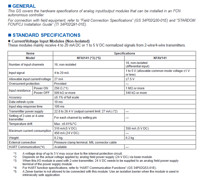
GENERAL
This GS covers the hardware specifications of analog input/output modules that can be installed in an FCN autonomous controller.
For connection with field equipment, refer to “Field Connection Specifications” (GS 34P02Q30-01E) and “STARDOM FCN/FCJ Installation Guide” (TI 34P02Q91-01E).
Module classification and core parameter summary
Module type represents model, channel quantity, core signal specifications, accuracy, power consumption (5V DC/24V DC), special characteristics
Non isolated current input NFAI141 16 channel (non isolated) input: 4~20mA ± 0.1% full-scale 310mA/450mA overcurrent protection, supports HART, 2/4-wire transmitter switching
Non isolated voltage input NFAV141 16 channel (differential) input: 1-5V (common mode voltage ± 1V) ± 0.1% full-scale 350mA/- input resistance ≥ 1M Ω
Isolation Current I/O (Channel Isolation) NFAI835 4-In/4-Out (Isolation) Input/Output: 4-20mA Input ± 0.1%, Output ± 0.3% 360mA/450mA Channel to Channel Voltage Resistance 500V AC, Supports HART
Isolation voltage output NFAV544 16 channel (isolated) output: -10~+10V ± 0.3% full-scale 860mA/- output fallback function, load resistance ≥ 5k Ω
TC input (isolated) NFAT141 16 channel (isolated) TC (J/K/E, etc.), mV (-100~150) ± 0.03%~± 0.032% full-scale 450mA/- reference compensation, burnout detection
Pulse input (channel isolation) NFAP135 8-channel (isolation) pulse frequency 0~10kHz -300mA/400mA 5 input modes, anti shake filtering
Frequency input (channel isolation) NFAF135 8-channel (isolation) frequency 0.1~10kHz 0.1% reading 300mA/400mA support contact/voltage pulse input
Key Function Description
Power supply requirements
Most modules require 24V DC power supply to the simulated on-site power terminals of the power module.
Transmitter power output: 22.8-26.4V (limited to 27mA) or 24.0-25.5V (limited to 25mA).
Special functional details
Overcurrent protection: NFAI141, NFAI143, NFAI135 and other modules are equipped.
Output fallback: Supports HOLD (hold fault output) or SETV (output specified value), detection time of 4 seconds, set by channel.
HART communication: NFAI141, NFAI841, NFAI143 and other models are supported, please refer to the dedicated document (GS 34P02Q53-01E).
Wire breakage detection: Some current output modules support detection threshold ≤ 0.65mA.
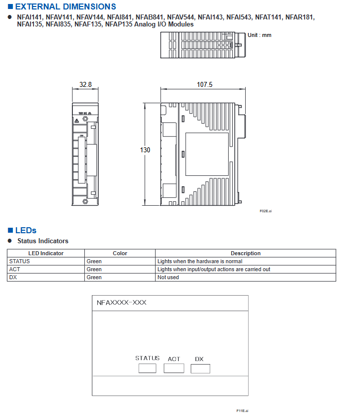
External connections and dimensions
Connection method: pressure clamping terminal, MIL connector cable (such as KMS40 cable).
Module size: uniformly 107.5mm × 32.8mm × 130mm (unit: mm).
Installation and usage restrictions
NFAT141 module special restrictions
To avoid the influence of radiant heat, heating units should not be installed below and should not be directly exposed to airflow.
Do not be adjacent to CPU modules (NFCP501/NFCP502) or power modules (NFPW44x).
It can only be installed adjacent to NFAT141, NFAR181, NFAV141, and NFAV144, and other modules need to have empty slots.
General installation requirements
It is necessary to confirm that the power consumption of the module does not exceed the rated output of the power module (5V DC or 24V DC).
Intrinsically safe applications require the use of isolation barriers and the connection of Zener barriers is prohibited.
Explosion proof selection should refer to the STARDOM FCN/FCJ Installation Guide.
Model coding rules
Meaning of suffix code
Communication functions: - S (standard type), - H (with HART communication).
Explosion proof rating: 5 (non explosion proof), E (explosion proof).
Type options: 0 (basic type), 1 (with ISA standard G3 option), 4 (wide temperature -40~+70 ℃).
Meaning of option codes
/13S00: Equipped with isolated simulated pressure clamping terminal (NFTI3S-00).
/13S10: Isolation analog pressure clamping terminal with surge absorber (NFTI3S-10).
/CCC01: Comes with MIL cable connector sheath (NFCCC01).
LED status indication
LED Name Color Description
When the STATUS green hardware is functioning properly, it lights up
ACT green lights up when executing input/output actions
DX green unused
Key issue
Question 1: What are the core models of NFA series modules that support HART communication? What power supply conditions need to be met?
Answer: The core models that support HART communication include NFAI141, NFAI841, NFAI143, NFAI543, NFAI135, and NFAI835; The power supply conditions are: when in use, a 24V DC power supply needs to be provided to the simulated on-site power terminal of the power module. The module itself consumes 5V DC (230~360mA) and 24V DC (250~540mA) currents. The output range of the transmitter power supply is 22.8-26.4V (limited to 27mA) or 24.0-25.5V (limited to 25mA), and it needs to match the requirements of the module model.
Question 2: What are the installation restrictions for NFAT141 module (TC input)? What are the core measurement accuracy and temperature drift indicators?
Answer: Installation restrictions: ① Avoid radiation heat, there is no heating unit below, and it is not affected by direct airflow; ② Not adjacent to the CPU module or power module; ③ It can only be installed adjacent to NFAT141, NFAR181, NFAV141, and NFAV144, and other modules need to have empty slots; Core parameters: ① Accuracy: thermocouple input ± 0.03% full range (-20~80mV), mV input ± 0.032% full range (-100~150mV); ② Temperature drift: thermocouple input Max ± 30ppm/° C, mV input Max ± 32ppm/° C.
Question 3: What is the output fallback function of NFA series modules? Which modules support this feature? How to configure?
Answer: The output fallback function is an output protection mechanism for the module when a fault is detected, which is divided into two modes: HOLD (maintain the output value when the fault occurs) and SETV (output specified value); The supporting modules include NFAI841, NFAB841, NFAI543, NFAV544, and NFAI835; Configuration method: ① First, select whether to enable fallback (Yes/No) for the module; ② Enable channel setting mode (HOLD/SETV); ③ The fault detection time is uniformly 4 seconds.
- ABB
- General Electric
- EMERSON
- Honeywell
- HIMA
- ALSTOM
- Rolls-Royce
- MOTOROLA
- Rockwell
- Siemens
- Woodward
- YOKOGAWA
- FOXBORO
- KOLLMORGEN
- MOOG
- KB
- YAMAHA
- BENDER
- TEKTRONIX
- Westinghouse
- AMAT
- AB
- XYCOM
- Yaskawa
- B&R
- Schneider
- KONGSBERG
- NI
- WATLOW
- ProSoft
- SEW
- ADVANCED
- Reliance
- TRICONEX
- METSO
- MAN
- Advantest
- STUDER
- DANAHER MOTION
- Bently
- Galil
- EATON
- MOLEX
- DEIF
- B&W
- ZYGO
- Aerotech
- DANFOSS
- Beijer
- Moxa
- Rexroth
- Johnson
- WAGO
- TOSHIBA
- BMCM
- SMC
- HITACHI
- HIRSCHMANN
- Application field
- XP POWER
- CTI
- TRICON
- STOBER
- Thinklogical
- Horner Automation
- Meggitt
- Fanuc
- Baldor
- SHINKAWA
- Other Brands
- UniOP
- KUKA
- Iba
-
 ABB 3BUS208720-001 Industrial Power Signal Interconnection Module
 -
 TMEIC KPAD-3122A LCD Display Keypad
 -
 Siemens 6SN1145-1BA02-0CA1 PLC
 -
 LAM 2004365 TURBO BYPASS PLC ASM
 -
 Omron CJ1W-CORT21 PLC Module
 -
 Euchner MGB-L2B-PNA-L-121853 Safety Switch
 -
 XPSMC32ZP Safety Controller
 -
 Schneider 9070T3000D33 PLC
 -
 Omron C200H-MAD01 AD DA Module
 -
 Omron NJ501-1320 CPU Controller
 -
 Honeywell C36TR1UA1000 Thermostat
 -
 Honeywell TC-RPDXX1 Power Supply Module
 -
 Fuji NW0E32-3 PLC Programmable Controller
 -
 ASM 2004219 Turbo Bypass ASM 107864 Module
 -
 Future IHDW-BLA4S-IM CNC MPG Handwheel
 -
 Wieland R1.180.0080.0 SA-OR-S1-4RK-A Safety Module
 -
 Reliance Electric 57C493 AutoMax Power Supply 376W
 -
 Siemens 3VT8563-2AA03-2KA2 MCCB 3VT8
 -
 B&R X20IF1072 CAN Bus Interface Module
 -
 Mitsubishi OSE253S2 Rotary Encoder
 -
 Mitsubishi NV630-SW 4P 500A Earth Leakage Breaker
 -
 Euchner MGB-L1B-PNA-R-121857 Safety Switch
 -
 Honeywell 900A01-0102 Analog Input Module
 -
 OMRON C500-ID219 Input Unit
 -
 Westinghouse EL3030R Current Limiter
 -
 CLA-2 3L Electric Lubrication Pump
 -
 Proface GP2501-TC41-24V HMI
 -
 Omron KM-N1-FLK Small Power Monitor
 -
 HPM 1D703-0040 Command 9000 Console Card
 -
 Siemens 3RW5074-6AB14 SIRIUS Soft Starter
 -
 Genie 75032 Limit Switch
 -
 OMRON C200H-SP001 Space Module
 -
 OMRON C200H-PS211 Power Supply Unit
 -
 OMRON C200H-OC222 Relay Output Unit
 -
 Keyence KV-8000SO 4221 CPU Module
 -
 Cincinnati Milacron 3-542-1079A Circuit Board
 -
 Beckhoff EL3124 Analog Input EtherCAT Terminal
 -
 KRONES BWU1703 0900853537 ASi PROFIBUS Gateway
 -
 Radio Energie RE0444 R1S 0.06 CA Tachogenerator
 -
 Mitsubishi GT1685M-STBA GOT1000 HMI
 -
 Siemens 6GK7342-5DA03-0XE0 CP 342-5 PROFIBUS
 -
 Allen Bradley 8520-PX-ASM3-EXEC2-63M Servo Module
 -
 Delta AH10PM-5A Programmable Controller
 -
 Siemens 3TK2805-0BB4 Safety Contactor Combination
 -
 EUCHNER HBA-079827 Pendant Station
 -
 CLC-2 4L PLC Lubrication Pump
 -
 KEYENCE GS-51P5 Safety Switch
 -
 AB 442G-MABH-R Safety Switch
 -
 GE Fanuc VersaMax PLC Module Set
 -
 Siemens 6ES7214-1HF40-0XB0 CPU 1214FC
 -
 Microchip DSPIC30F4011-30I/P DSC
 -
 FANUC A20B-2102-0081 I/O Link Module
 -
 Endress Hauser CLS15-B1M2A Conductivity Sensor
 -
 B&R 3AM050.6 Analog I/O Module
 -
 Fanuc A16B-2201-0320 MAIN-B CPU Board
 -
 Pilz 475650 PNOZ 1 Safety Gate Relay
 -
 Omron NSH5-AL001 Handheld HMI Terminal
 -
 Allen-Bradley 1756-OF8 Analog Output 8 Ch
 -
 Siemens 6SL3210-1SE31-0AA0 45kW Power Module
 -
 PMA TB45-110-00000-000 Temperature Limiter
 -
 PSR-SCP-24DC-ESD-5x1-1x2-300 Safety Relay
 -
 Pilz 774140 PZE 9 24V AC Safety Relay
 -
 Telemecanique TSXRKN82F 8 Slot Rack
 -
 Mitsubishi R16CPU iQ-R PLC CPU
 -
 Mitsubishi A2ACPU-R21-S1 PLC CPU
 -
 Omron NX-AD4208 Analog Input Unit
 -
 Schneider LMC802CAA10000 PacDrive 3 Controller
 -
 Reliance Electric 0-51874 Static Sequence Card
 -
 Pilz 787310 PNOZ X3P C Safety Relay
 -
 B&R X20CP1684 CPU Module
 -
 Siemens 6SN1145-1BB00-0FA1 Power Module
 -
 Beckhoff EL3174 Analog Input EtherCAT Terminal
 -
 CLC-2P 4L PLC Lubrication Pump System
 -
 Omron CJ1W-DA08C Analog Output Unit
 -
 Metso Automation D201776 ACN PO DC PLC Control Server Computer
 -
 GE AT868 AquaTrans Ultrasonic Flow Transmitter
 -
 ABB PFSA107-Z42 DTU Stressometer Digital Transmission Unit
 -
 ABB PFSA240 3BSE073476R1 Roll DC Supply Unit
 -
 Fanuc A16B-2201-0320 CPU MAIN Board
 -
 Pilz 475650 PNOZ 1 Safety Gate Relay
 -
 Omron NSH5-AL001 HMI Interface Unit
 -
 Allen-Bradley 1756-OF8 Analog Output Module
 -
 Siemens 6SL3210-1SE31-0AA0 Power Module 45kW
 -
 PMA TB45-110-00000-000 Temperature Limiter
 -
 PSR-SCP-24DC-ESD-5x1-1x2-300 Safety Relay
 -
 Pilz 774140 PZE 9 Safety Relay
 -
 Telemecanique TSXRKN82F PLC Rack Chassis
 -
 Mitsubishi R16CPU PLC CPU Module
 -
 OMRON C500-PS223-E Power Supply Module
 -
 Siemens 3VL4731-1DC36-0AA0 Circuit Breaker
 -
 Siemens 7ML5201-0EA0 Ultrasonic Level Transmitter
 -
 OMRON NQ3 NQ5 Touch Panel HMI
 -
 OMRON CJ1W-AD081-V1 Analog Input Module
 -
 OMRON NJ301-1100 Machine Automation Controller
 -
 B&R X20BC00G3 EtherCAT Bus Controller
 -
 Schneider ATV212HD22N4S Variable Speed Drive
 -
 B&R 8B0C0320HW00.002-1 Power Supply Module
 -
 Mitsubishi OSA105S2A Incremental Rotary Encoder
 -
 Pilz 777514 PNOZ XV3P Safety Relay
 -
 Gould AS-884A-111 Modicon 884 Controller
 -
 Siemens 6SC6130-0FE00 SIMODRIVE Control Card
 -
 Omron CV500-PS221 PLC Power Supply Module
 -
 ABB CM577-ETH AC500 PLC Ethernet Module
 -
 Omron NX-SIH400 Safety Input Unit NX Series
 -
 Omron NJ501-1300 Machine Automation Controller
 -
 Siemens 3VT8563-2AA03-2KA2 Molded Case Breaker
 -
 Pilz PNOZ m1p ETH 773103 Safety Controller
 -
 Omron CJ1H-CPU66H-R CJ1 Series CPU Module
 -
 ASI ASI533-S00 PLC Module S1
 -
 Mitsubishi AJ71C21-S1 Serial Module
 -
 Keyence IX-1000 Laser Sensor Amplifier
 -
 Siemens 6SN1145-1AA01-0AA1 Power Module
 -
 Siemens 3VA2340-5HL32-0AA0 MCCB 400A
 -
 Mitsubishi OSA104S Absolute Encoder
 -
 Siemens 6ES7350-1AH03-0AE0 FM 350-1 Counter
 -
 Siemens 6SE7038-6EK84-1JC2 IGD8 Gate Driver
 -
 Eaton EASY819-AC-RC Programmable Relay
 -
 Omron CPM1A-40CDT-D PLC 24V DC
 -
 Omron NA5-12W101B-V1 12-inch Programmable Terminal
 -
 Siemens 6ES7331-7KF02-0AB0 Analog Input SM 331
 -
 Moxa PTC-101-S-SC-HV Photoelectric Converter
 -
 Fanuc A20B-3300-0031 CNC Control Circuit Board
 -
 OMRON NA5-7W001B-V1 Programmable Terminal HMI
 -
 Parker AH385851U002 590C DC Drive Power Board
 -
 ABB 3BSE040662R1 AI830A Analog Input Module
 -
 DOLD BF9250.01/001 Solid State Relay
 -
 Siemens 6ES7331-7KF02-0AB0 SIMATIC S7-300 SM 331
 -
 ABB 07AC91 I6 GJR5252300R3101 Advant Controller 31


