
OMRON Z500 high-precision contour measurement system
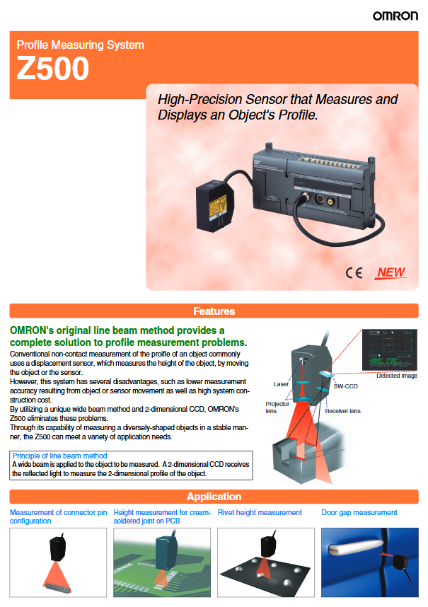
To solve the above problems, a line beam method based on wide beam projection and two-dimensional CCD image sensing has emerged. This method can obtain the complete two-dimensional contour information of a certain section of an object at once without the need for relative motion, and has the characteristics of high accuracy, high stability, and high efficiency.
OMRON Z500 high-precision contour measurement system
Introduction: Technical bottlenecks and alternative needs of traditional contour measurement
In the process of industrial automation manufacturing, high-precision measurement of object contours is a key link in quality control. Traditional non-contact measurement methods usually rely on point displacement sensors to obtain height data by moving the measured object or the sensor itself. However, this approach exposes multiple systemic flaws in practical applications:
Mechanical motion introduces errors: Whether it is moving objects or sensors, measurement accuracy will decrease due to factors such as clearance, vibration, and uneven speed in the guidance system.
The system construction cost is high: it requires precision motion platforms and complex control systems, which increases equipment investment and maintenance costs.
Low measurement efficiency: The point by point scanning method is difficult to meet the real-time detection requirements of high-speed production lines.
To solve the above problems, a line beam method based on wide beam projection and two-dimensional CCD image sensing has emerged. This method can obtain the complete two-dimensional contour information of a certain section of an object at once without the need for relative motion, and has the characteristics of high accuracy, high stability, and high efficiency.
The working principle and system composition of the line beam method
2.1 Technical Principles
The core of the line beam method is to project a wide beam (line laser) onto the surface of the object being measured, and the reflected light is received by a two-dimensional CCD. The system analyzes the position distribution of reflected light on the CCD, calculates the height information of each point on the surface of the object, and reconstructs the two-dimensional contour.
Compared to traditional displacement sensors that can only obtain the height of "points", the line beam method directly obtains the contour of "lines", avoiding errors caused by mechanical scanning. The key advantages of this technology include:
No need to move: The measurement can be completed when the object and sensor are relatively stationary.
Wide adaptability: suitable for specular reflection, diffuse reflection, surfaces of different colors and materials.
High speed response: Fixed sampling period, suitable for dynamic process monitoring.
2.2 System composition
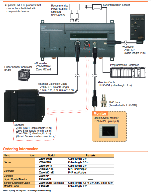
A typical line beam measurement system consists of the following components:
Sensor head: emits line laser and receives reflected light, with a built-in two-dimensional CCD.
Controller: processes image data, executes measurement algorithms, and outputs results.
Display screen (optional): Real time display of contour images, trend charts, numerical values, etc.
Cables and accessories: including sensor extension cables, monitoring cables, ferrite magnetic rings, etc.
The controller supports multiple input and output modes, including RS-232C, analog output (voltage or current), and digital IO trigger control. Its analog output resolution can reach 1/40000, with extremely high signal accuracy.
Detailed Product Series and Performance Parameter Interpretation
The following is a detailed specification of a typical line beam measurement system (such as OMRON Z500 series), covering key technical parameters such as measurement mode, distance, range, resolution, and light source type for different models.
3.1 Model Classification and Applicable Scenarios
According to the measurement distance and range, it is mainly divided into the following three sub models:
Model Mode Measurement Center Distance Measurement Range Applicable Scenarios
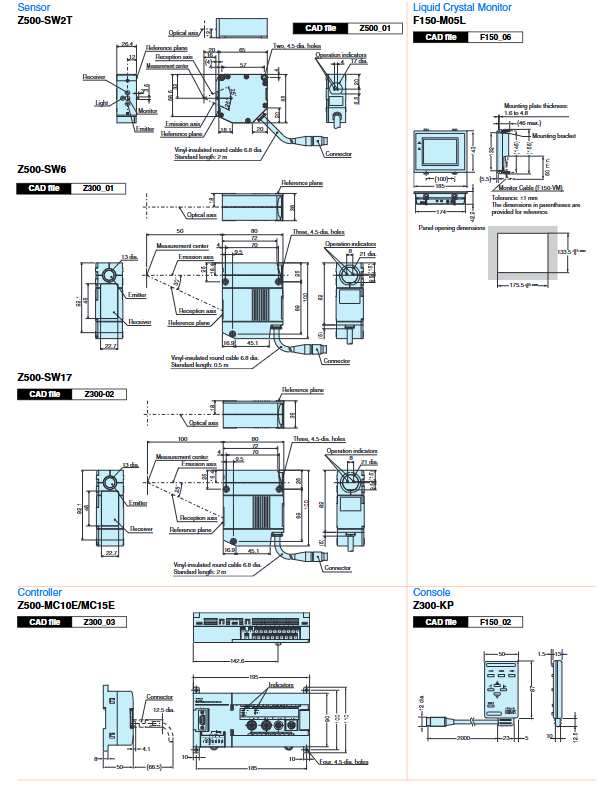
SW2T diffuse reflection/mirror reflection 5.2 mm/20 mm ± 0.8 mm/± 5 mm ultra precision close range detection
SW6 diffuse reflection/mirror reflection 50 mm/44 mm ± 4 mm/± 20 mm universal industrial testing
SW17 diffuse/mirror reflection 100 mm/94 mm ± 16 mm/± 16 mm long distance, wide range detection
3.2 Light source characteristics
SW2T: wavelength 650 nm, maximum output 1 mW, Class 2 laser.
SW6/SW17: wavelength 658 nm, maximum output 15 mW, Class 3B laser.
Note: Higher power lasers are available for special applications, please contact the supplier.
3.3 Beam size and measurement area
SW2T: 20 μ m × 4 mm (measurement area 2 mm)
SW6: 30 μ m × 24 mm (measurement area 6 mm)
SW17: 60 μ m × 45 mm (measurement area 17 mm)
3.4 Linearity and Resolution
Linearity: All models are ± 0.1% F.S. (full scale), but the reference material is different:
SW2T: Quartz glass (mirror) or SUS block (diffuse reflection)
SW6: SUS block
SW17: White alumina ceramic
Resolution:
SW2T: 0.25 μ m (average number of times 16)
SW6: 0.3 μ m (average number of times 64)
SW17:1.0 μ m (average number of times 64)
Attention: Resolution may decrease in strong magnetic field environments.
3.5 Sampling period and environmental adaptability
Fixed sampling period: 9.94 ms, suitable for real-time dynamic detection.
Temperature characteristics: 0.01% F.S./° C
Protection level:
SW2T:IP64
SW6/SW17: IP66 (better protection)
Work environment:
Temperature: 0-50 ° C
Humidity: 35-85% RH
Vibration: 10-150 Hz, double amplitude 0.35 mm
Illumination: Receiving surface illumination ≤ 3000 lx (incandescent lamp)
3.6 Other physical parameters
Cable length: SW2T (2 m), SW6 (0.5 m), SW17 (2 m)
Minimum bending radius: 68 mm
Weight: 600-800 g (including packaging)
Material: Die cast aluminum body, heat-resistant vinyl chloride cable, zinc alloy+brass connector
Four major monitoring modes and their engineering applications
In the actual testing process, the system provides four different data display methods for engineers to choose according to their needs:
4.1 Profile Monitor
Displaying the changes in contour over time in the form of 3D grayscale images is suitable for analyzing the dynamic evolution of cross-sectional height, such as changes in welding pool shape, uniformity of sealant application, etc.
4.2 Image Monitor
Simultaneously displaying measurement data and contour images facilitates on-site operators to intuitively understand the correspondence between measurement results and physical objects.
4.3 Digital Monitor
Simultaneously displaying the values of multiple measurement items, such as height difference, step height, edge position, etc., is suitable for numerical comparison in batch testing.
4.4 Trend Monitor
Display the trend of measurement data over time, suitable for process stability analysis, such as shrinkage changes during injection molding.
Controller functions and data processing capabilities
The controller is the computational core of the entire system and possesses the following key capabilities:
5.1 Measurement Items
Supports multiple measurement types:
height
Two point step height (Step: 2 pts)
Three point step height (Step: 3 pts)
Edge position
width
Edge center
Peak/valley value
5.2 Data Storage and Triggering
Storage points: up to 2048 points
Trigger method:
free running
External trigger 1/2
Automatic judgment output
5.3 Output Interface
RS-232C: Measurement value output
Terminal output: 11 point input (such as trigger, reset, D10-D17), 21 point output (D00-D019, GATE)
Analog output: ± 5 V (resolution 0.25 mV) or 4-20 mA (resolution 0.4 μ A)
5.4 Electrical and Environmental Parameters
Power supply: 21.6-26.4 VDC
Current consumption: ≤ 1 A (connected to two sensors)
Insulation resistance: ≥ 20 M Ω (100 VDC)
Voltage resistance: 1000 VAC, 1 minute
Noise resistance: 1500 Vp-p
Impact resistance: 200 m/s ²
5.5 Display specifications
Screen: 5.5-inch TFT color LCD
Resolution: 320 × 240
Input signal: NTSC composite video
Power supply: 20.4-26.4 VDC
Power consumption: approximately 700 mA
Installation, wiring, and laser safety regulations
6.1 Installation precautions
Sensors and controllers should be installed in an environment free from corrosive gases and strong magnetic field interference.
The grounding resistance must be less than 100 Ω.
The minimum bending radius of the cable is 68 mm to avoid signal interference.
6.2 Requirements for safe use of lasers
Due to the involvement of Class 2 or Class 3B lasers in the system, the following specifications must be strictly followed:
Strictly follow the operation manual to avoid direct exposure to the laser beam.
Ensure that the laser path is absorbed or terminated at the terminal to avoid the harm of reflected light.
If using a mirror reflective object, the path of the reflected light must be controlled.
Do not disassemble or remove the protective casing.
All repairs must be completed by the original factory or authorized personnel.
Laser warning labels must be clearly visible.
When used in different countries, comply with local laser safety regulations.
Common troubleshooting and engineering recommendations
7.1 Measurement value fluctuation or instability
Possible reasons:
Strong magnetic field interference
Multiple reflections caused by reflective surfaces
Excessive ambient lighting (>3000 lx)
Solution:
Increase the average number of measurements (e.g. from 16 to 64)
Use a light shield or change the measurement mode (mirror → diffuse reflection)
Adjust the sensor angle to avoid mirror reflection
7.2 Linearity exceeds specifications
Possible reasons:
The difference between the tested material and the calibration reference material is too large
Sensor lens contamination
Solution:
Re calibrate using standard blocks that are similar to the actual workpiece material
Clean the lens to avoid the influence of dust or oil stains
7.3 Unable to trigger or output abnormality
Possible reasons:
Mismatch in trigger signal level
Poor grounding of power supply
Solution:
Check the external trigger voltage range (should be compatible with the controller)
Confirm that the grounding resistance is ≤ 100 Ω
7.4 Error caused by temperature drift
Solution:
Use temperature compensation function (0.01% F.S./° C)
Using aluminum fixtures to stabilize heat conduction between sensors and the measured object
Application Cases and Selection Suggestions
8.1 Typical Applications
Coplanarity detection of electronic component pins: Use SW2T with a resolution of 0.25 μ m to detect the height difference of connector terminals.
Rubber sealing strip contour detection: using SW6, measuring width ± 20 mm, suitable for the reflection characteristics of soft materials.
Edge positioning of lithium battery electrode coating: using SW17, long working distance to avoid interference with the coating process.
8.2 Selection Suggestions
Reason for recommending the required model
Ultra high precision (μ m level) SW2T has the highest resolution and a small measurement range
General industrial testing SW6 balance resolution and measurement range
Large range/long-distance SW17 suitable for large workpieces or limited installation space
- ABB
- General Electric
- EMERSON
- Honeywell
- HIMA
- ALSTOM
- Rolls-Royce
- MOTOROLA
- Rockwell
- Siemens
- Woodward
- YOKOGAWA
- FOXBORO
- KOLLMORGEN
- MOOG
- KB
- YAMAHA
- BENDER
- TEKTRONIX
- Westinghouse
- AMAT
- AB
- XYCOM
- Yaskawa
- B&R
- Schneider
- Kongsberg
- NI
- WATLOW
- ProSoft
- SEW
- ADVANCED
- Reliance
- TRICONEX
- METSO
- MAN
- Advantest
- STUDER
- KONGSBERG
- DANAHER MOTION
- Bently
- Galil
- EATON
- MOLEX
- DEIF
- B&W
- ZYGO
- Aerotech
- DANFOSS
- Beijer
- Moxa
- Rexroth
- Johnson
- WAGO
- TOSHIBA
- BMCM
- SMC
- HITACHI
- HIRSCHMANN
- Application field
- XP POWER
- CTI
- TRICON
- STOBER
- Thinklogical
- Horner Automation
- Meggitt
- Fanuc
- Baldor
- SHINKAWA
- Other Brands
- UniOP
- KUKA
- Iba
-
 Omron CJ1G-CPU43H CPU Unit 30K Steps
 -
 OMRON C28P-EDR-D PLC Unit
 -
 SIEMENS S7-300 PLC System
 -
 Schneider TP400-PLC-1411 Board
 -
 Siemens 6FC5203-0AF00-0AA3 Panel
 -
 ALLEN BRADLEY 1754-L28BBB GuardPLC
 -
 Omron E6C3-AG5B-C Encoder
 -
 SCE M68-2000/5 CNC Controller
 -
 SCHNEIDER TM2ALM3LT Module
 -
 OMRON C200H-OV001 Voice Module
 -
 OMRON R88M-H30030 Servo Motor
 -
 Bosch RD500 Indramat Servo Drive RD51.2-4B
 -
 Siemens 6SE7090-0XX84-0AH2 T300 Module
 -
 Omron GRT1-TS2P SmartSlice Thermocouple Input
 -
 Xaar XP55500016 XUSB Drive Electronics
 -
 Siemens 6SL3210-1SE21-8UA0 PM340 Power Module
 -
 Mitsubishi GT2708-VTBA Touch Display 8.4 Inch
 -
 Pasaban Fast I/O MTC-3052 PLC Card
 -
 ABB ACS355-01U-02A4-2 VFD 0.37kW
 -
 Yamatake MAH20-PC2100 Processor Module
 -
 Allen Bradley 1774-P1 PLC Power Supply
 -
 Yaskawa SGDH-04AE-OY 400W Servo Driver
 -
 Omron CPH-X40DT1-D PLC CPU Unit
 -
 Pilz PNOZ mm0.2p Safety PLC Mini 772002
 -
 Siemens 6SL3555-OPR01-0AA0 Sinamics G110M Panel
 -
 Sanyo PLC-XTC50L LCD Projector
 -
 SCE M68-2000 2-Axis Motion Controller
 -
 Omron CS1W-CT021 High-Speed Counter Unit
 -
 Allen Bradley 100E400E 400A Contactor
 -
 Moeller LX-AK/FS-250IEC 250A Fuse Switch
 -
 OMRON FQM1-CM001 Coordinator Module
 -
 Landis+Gyr PCA2.N1 Power Supply
 -
 Mitsubishi Kakoki E-Series I/O Modules
 -
 OMRON R7A-CEA005S Servo Encoder Cable
 -
 Beckhoff EL1918-2200 TwinSAFE Terminal
 -
 OMRON F500-S1 Vision Sensor Camera
 -
 OMRON C200H-RM001-PV1 Master Unit
 -
 OMRON C60H-C7DR-DE-V1 PLC CPU
 -
 OMRON NX-PD1000 Power Supply Unit
 -
 OMRON CP1L-M60DT-D Micro PLC
 -
 Okuma 1911-2861 Graphic Circuit Board Module
 -
 Yaskawa SGDH-04AE-OY Servo Drive 400W
 -
 Omron R88D-UEP20V Servo Drive
 -
 Oliver 252RP Sakurai Mitsubishi Melsec PM-120M PLC
 -
 Electromatic Denmark SPS 200816 PLC
 -
 Omron FQM1 Flexible Motion Controller System
 -
 Pacer ZE4500 Axiomatic Motion Control Board
 -
 Delta Tau Turbo PMAC2 CPU Board USB Ethernet
 -
 Omron CQM1-CPU42-EV1 PLC CPU
 -
 Omron C500-NC222 Positioning Unit
 -
 ABB SACE TMAX T4 N 250 Circuit Breaker RC222
 -
 Mitsubishi FR A540L 75K E1 Inverter Drive
 -
 Siemens KSP M45 KSP M45 A66 Power Supply Module
 -
 Omron CQM1 TC102 Temperature Control Unit
 -
 Omron C200HW PRT21 Profibus DP Slave Unit
 -
 Yaskawa SGMGH 09DCA6S OY 850W Servo Motor 400V
 -
 Omron R88M UE75030V S1 AC Servo Motor
 -
 Omron C60H C5DR DE V1 PLC CPU Unit
 -
 Okuma 1911 2861 Graphic Card PLC Board Module
 -
 Omron R88D KN01H ML2 G5 Series Servo Drive
 -
 Laumas TLM8 Ethernet TCP/IP Load Cell Transmitter
 -
 Allen-Bradley 1771-NT2 Thermocouple Input Module
 -
 Siemens 6ES7135-0HF01-0XB0 Analog Output 4AO
 -
 Omron C60H-C6DR-DE-V1 Compact PLC
 -
 HMS Anybus AB7646-F Gateway Profibus to Profinet
 -
 Omron R7M-A10030-BS1 Servo Motor 100W Brake
 -
 Siemens 6SL3555-OPR01-0AA0 G110M Power Supply
 -
 Omron R88M-H10030-B AC Servo Motor 100W
 -
 Omron NJ301-1200 Sysmac NJ3 CPU EtherCAT
 -
 Toshiba H2218592 PLC Control Board Module
 -
 Omron R7A-CEA005S Servo Motor Encoder Cable 5M
 -
 TE.CO TFX 4G 1.5 Grey Cable
 -
 OMRON R88D-HT10 Servo Drive
 -
 OMRON CJ1G-CPU42H PLC CPU
 -
 MASS 106200 Industrial Monitor
 -
 OMRON CJ1W-AD041-V1 Analog Unit
 -
 Phoenix IBS PCI SC/I-T Board
 -
 OMRON ZFX-VS Vision Sensor
 -
 NAIS FP1-C72 PLC Controller
 -
 OMRON R88M-G75030H-BS2 Motor
 -
 SIEMENS A5E02625805-H2 PSU
 -
 Schweitzer SEL-2411 PAC Automation Controller
 -
 Siemens 5WG1-512-1AB11 Switching Actuator KNX
 -
 Stamford MX321-2 Automatic Voltage Regulator AVR
 -
 SCE M68-2000 Dual Axis CNC Servo Drive
 -
 ABB Bailey INNIS21 Network Interface Module
 -
 Omron CJ1W-F159 Loadcell Interface Module
 -
 GE Multilin MMII-PD-1-2-120 Motor Manager II
 -
 Yaskawa CIMR-VZ4A0018FAA VFD 5.5 7.5kW
 -
 Siemens 7SJ6001-5EA00-0DA0 Overcurrent Protection Relay
 -
 GE 531X300CCHAFM5 Drive Control PCB Board
 -
 Siemens 7SJ600 Overcurrent Protection Relay SIPROTEC
 -
 Siemens YSUW8 7683 C98043 A7002 Industrial PC Board
 -
 Omron 3G3MX2 A4055 E High Function Inverter Drive
 -
 Omron NB10W TW01B Interactive Display HMI Panel
 -
 Honeywell 30751044-008 Controller II ROM Board
 -
 Omron CJ1W IDP01 Combination Unit IO PLC
 -
 Omron C500 NC222 Position Control Unit PLC
 -
 Omron Z500 MC15E SW17R Vision System Controller
 -
 Sanyo Denki RS1A10AA RTA AC Servo Motor
 -
 Pilz PSS SB 3006 CN-A Compact Safety System PLC
 -
 OMRON C120-SI022 SYSMAC C120 Unit
 -
 SIEMENS 6SE9212-0DA40 MICROMASTER Inverter
 -
 ABB APBU-44C / APBU-44CE Branching Unit Kit
 -
 FANUC A20B-8100-0663 Mainboard
 -
 ABB 1SDA099907R1 Leakage Protection Relay
 -
 ABB IMMFP12 Multi-Function Module
 -
 OMRON CS1W-DA041 Analog Output Unit
 -
 Yaskawa SGMAS-08ACAHC61 Servo Motor
 -
 Benedetti 30.63/T090 3100MOT013_R1 Servo Motor
 -
 Omron C500-ASC02 ASCII Basic Unit Module
 -
 Yaskawa SGMGV-20DDL6F Servo Motor 1.8kW
 -
 ABB OITF-01C 64437496 D Control Board
 -
 TE.CO TFX 4G 1.5 Industrial Grey Cable
 -
 SCE M68-2000 Servo Drive Dual Axis
 -
 Omron C60H-C6DR-DE-V1 CPU Module PLC
 -
 Siemens 6SL3210-1SE21-8UA0 PM340 Power Module
 -
 Siemens 6GK7443-1EX30-0XE0 CP 443-1 Communications Processor
 -
 Siemens 6SL3210-1KE21-7AP1 SINAMICS G120C Drive
 -
 Phoenix UMK-32 RM/MR-G24/1/PLC Active Module
 -
 Omron NS5 SQ00B V2 HMI Touch Screen Industrial Terminal
 -
 Schneider TSX17 20 Micro PLC AEG Programmable Controller
 -
 Omron Z4M T30V2 Z4M H30V Laser Displacement Sensor System
 -
 Yaskawa SGMPH 04AAA61D OY 400W Servo Motor
 -
 Yaskawa CP 9300MC AC Servo Drive Motion Controller
 -
 Merlin Gerin VIP37PT48 Protection Relay Power Management
 -
 Yaskawa SGDH 05AE Sigma II Servo Driver 0.5kW
 -
 Rieter D90 DSP Autoleveller PLC Drawframe Control


