
Honeywell X-DCS3000 Digital Integrated System Manager
Honeywell X-DCS3000 Digital Integrated System Manager
Introduction: Challenges of Modern Public Broadcasting System and the Positioning of X-DCS3000
In complex environments such as airports, rail transit, large commercial complexes, and industrial plants, public address systems not only meet the needs of daily background music and broadcast notifications, but also undertake the task of guiding personnel evacuation in emergency situations such as fires. Traditional broadcasting systems have obvious shortcomings in audio source management, partition control, amplifier redundancy, fault detection, etc., especially when the main power supply is cut off or the amplifier channel fails, the reliability of the system is severely tested.
The Honeywell X-DCS3000 Digital Integrated System Manager (DCS), as the core unit of the X-618 public address system, provides a cost-effective and reliable solution for complex application scenarios through a highly integrated audio matrix architecture, dual power backup mechanism, 8+2 channel amplifier redundancy design, and networked scalability.
This article will provide a comprehensive technical analysis of X-DCS3000 from the aspects of system architecture, core functions, interface configuration, security mechanisms, common troubleshooting, and engineering deployment recommendations.
System Overview and Core Architecture
2.1 Equipment positioning and basic functions
The X-DCS3000 is a 1U rack mounted device (482 × 88 × 420 mm) with a net weight of 9.3 kg. As the "brain" of the X-618 system, it integrates the following functions:
Partition extension
Multi channel audio source support
Local storage of audio files
Network audio transmission
Broadcast scheduling and partition control
Real time monitoring and fault diagnosis
Its built-in audio matrix structure supports up to 8 amplifier channels and allows for 4 × 8 channel audio matrix switching, covering both local audio input and network audio routing.
2.2 Power backup and redundancy design
One of the most prominent safety features of X-DCS3000 is its dual power input:
Main power supply: AC 100-240V, 50/60Hz, built-in T2AL 250V fuse, providing overcurrent protection.
Backup power supply: DC 21.5V -28.5V (typical 24V), can be supplied by an external battery or DC power source.
When the main power supply experiences a short circuit fault or power outage, the system automatically switches to the backup DC power supply to ensure uninterrupted broadcasting. In addition, the device also provides a DC 24V/1A output, which can be used to power external auxiliary devices such as noise detectors.
2.3 Power amplifier redundancy strategy
The system supports 8 primary power amplifier channels and 2 backup power amplifier channels. By configuring the software, users can customize backup strategies:
1: 1 Backup: Each backup channel takes over a fixed main channel.
N: 1 Backup: Two backup channels can take over any faulty main channel.
When any main power amplifier malfunctions (such as overheating, overload, output short circuit), DCS automatically detects and routes the signal to the backup power amplifier, while outputting a fault alarm through dry contacts.
Detailed explanation of input and output interfaces and engineering wiring
3.1 Audio Input Interface
The device provides multiple audio input methods:
Interface type, quantity, technical parameters, purpose
Auxiliary input AUX1 10 dBV (1V), 10k Ω CD/DVD, mixing console and other line levels
Auxiliary input AUX2/3 2-40 dBV~0 dBV, 10k Ω microphone or low-level signal, supports phantom power supply
Network A/D audio input 4 10/100M Ethernet from X-618 network components or external IP audio source
DCL input has 8 channels, with up to 5 modules per channel that can be connected to noise detectors and EOL terminal modules for automatic volume control (AVC) and line end monitoring
Engineering Tip: The AUX2/3 input can be separately set for gain and phantom power (+48V), suitable for condenser microphones. If you need to connect a long-distance microphone, it is recommended to use shielded twisted pair cables and avoid sharing them with strong electrical cables.
3.2 Audio output interface
Speaker circuit output: 8 channels, each with 70V constant voltage output, maximum load power of 250W/channel. Support line fault detection (short circuit, open circuit).
Auxiliary output: 2 channels, 1.2V (<1.6 dBV), used to connect additional amplifiers or area extenders.
Recording output: 1 channel, 0 dBV, constant level, compatible with external recording devices.
3.3 Control and Status Interface
Dry contact input: 8 channels, can be connected to the relay output of the fire alarm controller (FACP). When any input is activated, DCS triggers emergency evacuation voice according to the preset priority.
Dry contact output: 8 channels, each providing NO, NC, COM contacts, with a maximum switching capacity of 250V AC/30V DC, 2.5A. Can be used to control external indicator lights, access control release devices, backup amplifier startup, etc.
RS-485 port: Connect to X-618 configuration software or remote control panel (such as X-NPMS).
Ethernet interface: 4 10/100M adaptive ports, supporting switch cascade or ring network connection, convenient for expanding partitions.
- ABB
- General Electric
- EMERSON
- Honeywell
- HIMA
- ALSTOM
- Rolls-Royce
- MOTOROLA
- Rockwell
- Siemens
- Woodward
- YOKOGAWA
- FOXBORO
- KOLLMORGEN
- MOOG
- KB
- YAMAHA
- BENDER
- TEKTRONIX
- Westinghouse
- AMAT
- AB
- XYCOM
- Yaskawa
- B&R
- Schneider
- Kongsberg
- NI
- WATLOW
- ProSoft
- SEW
- ADVANCED
- Reliance
- TRICONEX
- METSO
- MAN
- Advantest
- STUDER
- KONGSBERG
- DANAHER MOTION
- Bently
- Galil
- EATON
- MOLEX
- DEIF
- B&W
- ZYGO
- Aerotech
- DANFOSS
- Beijer
- Moxa
- Rexroth
- Johnson
- WAGO
- TOSHIBA
- BMCM
- SMC
- HITACHI
- HIRSCHMANN
- Application field
- XP POWER
- CTI
- TRICON
- STOBER
- Thinklogical
- Horner Automation
- Meggitt
- Fanuc
- Baldor
- SHINKAWA
- Other Brands
- UniOP
- KUKA
- Iba
-
 Omron CJ1G-CPU43H CPU Unit 30K Steps
 -
 OMRON C28P-EDR-D PLC Unit
 -
 SIEMENS S7-300 PLC System
 -
 Schneider TP400-PLC-1411 Board
 -
 Siemens 6FC5203-0AF00-0AA3 Panel
 -
 ALLEN BRADLEY 1754-L28BBB GuardPLC
 -
 Omron E6C3-AG5B-C Encoder
 -
 SCE M68-2000/5 CNC Controller
 -
 SCHNEIDER TM2ALM3LT Module
 -
 OMRON C200H-OV001 Voice Module
 -
 OMRON R88M-H30030 Servo Motor
 -
 Bosch RD500 Indramat Servo Drive RD51.2-4B
 -
 Siemens 6SE7090-0XX84-0AH2 T300 Module
 -
 Omron GRT1-TS2P SmartSlice Thermocouple Input
 -
 Xaar XP55500016 XUSB Drive Electronics
 -
 Siemens 6SL3210-1SE21-8UA0 PM340 Power Module
 -
 Mitsubishi GT2708-VTBA Touch Display 8.4 Inch
 -
 Pasaban Fast I/O MTC-3052 PLC Card
 -
 ABB ACS355-01U-02A4-2 VFD 0.37kW
 -
 Yamatake MAH20-PC2100 Processor Module
 -
 Allen Bradley 1774-P1 PLC Power Supply
 -
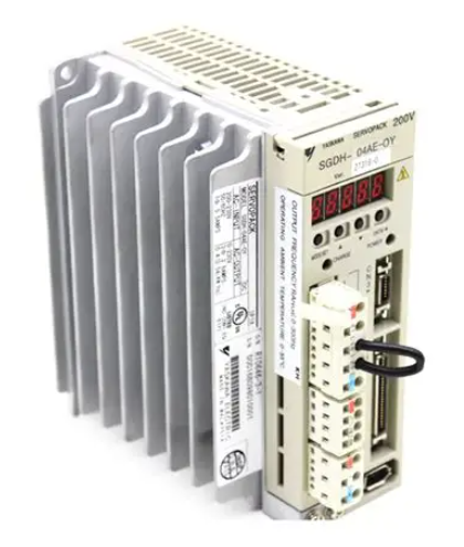 Yaskawa SGDH-04AE-OY 400W Servo Driver
 -
 Omron CPH-X40DT1-D PLC CPU Unit
 -
 Pilz PNOZ mm0.2p Safety PLC Mini 772002
 -
 Siemens 6SL3555-OPR01-0AA0 Sinamics G110M Panel
 -
 Sanyo PLC-XTC50L LCD Projector
 -
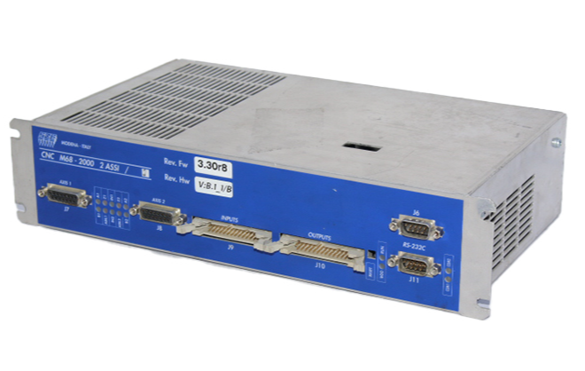
 SCE M68-2000 2-Axis Motion Controller
 -
 Omron CS1W-CT021 High-Speed Counter Unit
 -
 Allen Bradley 100E400E 400A Contactor
 -
 Moeller LX-AK/FS-250IEC 250A Fuse Switch
 -
 OMRON FQM1-CM001 Coordinator Module
 -
 Landis+Gyr PCA2.N1 Power Supply
 -
 Mitsubishi Kakoki E-Series I/O Modules
 -
 OMRON R7A-CEA005S Servo Encoder Cable
 -
 Beckhoff EL1918-2200 TwinSAFE Terminal
 -
 OMRON F500-S1 Vision Sensor Camera
 -
 OMRON C200H-RM001-PV1 Master Unit
 -
 OMRON C60H-C7DR-DE-V1 PLC CPU
 -
 OMRON NX-PD1000 Power Supply Unit
 -
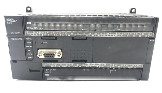
 OMRON CP1L-M60DT-D Micro PLC
 -
 Okuma 1911-2861 Graphic Circuit Board Module
 -
 Yaskawa SGDH-04AE-OY Servo Drive 400W
 -
 Omron R88D-UEP20V Servo Drive
 -
 Oliver 252RP Sakurai Mitsubishi Melsec PM-120M PLC
 -
 Electromatic Denmark SPS 200816 PLC
 -
 Omron FQM1 Flexible Motion Controller System
 -
 Pacer ZE4500 Axiomatic Motion Control Board
 -
 Delta Tau Turbo PMAC2 CPU Board USB Ethernet
 -
 Omron CQM1-CPU42-EV1 PLC CPU
 -
 Omron C500-NC222 Positioning Unit
 -
 ABB SACE TMAX T4 N 250 Circuit Breaker RC222
 -
 Mitsubishi FR A540L 75K E1 Inverter Drive
 -
 Siemens KSP M45 KSP M45 A66 Power Supply Module
 -
 Omron CQM1 TC102 Temperature Control Unit
 -
 Omron C200HW PRT21 Profibus DP Slave Unit
 -
 Yaskawa SGMGH 09DCA6S OY 850W Servo Motor 400V
 -
 Omron R88M UE75030V S1 AC Servo Motor
 -
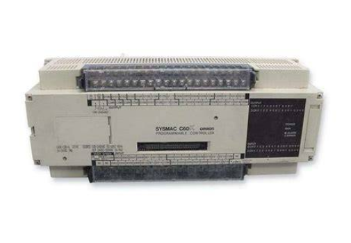 Omron C60H C5DR DE V1 PLC CPU Unit
 -
 Okuma 1911 2861 Graphic Card PLC Board Module
 -
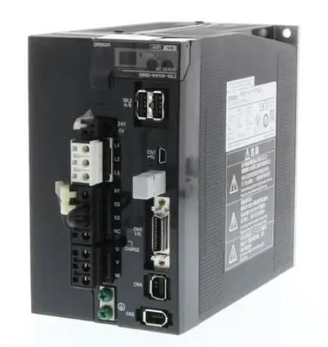
 Omron R88D KN01H ML2 G5 Series Servo Drive
 -
 Laumas TLM8 Ethernet TCP/IP Load Cell Transmitter
 -
 Allen-Bradley 1771-NT2 Thermocouple Input Module
 -
 Siemens 6ES7135-0HF01-0XB0 Analog Output 4AO
 -
 Omron C60H-C6DR-DE-V1 Compact PLC
 -
 HMS Anybus AB7646-F Gateway Profibus to Profinet
 -
 Omron R7M-A10030-BS1 Servo Motor 100W Brake
 -
 Siemens 6SL3555-OPR01-0AA0 G110M Power Supply
 -
 Omron R88M-H10030-B AC Servo Motor 100W
 -
 Omron NJ301-1200 Sysmac NJ3 CPU EtherCAT
 -
 Toshiba H2218592 PLC Control Board Module
 -
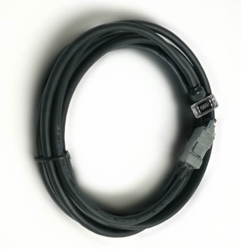 Omron R7A-CEA005S Servo Motor Encoder Cable 5M
 -
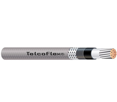 TE.CO TFX 4G 1.5 Grey Cable
 -
 OMRON R88D-HT10 Servo Drive
 -
 OMRON CJ1G-CPU42H PLC CPU
 -
 MASS 106200 Industrial Monitor
 -
 OMRON CJ1W-AD041-V1 Analog Unit
 -
 Phoenix IBS PCI SC/I-T Board
 -
 OMRON ZFX-VS Vision Sensor
 -
 NAIS FP1-C72 PLC Controller
 -
 OMRON R88M-G75030H-BS2 Motor
 -
 SIEMENS A5E02625805-H2 PSU
 -
 Schweitzer SEL-2411 PAC Automation Controller
 -
 Siemens 5WG1-512-1AB11 Switching Actuator KNX
 -
 Stamford MX321-2 Automatic Voltage Regulator AVR
 -
 SCE M68-2000 Dual Axis CNC Servo Drive
 -
 ABB Bailey INNIS21 Network Interface Module
 -
 Omron CJ1W-F159 Loadcell Interface Module
 -
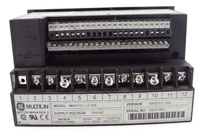 GE Multilin MMII-PD-1-2-120 Motor Manager II
 -
 Yaskawa CIMR-VZ4A0018FAA VFD 5.5 7.5kW
 -
 Siemens 7SJ6001-5EA00-0DA0 Overcurrent Protection Relay
 -
 GE 531X300CCHAFM5 Drive Control PCB Board
 -
 Siemens 7SJ600 Overcurrent Protection Relay SIPROTEC
 -
 Siemens YSUW8 7683 C98043 A7002 Industrial PC Board
 -
 Omron 3G3MX2 A4055 E High Function Inverter Drive
 -
 Omron NB10W TW01B Interactive Display HMI Panel
 -
 Honeywell 30751044-008 Controller II ROM Board
 -
 Omron CJ1W IDP01 Combination Unit IO PLC
 -
 Omron C500 NC222 Position Control Unit PLC
 -
 Omron Z500 MC15E SW17R Vision System Controller
 -
 Sanyo Denki RS1A10AA RTA AC Servo Motor
 -
 Pilz PSS SB 3006 CN-A Compact Safety System PLC
 -
 OMRON C120-SI022 SYSMAC C120 Unit
 -
 SIEMENS 6SE9212-0DA40 MICROMASTER Inverter
 -
 ABB APBU-44C / APBU-44CE Branching Unit Kit
 -
 FANUC A20B-8100-0663 Mainboard
 -
 ABB 1SDA099907R1 Leakage Protection Relay
 -
 ABB IMMFP12 Multi-Function Module
 -
 OMRON CS1W-DA041 Analog Output Unit
 -
 Yaskawa SGMAS-08ACAHC61 Servo Motor
 -
 Benedetti 30.63/T090 3100MOT013_R1 Servo Motor
 -
 Omron C500-ASC02 ASCII Basic Unit Module
 -
 Yaskawa SGMGV-20DDL6F Servo Motor 1.8kW
 -
 ABB OITF-01C 64437496 D Control Board
 -
 TE.CO TFX 4G 1.5 Industrial Grey Cable
 -
 SCE M68-2000 Servo Drive Dual Axis
 -
 Omron C60H-C6DR-DE-V1 CPU Module PLC
 -
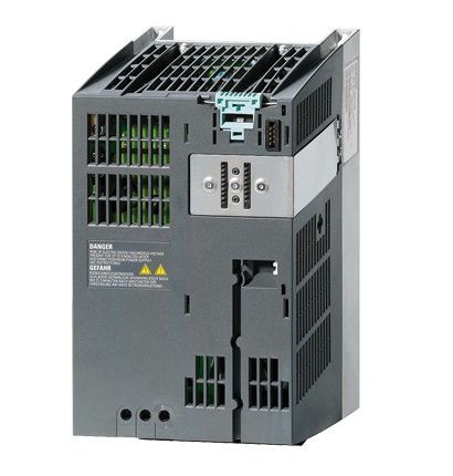 Siemens 6SL3210-1SE21-8UA0 PM340 Power Module
 -
 Siemens 6GK7443-1EX30-0XE0 CP 443-1 Communications Processor
 -
 Siemens 6SL3210-1KE21-7AP1 SINAMICS G120C Drive
 -
 Phoenix UMK-32 RM/MR-G24/1/PLC Active Module
 -
 Omron NS5 SQ00B V2 HMI Touch Screen Industrial Terminal
 -
 Schneider TSX17 20 Micro PLC AEG Programmable Controller
 -
 Omron Z4M T30V2 Z4M H30V Laser Displacement Sensor System
 -
 Yaskawa SGMPH 04AAA61D OY 400W Servo Motor
 -
 Yaskawa CP 9300MC AC Servo Drive Motion Controller
 -
 Merlin Gerin VIP37PT48 Protection Relay Power Management
 -
 Yaskawa SGDH 05AE Sigma II Servo Driver 0.5kW
 -
 Rieter D90 DSP Autoleveller PLC Drawframe Control


