
TEKTRONIX P6022 Current Probe
Auxiliary accessories BNC "T" type adapter, 50 Ω precision coaxial cable (36 inches), BNC to double banana head adapter, calibration fixture Tektronix corresponding models (see Table 6)
2. Core validation projects (including calculation methods)
(1) Mid frequency accuracy test (50 kHz)
Qualification criteria for step calculation method
1. Set the terminal to 1 mA/mV, calibrate the generator output to 50 kHz, 5 V p-p, connect BNC "T" → DMM, record the reading M1 I test=M1/50 Ω (test current). 2. Disconnect the DMM from "T", connect the probe+terminal, calibrate the probe clamp fixture, record the DMM reading M2% Error=[(M2 − I test)/I test] × 100 ± 3%
3. Set the terminal to 10 mA/mV, repeat step 2, and record the DMM reading M3% Error=[(10 × M3 − I test)/I test] × 100 ± 3%
(2) Low frequency bandwidth test
Qualification criteria for sensitivity gear step calculation method
1 mA/mV 1. Measure the output M1 at 50 kHz; 2. Set the generator to 8.5 kHz and measure the output M2 low-frequency ratio=M2/M1 ≥ 0.707
10 mA/mV 1. Measure the output of M3 at 50 kHz; 2. Set the generator to 935 Hz and measure the low frequency ratio of M4 output=M4/M3 ≥ 0.707
(3) High frequency bandwidth testing
Qualification criteria for sensitivity gear step calculation method
1 mA/mV. Set the oscilloscope to 20 mV/div and measure the amplitude M1 at 50 kHz. 2. Set the generator to 100 MHz and measure the amplitude M2. High frequency ratio=M2/M1 ≥ 0.707
10 mA/mV. 1. Set the oscilloscope to 2 mV/div and measure the amplitude M3 at 50 kHz. 2. Set the generator to 120 MHz and measure the amplitude M4. High frequency ratio=M4/M3 ≥ 0.707
3. Calibration adjustment (if verification fails)
Remove terminal cover: Use a small screwdriver to gently pry open the top snap cover of the terminal (keep the bottom cover).
Oscilloscope settings: CH1, DC coupling, 2 mV/div, 4-5 ns/div, average 5-10 times, trigger set AC, positive slope.
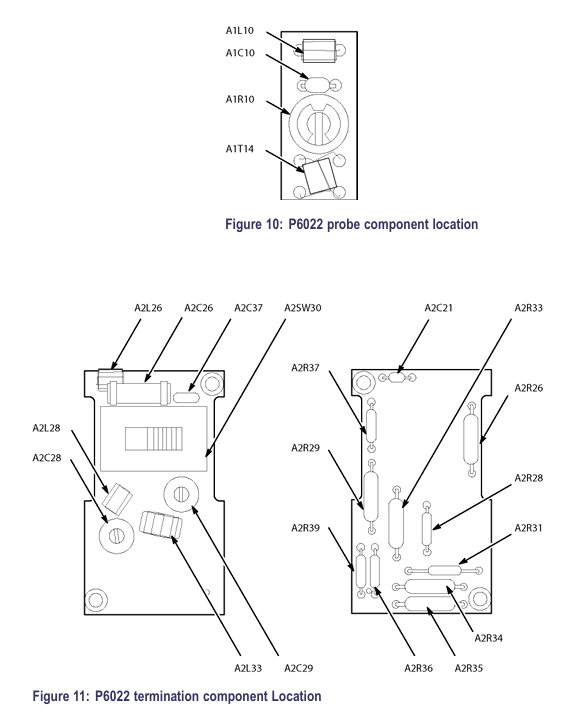
Adjust parameters: calibrate the generator to output a 1 V p-p fast edge signal and connect it to the calibration fixture; Adjust the C28 and C29 capacitors of the terminal and the R10 resistance of the probe to minimize waveform distortion and ensure optimal flat top response.
Maintenance and Repair
1. Daily maintenance
Cleaning: Wipe the probe body with a damp cloth; Clean the magnetic core with cotton swabs soaked in isopropanol (solvents such as benzene, toluene, acetone, etc. are prohibited); Do not soak or use abrasives.
Lubrication: The slider component can only be coated with a small amount of silicon-based grease, and petroleum based grease is prohibited; Lubrication is prohibited on the contact surface of the magnetic core.
Inspection: Regularly check the wear of the slider and the cleanliness of the magnetic core contact surface (dirt can reduce low-frequency response).
2. Disassembly and maintenance
(1) Probe disassembly (requires soldering iron)
Pull back the strain relief boot, gently pry on the probe body and remove it forward.
Take out the ball bearing and spring retainer, and remove the upper half of the slider, spring, and transformer.
Remove the grounding terminal of the circuit board and gently remove the circuit board, transformer, and cable components (to avoid damaging the cable solder joints).
(2) Terminal maintenance
Replace connector: remove cover → protect circuit with heat sink → solder off old connector → replace with new connector → solder reset.
Replace the circuit board: Remove the front and rear covers → solder off the connector wires → remove the circuit board screws → assemble in reverse after replacement.
3. List of replaceable parts (core)
Electrical components (excerpt from Table 10)
Component Number Tektronix Part Number Name and Description
A1 670-1112-00 Probe Circuit Board Component
A2 011-0106-00 P6022 Coaxial Terminal
A1T1 120-0603-00 Current Transformer
A2C28/A2C29 281-0123-00 Variable capacitor (5-25 PF, 100 V)
Mechanical components (excerpt from Table 11)
Drawing number/index Tektronix part number name and description quantity
12-1 204-0360-01 Probe Upper Shell 1
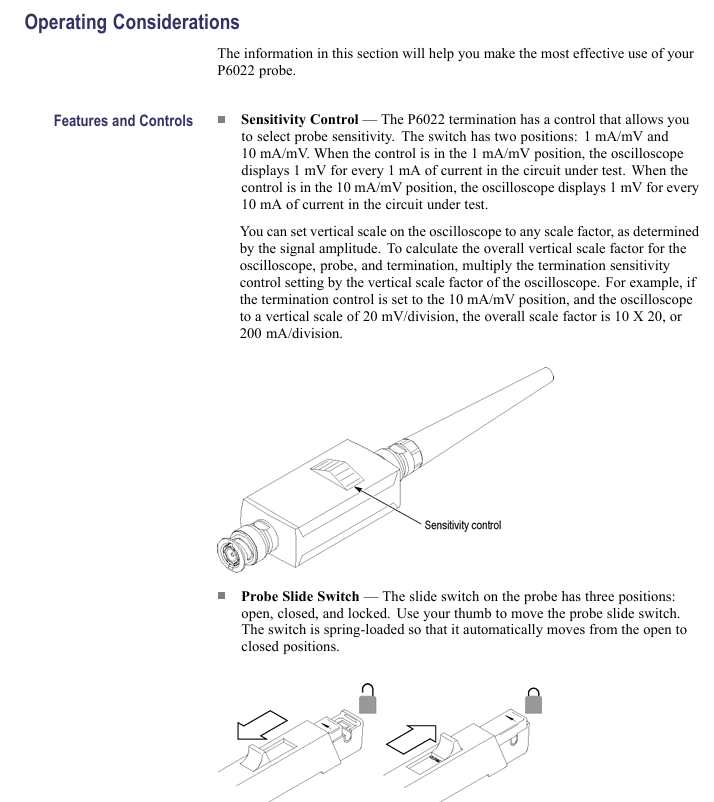
12-3 351-0174-00 Probe Slide (Acetal Material) 1
12-9 175-1027-00 RF Cable Assembly (62.5 Ω, 60 inches) 1
12-18 196-3120-01 Probe Grounding Wire (23 AWG, 6 inches) 1
- OMRON
- ABB
- General Electric
- EMERSON
- Honeywell
- HIMA
- ALSTOM
- Rolls-Royce
- MOTOROLA
- Rockwell
- Siemens
- Woodward
- YOKOGAWA
- FOXBORO
- KOLLMORGEN
- MOOG
- KB
- YAMAHA
- BENDER
- TEKTRONIX
- Westinghouse
- AMAT
- AB
- XYCOM
- Yaskawa
- B&R
- Schneider
- KONGSBERG
- NI
- WATLOW
- ProSoft
- SEW
- ADVANCED
- Reliance
- TRICONEX
- METSO
- MAN
- Advantest
- STUDER
- DANAHER MOTION
- Bently
- Galil
- EATON
- MOLEX
- DEIF
- B&W
- ZYGO
- Aerotech
- DANFOSS
- Beijer
- Moxa
- Rexroth
- Johnson
- WAGO
- TOSHIBA
- BMCM
- SMC
- HITACHI
- HIRSCHMANN
- Application field
- XP POWER
- CTI
- TRICON
- STOBER
- Thinklogical
- Horner Automation
- Meggitt
- Fanuc
- Baldor
- SHINKAWA
- Other Brands
- UniOP
- KUKA
- Iba
- Beckhoff
- ADLINK
-
 GE Fanuc VMIVME-5588 High-speed Reflective Memory Board
 -
 VMIC VMIVME-5565 Reflective Memory Board
 -
 VMIC VMIVME-2127 Voltage Source Digital Output Board
 -
 VMIC VMIVME 4512 Analog VME Process PCB Assembly
 -
 GE Fanuc VMIVME-3122-022 Analog I/O Module
 -
 VMIC VMIVME 5576 High Speed Fiberoptic Network Board
 -
 FANUC VMIVME-7452 VMEbus Analog I/O Board
 -
 FANUC VMIVME-2210 VMEbus Digital Output Board
 -
 FANUC VMIVME-7750-734000 VMEbus Single Board Computer
 -
 VMIC VMIVME 2210 VMEbus DO 28V Digital Output Board
 -
 VMIC VMIVME DR11W VMEbus DMA Interface Module
 -
 VMIC VMIVME-2536-200 5V Optically Coupled Digital I/O Board
 -
 VMIC VME-7754 VMIVMF7754-259000 VMEbus Control Card
 -
 VMIC 2170A VME Interface Board
 -
 GE VMIC PMC-5565PIORC-210000 Reflective Memory PMC Node Card
 -
 VMIC VMIVME-7750-750000 VME Single Board Computer
 -
 VMIC VMIVME-7751 VME Single Board Computer
 -
 VMIC 332-004512 Analog VME Process Board
 -
 VMIC VMIVME2528 VME Interface Board
 -
FANUC VMIVME-2120 VME Bus Interface Board
-
 FANUC VMIVME-2540 VME Bus Interface Board
 -
 FANUC VMIVME-3230 VME Bus Interface Board
 -
 FANUC VMIVME-4514 VME Bus Interface Board
 -
 ETEL DSB2S154-211E-000H Servo Amplifier
 -
 ETEL DSCQT112-111-000 Motion Control Module
 -
 ETEL LMG20-050-3QB-211A Servo Motor – High Torque Linear
 -
 ETEL EU-LCP-0-0-1000-01 Communication Card
 -
 ETEL DSA2P174ZA-033A Servo Amplifier Driver
 -
 ETEL EA-P2M-400-15/40A-0100-00 Servo Driver
 -
 ETEL DSC2P152-111-000 Servo Drive Amplifier
 -
 ETEL LMS15-050-3UA-209A Linear Motor
 -
ETEL DSC2P152-111D-000A Controller
-
 ETEL DSB2P131-111E-000B Digital Servo Amplifier Position Controller
 -
 ETEL DSO-PWR111C-000B Power Supply Module
 -
 ETEL DSCDP324-321F-000C Servo Driver
 -
 ETEL DSC2P152-111B-000D Controller
 -
 ETEL DSB2P142-111E-000H Circuit Board
 -
 ETEL LMG05-030-3QA-H01 Linear Motor
 -
 ETEL DSC2P152-111F-000A Controller
 -
 ETEL DSA2S211ZA Servo Drive
 -
 ETEL DSCDM332-112-000 Drive Module
 -
 ETEL DSCDP334-421-000 Digital Position Controller Servo Drive
 -
ETEL EA-P2M-400-15/40A-0100-00 AccurET Servo Drive
-
 ETEL TMA0140-050-3UB-202B Torque Motor
 -
 ETEL DSA1DL1D.PCB Servo Drive Board
 -
 ETEL DSA2DL 1A Servo Drive
 -
 ETEL DSMAX111B-000B Servo Drive
 -
ETEL DSO-PWS111C-000B Power Supply Module
-
 ETEL DSC2P142-111B-000D Servo Drive Amplifier
 -
 ETEL DSC2P132-111D-000A Servo Drive Amplifier
 -
ETEL DSC2P152-111B-000D Servo Drive Amplifier
-
ETEL DSB2P131-121E-000H Servo Drive Amplifier
-
 ETEL DSB2P142-111E-000H Servo Drive Amplifier
 -
ETEL DSO-PWR112C-000A Power Supply Module – High Power
-
ETEL DSO-PWR111C-000A Power Supply Module
-
ETEL DSB2P121-121E-000H Servo Drive Amplifier
-
 ETEL DSB2S134-111E-000H Digital Servo Amplifier
 -
 ETEL RTMA0140-070-AQN-21E Motor
 -
ETEL DSCDP132-111-000 Dual Controller Circuit Board – Motion Control
-
 ETEL LMS15-050-3UA-209Aft Linear Motor
 -
 ETEL DSCDP324-322G-000A Position Controller
 -
ETEL DSA2P174ZA-033A Servo Amplifier Driver
-
 ETEL DSA2P174ZA-017A Servo Amplifier Driver
 -
 ETEL LMD10-050-3QA-223A Linear Motor
 -
ETEL EU-LGP-0-0-1000-00 PCI Network Card
-
ETEL DSO-PWS111C-000B Power Supply Module
-
ETEL DSC2V174-111C-001A Servo Controller
-
 ETEL EA-P2M-600-15/40A-0000-01 AccurET Modular Position Controller
 -
 ETEL RTMA0140-070-AQN-21B DD Motor
 -
 ETEL DSC2P144-421-000 Servo Driver
 -
ETEL EA-P2M-400-15-40A-0100-00 Servo Drive
-
ETEL DSCDM341-111C-000B Board
-
 ETEL LMD10-050-3QA-223A Motor
 -
ETEL RTMA0140-070-AQN-21E DD Motor
-
 ETEL DSCDM342-111-000 Servo Variator
 -
ETEL DSC2P152-111E-000A Servo Amplifier
-
ETEL LMS15-050-3UA-209A Motor
-
ETEL RTMA0140-070-AQN-21C DD Motor – High Torque Direct Drive
-
 ETEL DSCDP334-421G-000A Servo Drive
 -
Etel DSB2S154-211E-000H Digital Servo Amplifier
-
 ETEL EA-P2M-400-15/40A-0100-00 AccurET Servo Drive
 -
 ETEL DSA2P-174ZA-017A Digital Servo Amplifier
 -
ETEL EA-P2M-400-15/40A-0100-00 Servo Drive
-
ETEL LMP07-100-3TAS-229 Linear Motor Primary Part
-
ETEL LMA11-120-3ZA-359A Linear Motor
-
 ETEL EA-S0M-400-40/80A-0000-00 Drive Power Supply
 -
Etel DSCDP334-421-000 Driver
-
ETEL DSCDM341-111C-000B DSCDM Drive Board
-
Etel DSA1 Digital Servo Amplifier
-
ETEL DSA2P174ZA-033A Servo Amplifier
-
ETEL DSCDM342-111-000 Servo Verifier
-
 ETEL LMS15-050-3UA-209A Linear Motor
 -
ETEL P2M-048-2.5/5A AccurET Position Controller – Modular
-
ETEL LMD10-050-3QA-223A Linear Motor – Compact Precision
-
 ETEL EA-P2M-400-05/10A-0000-01 Drive – Precision Motion
 -
ETEL LMP07-100-3TAS-229 Linear Motor Primary Part
-
 ETEL EU-LGP-0-0-0000-00 Motion Control Card – Precision Control
 -
 ETEL DSC2P152-111E-000A Servo Amplifier
 -
ETEL EA-P2M-400-15/40A-0100-01 Servo Drive
-
 ETEL EA-SOM-300-40/80A-0000-00 AccurET Power Supply Module
 -
ETEL LMG10-1050-3QA-H01 Linear Motor
-
 ETEL EA-SOM-300-40/80A-0000-00 AccurET Modular Power Supply
 -
ETEL EA-P2M-400-15/40A-0100-00 AccurET Servo Drive
-
 ETEL EA-P2M-400-15/40A-0100-01 Servo Driver
 -
Etel RTMA0140-070-AQN-21B High Speed Motor
-
ETEL DSC2P141-111-000 Linear Servo Amplifier
-
ETEL DSB2S134-211E-000H Digital Servo Amplifier
-
ETEL 3LM-23C Motion Controller
-
Etel DSO-SER211-000 Power Add-On Board
-
ETEL DSCDP334-421-000 Servo Drive
-
 CTI-Cryogenics 8116071G001 Enhanced On-Board 8F Cryopump
 -
ETEL LMD10-050-3QA-223A Linear Motor
-
Etel DSO-SER211-000 Servo Card Power Add-On
-
ETEL LMG05-050-3QA-213A Linear Motor
-
Etel DSO-SER211-000 Power Add-On Board
-
ETEL EU-LGP-0-0-0000-00 Motion Control Card
-
ETEL EA-P2M-400-15/40A-0100-00 AccurET Servo Drive
-
 ETEL DSA2P1540A Digital Servo Amplifier
 -
ETEL DSC2P131-111-000 Drive Board
-
ETEL DSC2P131-111D-000A Servo Drive
-
Etel SA-IL 03-208 Linear Motor Section 208mm
-
 ETEL EA-P2M-300-4/7.5A-0000-01 AccurET Position Controller
 -
ETEL DSO-SER211-000 Power Board
-
ETEL DSC2P131-111F-000A Servo Amplifier
-
ETEL DSA1P6242B Digital Servo Amplifier
-
ETEL DSC2P131-111B-000B Regulator
-
ETEL DSA2P1540A Digital Servo Amplifier
-
ETEL EA-P2M-048-2.5/5A-0100-01 Drive


