TEKTRONIX P6022 Current Probe
TEKTRONIX P6022 Current Probe
Basic Information and Product Positioning
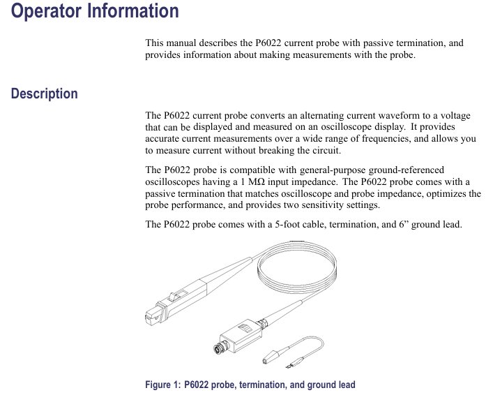
This document is the official manual for the Tektronix P6022 current probe (document number 070-0948-05). Its core function is to convert the AC current waveform into a voltage signal that can be measured by an oscilloscope, enabling current measurement without disconnecting the tested circuit. It is suitable for grounded general-purpose oscilloscopes with an input impedance of 1 M Ω and is mainly used in scenarios that require high-precision and wide frequency range current detection.
Core parameters of the product
1. Key electrical parameters (including guaranteed and typical characteristics)
Parameter Category Specific Indicator Remarks
Sensitivity options are available in two levels: 1 mA/mV and 10 mA/mV, controlled by the terminal sensitivity switch
Bandwidth (-3 dB) 1 mA/mV range: 8.5 kHz -100 MHz; 10 mA/mV range: 935 Hz-120 MHz requires an oscilloscope with a bandwidth ≥ 300 MHz
Intermediate frequency accuracy ± 3% calibration environment: 20 ° C-30 ° C (68 ° F-86 ° F)
Maximum current pulse current: 100 A peak (≤ 9 A · ms, if exceeded, the magnetic core will saturate); Continuous current: The reference frequency derating curve is 6 A p-p in the range of 3 kHz to 10 MHz at 10 mA/mV
Insertion impedance ≤ 0.03 Ω at 1 MHz and ≤ 0.2 Ω at 120 MHz affects high-frequency signal measurement, and attention should be paid to load effects
Rise time 1 mA/mV ≤ 3.2 ns; 10 mA/mV ≤ 2.9 ns reflects high-frequency response speed
Signal delay of about 9 ns with 5-foot probe cable and terminal
2. Environmental and mechanical parameters
Specific indicators for parameter categories
Working temperature: 0 ° C-50 ° C (32 ° F-122 ° F); Non working temperature: -40 ° C -65 ° C (-40 ° F -149 ° F)
Working altitude 2000 m (6561 ft); Non working altitude: 15240 m (50000 ft)
Cable length 5 feet (1.5 meters)
Weight probe+cable: 2.5 oz (≈ 71 g); Terminal: 1.7 oz (≈ 48 g)
The maximum wire diameter of 0.11 inches (2.79 mm) exceeding the specification will damage the probe clamp

Safety operation standards
1. General safety warning
Maintenance restrictions: Only qualified personnel are allowed to carry out repairs, avoiding separate operations. Before repairing, the power must be disconnected and refer to the safety summary.
Connection taboos: Do not plug or unplug probes/test wires with power on; The connection sequence is "connect the terminal to the oscilloscope first, then connect the probe to the circuit", and the disconnection sequence is reversed; The common terminal of the probe can only be grounded, and it is prohibited to connect to voltages higher than the ground potential.
Usage environment: Do not open the lid or use in damp/explosive environments; When measuring with bare wires, the voltage should not exceed 30 Vrms, 42 Vpk, or 60 VDC. Insulated wires are required above this voltage.
2. Probe operation safety
Sliding operation: When opening the sliding block, it should be held, and after placing the wire, it should be closed and locked (pushed to the transformer end about 1/8 inch) to ensure good contact between the two halves of the transformer.
Terminal protection: When measuring high currents, it is forbidden to disconnect the probe from the terminal (otherwise the secondary of the transformer will generate high voltage, causing electric shock or equipment damage).
Installation and usage guide
1. Installation steps
Terminal connection: Connect the BNC female head of the terminal to the probe output cable, and connect the BNC male head to the BNC input interface of the oscilloscope.
High frequency grounding: When measuring signals of ≥ 2 MHz, attach a 6-inch grounding wire to the probe transformer column and clamp it to RF ground to reduce interference and ringing.
Probe clamping: Open the slider → Place the measured wire into the transformer core (arrow direction is consistent with current direction, ensure correct waveform direction) → Close and lock the slider.
2. Usage skills
Reduce load effect: Prioritize clamping the probe at the low potential or ground terminal of the component to reduce its impact on the tested circuit.
Improve sensitivity: Increase the number of turns of the wire around the probe (e.g. 2 turns), doubling the sensitivity (e.g. 10 mA/division → 5 mA/division), but note that impedance increases with the square of the turns, which may affect high-frequency signals.
Anti magnetic field interference: In a strong magnetic field environment, use two probes to connect the positive and negative inputs of the oscilloscope, one clip the tested wire and one empty clip, and set the oscilloscope to "subtraction mode" to cancel out interference.
Performance validation and calibration
1. Required equipment
Equipment name, specification requirements, recommended model
Oscilloscope bandwidth ≥ 300 MHz, vertical sensitivity ≥ 1 mV/div, supports average amplitude TDS 303X, TDS 305X
Calibration generator fast edge (≤ 1 ns), sine wave (5 V) p-p@50 Ω, 935 Hz-120 MHz) Wavetek 9100, Tektronix PG 506A
Digital multimeter (DMM) AC voltage range, with an accuracy of 5.5 digits or higher, and an error of ≤ 0.5% at 50 kHz. Keithley 2000, HP 3458A
- ABB
- General Electric
- EMERSON
- Honeywell
- HIMA
- ALSTOM
- Rolls-Royce
- MOTOROLA
- Rockwell
- Siemens
- Woodward
- YOKOGAWA
- FOXBORO
- KOLLMORGEN
- MOOG
- KB
- YAMAHA
- BENDER
- TEKTRONIX
- Westinghouse
- AMAT
- AB
- XYCOM
- Yaskawa
- B&R
- Schneider
- Kongsberg
- NI
- WATLOW
- ProSoft
- SEW
- ADVANCED
- Reliance
- TRICONEX
- METSO
- MAN
- Advantest
- STUDER
- KONGSBERG
- DANAHER MOTION
- Bently
- Galil
- EATON
- MOLEX
- Triconex
- DEIF
- B&W
- ZYGO
- Aerotech
- DANFOSS
- Beijer
- Moxa
- Rexroth
- Johnson
- WAGO
- TOSHIBA
- BMCM
- SMC
- HITACHI
- HIRSCHMANN
- Application field
- XP POWER
- CTI
- TRICON
- STOBER
- Thinklogical
- Horner Automation
- Meggitt
- Fanuc
- Baldor


