
WAGO Rail-Mount Terminal Blocks
Installation method: Mainstream compatible with 35mm DIN rail, some support 15mm DIN rail or panel screw/buckle installation.
Suitable conductors: Copper and aluminum conductors (aluminum conductors need to be coated with "Alu Plus" contact paste to remove the oxide layer), with a cross-sectional range of 0.08-35mm ² (28-2 AWG).
General technical characteristics:
Connection technology: CAGE CLAMP ® Cage spring crimping (requires tools) Push-in CAGE CLAMP ® Direct insertion (tool free, compatible with solid/multi stranded conductors with cold pressed ends).
Electrical parameters: rated voltage 400V-1000V, rated current 6A-125A, pollution level 2-3, rated surge voltage 4kV-8kV.
Material safety: The insulation material is PA66/PPA/PC, the flame retardant grade is UL94 V0, the contact material is electrolytic copper+tin plating, and the spring is austenitic chromium nickel steel (corrosion-resistant and fatigue resistant).
WAGO Rail-Mount Terminal Blocks
Product Core Basic Information
1. Core positioning and applicable scenarios
Application areas: industrial control, electrical equipment wiring, lighting systems, motor wiring, marine equipment, explosion-proof scenarios (some models), etc.
Installation method: Mainstream compatible with 35mm DIN rail, some support 15mm DIN rail or panel screw/buckle installation.
Suitable conductors: Copper and aluminum conductors (aluminum conductors need to be coated with "Alu Plus" contact paste to remove the oxide layer), with a cross-sectional range of 0.08-35mm ² (28-2 AWG).
General technical characteristics:
Connection technology: CAGE CLAMP ® Cage spring crimping (requires tools) Push-in CAGE CLAMP ® Direct insertion (tool free, compatible with solid/multi stranded conductors with cold pressed ends).
Electrical parameters: rated voltage 400V-1000V, rated current 6A-125A, pollution level 2-3, rated surge voltage 4kV-8kV.
Material safety: The insulation material is PA66/PPA/PC, the flame retardant grade is UL94 V0, the contact material is electrolytic copper+tin plating, and the spring is austenitic chromium nickel steel (corrosion-resistant and fatigue resistant).
2. Compliance and Certification
International standards: comply with IEC/EN 60947, UL 1059, CSA C22.2 and other standards.
Special certification: Some models have passed ATEX (Ex i Explosion proof), DNV (Marine Equipment), LR (Classification Society) certifications, meeting the requirements for use in hazardous environments and marine scenarios.
Detailed analysis of core product series
1. Classic rail mounted terminal block (279/280/281/282/283/284/285 series)
Series positioning: The main series of industrial cabling, covering all scenario requirements from ordinary signals to power circuits.
Key parameters and characteristics of each series:
Series conductor cross-sectional range, core type, key characteristics, electrical specifications (typical), application scenarios
279 series 0.08-1.5mm ² straight/grounded/shielded/double-layer terminal block 2-4 conductor design, compact size, supports Ex i explosion-proof rated voltage 800V, rated current 18A signal circuit, control wiring
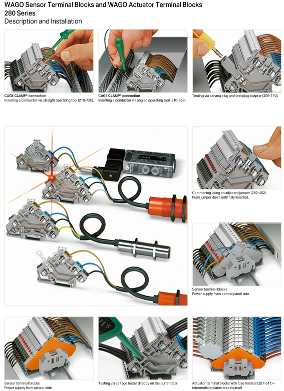
280 series 0.08-2.5mm ² straight through/grounded/shielded/double-layer/three-layer terminal block with multiple colors to choose from, with test slots, compatible with sensor/actuator wiring rated voltage 800V, rated current 24A industrial control, lighting system
281 series 0.08-4mm ² through/ground/fuse/isolation switch terminal block with rotatable fuse holder, some with LED fuse indication rated voltage 800V, rated current 10-26A, control circuit requiring overload protection
282 series 0.2-6mm ² isolation switch/test/fuse terminal block supports online testing, with locking function, anti misoperation rated voltage 630V, rated current 41A industrial equipment maintenance circuit, power branch
283 series 0.2-16mm ² high current through/ground terminal block compatible with medium power power circuits, supporting step-down jumpers, common potential rated voltage 800V, rated current 76A, motor control, power distribution
284 series 0.2-10mm ² high current through/fuse terminal block with fuse holder, supporting 35mm ² conductor distribution rated voltage 800V, rated current 57A, power circuit overload protection
285 series 6-35mm ² ultra-high current terminal block is suitable for heavy-duty power circuits, with copper bars connected to industrial power supply main lines and high-power equipment with a rated voltage of 1000V and a rated current of 125A
Detailed explanation of special types:
Fused terminal block: compatible with glass fuses of 5x20/25/30mm, 1/4 "x1" and other specifications. Some models come with LED or neon light fuse indication and support quick replacement of fuses (one end automatically pops out when the cover is opened).
Double/triple layer terminal block: The upper and lower layers are designed to be independent or have a common potential, saving rail space and adapting to motor L1/L2/L3/GND multi potential wiring.
Isolation switch terminal block: equipped with sliding isolation switch, supporting circuit power-off maintenance, and some with locking function to prevent accidental closing.
2. Pluggable connector terminal block (X-COM) ®- SYSTEM, 769/870 series)
Series positioning: For scenarios that require frequent maintenance and quick plugging, supporting modular combination.
Core product type:
Carrier terminal block (769 series): 1-4 pole design, including through/isolation switch/diode/LED types, compatible with 0.08-4mm ² conductors, rated current 16-32A, supports coding error prevention (16 coding combinations).
Double layer carrier terminal block (870 series): 2-4 pole double-layer design, supports L/N/GND multi potential distribution, compatible with 0.08-2.5mm ² conductors, rated current 16A.
Supporting plug: 1-15 pole straight/curved plug, with strain relief board, locking lever, protective cable pulling, supporting multiple plugs with common potential.
Core advantage: The plug and terminal block can be quickly separated, and there is no need to disconnect the wires during maintenance; Encode the key to prevent accidental insertion and improve wiring accuracy.
3. Matrix wiring system (726/727 series)
Series positioning: 19 inch rack specific, suitable for complex signal cross connection and centralized wiring of multiple devices.
Product type and characteristics:
Matrix terminal block (726 series): 32-80 pole design, supporting vertical identification, with common potential distribution module, compatible with 0.08-16mm ² conductors, rated current 10-76A.
Multilayer matrix terminal strip (727 series): 4-8 layer design, the same module supports independent connection of multiple groups of signals, adapts to 0.08-1.5mm ² conductors, and rated current is 12-18A.
Application scenarios: centralized wiring in data centers, industrial control cabinets, and signal distribution for large equipment.
4. Micro rail mounted terminal block (260/261/262/264 series)
Series positioning: Specialized for small spaces, such as internal wiring of small equipment and instruments.
Key features of each series:
260 series (0.08-1.5mm ²): 2-4 conductor design, supports panel installation, rated voltage 400V, rated current 18A.
261 series (0.08-2.5mm ²): with press on wiring, compatible with solid conductor direct insertion, rated voltage 500V, rated current 24A.
262 series (0.08-4mm ²): High current micro terminals, supporting power branching, rated voltage 630V, rated current 24A.
264 series (0.08-2.5mm ²): compatible with DIN-15/35 rails, with quick installation feet, rated voltage 800V, rated current 24A.
Core advantages: With a width of only 5-10mm, it saves installation space and supports Mini WSB micro marking system.
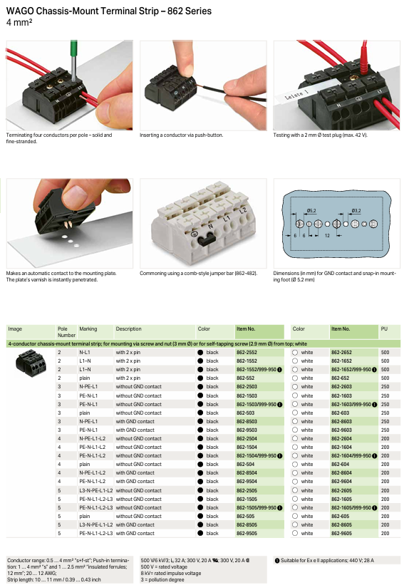
5. Panel installation terminal block (862/294 series)
Series positioning: Dedicated for equipment panels and enclosures, directly fixed to the panel rather than the guide rail.
862 series:
Conductor cross-section: 0.5-4mm ², 4-5 pole design, supports screw/snap fit installation, with grounding contact option.
Features: Automatic penetration of panel paint surface for grounding, supports 4 conductors/poles, adapts to internal wiring of equipment, rated voltage 500V, rated current 32A.
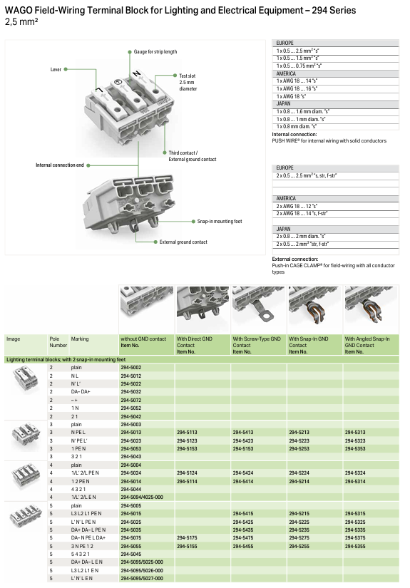
294 series (for lighting/electrical equipment):
Conductor cross-section: 0.5-2.5mm ², 2-5 pole design, supports PUSH WIRE ® Direct insertion technology.
Regional adaptation: Compliant with wiring standards of the European Union, the United States, and Japan, with multiple grounding methods (direct connection/screw/buckle), rated voltage of 500V, and rated current of 24A.
Application scenarios: wiring of lighting fixtures, household appliances, and building electrical wiring.
Special analysis of functional terminal block
1. Fused terminal block (281/282/284/811 series)
Core function: Integrated overload/short circuit protection, no additional fuse holder required.
Key specifications:
Fuse adaptation: 5x20/25/30mm glass fuse, 1/4 "x1" cartridge fuse, automotive plug-in fuse.
Indication method: Some models are equipped with LED (24V/120V/230V) or neon light fuse indication to quickly locate the faulty circuit.
Special model: 811 series suitable for photovoltaic scenarios, rated voltage 1000VDC, rated current 32A, supports 1-3 pole design.
2. Sensor/actuator terminal block (derived from 280 series)
Specially designed for sensor (PNP/NPN) and actuator wiring, with power distribution function.
Features:
Supports positive and negative pole distribution of power supply, with LED power indicator, low power consumption (4.8mA).
Partially equipped with shielded connections and grounding terminals, resistant to electromagnetic interference, suitable for industrial site wiring.
Wiring method: CAGE CLAMP ® Crimp connection, supports 0.08-2.5mm ² conductors, rated current 15-20A.
Key accessories and auxiliary products
1. Connection and common potential accessories
Jumper type:
Adjacent jumper: Suitable for terminal blocks of the same series with common potential, 2-12 poles optional, rated current 16-63A.
Interlocking jumper: supports non adjacent terminal blocks sharing the same potential, meeting the requirements of complex circuit design.
Voltage reducing jumper: Achieve common potential for different cross-sectional terminal blocks (such as 35mm ² and 4mm ²), such as 283-414 (16mm ² to 4mm ²).
Push in jumper: Insulated design, plug and play, rated current 30A.
2. Identification and protective accessories
Identification system:
WMB series: compatible with smart printers, packaged in 1500 pieces, can stretch 5-5.2mm, available in multiple colors (yellow/gray/green/purple, etc.).
Mini WSB series: Miniature markers, compatible with miniature terminal blocks, supporting snap on installation.
Protective accessories:
Finger protection cover: Seal unused conductor entrances to prevent electric shock.
Insulation blocking: isolates adjacent terminals, prevents short circuits, and is compatible with double-layer/three-layer terminal blocks.
Warning sign: Insert into the operating slot to indicate high voltage/hazardous circuits.
3. Testing and installing accessories
Test accessories:
Test plug: 6mm/4mm wide, compatible with test slot, rated current of 24A, supports live testing.
Test plug adapter: 5mm wide, compatible with different terminal block test interfaces.
Installation accessories:
End plate/middle plate: 2-4mm thick, used for end sealing of terminal block groups to enhance mechanical stability.
DIN rail: 210 series, 35x7.5/15mm specification, steel/copper material, galvanized treatment, corrosion-resistant.
Snap on mounting feet: 209-123 series, suitable for panel installation, with a spacing of 35-40mm.
Installation and wiring operation specifications
1. Key requirements for wiring
Conductor processing:
Stripping length: 8-23mm (depending on the series, such as micro terminal block 8-9mm, high current terminal block 16-23mm).
Multi strand conductor: Cold pressed terminals (216 series) are required, otherwise one size larger terminal block should be selected.
Aluminum conductor: After cleaning the surface oxide layer, apply "Alu Plus" contact paste to prevent oxidation and electrolytic corrosion.
Wiring steps:
CAGE CLAMP ®: Insert the tool into the rectangular opening → Open the fixture → Insert the conductor → Pull out the tool lock.
Push-in CAGE CLAMP ®: Solid/multi stranded conductors with ends inserted directly; Other conductors need to be inserted with tools tilted into the opening and unlocked before insertion.
2. Installation precautions
Spacing requirement: Reserve 20mm on both sides of the terminal block group, and reserve 35-65mm above and below to ensure heat dissipation.
Grounding requirements: In hazardous voltage scenarios, DIN rails must be grounded (PE) to ensure electrical safety.
Explosion proof scenario: Select Ex i certified models and reserve creepage distance as required (e.g. 4 distance modules need to be connected after Ex i module).
Typical application scenarios and configuration schemes
1. Industrial control circuit
Configuration: 280 series straight through terminal block+281 series fused terminal block+769 series pluggable terminal block.
Advantages: Control circuit overload protection, quick insertion and removal during maintenance, signal and power partition wiring.
2. Motor wiring
Configuration: 283 series high current terminal block+281 series double-layer terminal block+grounding terminal block (green and yellow).
Advantages: L1/L2/L3/GND multi potential distribution, saving rail space, and adapting to motor power and control circuits.
3. Wiring of marine equipment
Configuration: 282 series isolation switch terminal block+726 series matrix terminal block+DNV certified end board.
Advantages: Resistant to salt spray corrosion, supports circuit isolation maintenance, and meets marine compliance requirements.
4. Explosion proof scenario wiring
Configuration: 279/280 series Ex i certified terminal block+distance module (750-616)+explosion-proof fuse.
Advantages: Meets ATEX certification, prevents electric sparks from igniting hazardous gases, and is suitable for Zone 2/22 hazardous areas.
Summary of Product Core Advantages
Modular design: supports free combination, universal terminal blocks and accessories, reducing inventory costs.
Efficient wiring: Push in technology requires no tools, CAGE CLAMP ® Reliable crimping, anti vibration, maintenance free.
Full coverage of scenarios: from signals to power, from ordinary to explosion-proof/marine scenarios, suitable for all industrial needs.
Safety compliance: Through multiple international certifications, complete protective measures (anti electric shock, anti misoperation, anti short circuit).
- OMRON
- ABB
- General Electric
- EMERSON
- Honeywell
- HIMA
- ALSTOM
- Rolls-Royce
- MOTOROLA
- Rockwell
- Siemens
- Woodward
- YOKOGAWA
- FOXBORO
- KOLLMORGEN
- MOOG
- KB
- YAMAHA
- BENDER
- TEKTRONIX
- Westinghouse
- AMAT
- AB
- XYCOM
- Yaskawa
- B&R
- Schneider
- KONGSBERG
- NI
- WATLOW
- ProSoft
- SEW
- ADVANCED
- Reliance
- TRICONEX
- METSO
- MAN
- Advantest
- STUDER
- DANAHER MOTION
- Bently
- Galil
- EATON
- MOLEX
- DEIF
- B&W
- ZYGO
- Aerotech
- DANFOSS
- Beijer
- Moxa
- Rexroth
- Johnson
- WAGO
- TOSHIBA
- BMCM
- SMC
- HITACHI
- HIRSCHMANN
- Application field
- XP POWER
- CTI
- TRICON
- STOBER
- Thinklogical
- Horner Automation
- Meggitt
- Fanuc
- Baldor
- SHINKAWA
- Other Brands
- UniOP
- KUKA
- Iba
- Beckhoff
-
 Basler DECS-200-2L Digital Excitation Control
 -
 Basler BE1-47N Voltage Phase Sequence Relay
 -
 Basler AEC63-7 Analog Excitation Controller 220-277V
 -
 Basler BE1-50/51B-107 Overcurrent Relay
 -
 Basler Electric BE1‑32R BE1‑E1P‑BON0F Protective Relay
 -
 Basler BE1-25 Solid State Time Overcurrent Relay M1EA6PA5S1F
 -
 Basler MVC 232 Manual Voltage Control Module 90 37000 103 60VAC 55VDC
 -
 Basler RAL6144-16GM Racer GigE Line Scan Camera
 -
 Basler SSR 63-12 Static Voltage Regulator
 -
 Basler BE1-51A Overcurrent Relay
 -
 Basler BE1-87T Solid State Protective Relay
 -
 Basler SR4A2B01B3A Static Voltage Regulator
 -
 Basler SSR 32-12 Static Voltage Regulator
 -
 Basler TRR00696 Transformer 1KVA 115V
 -
 Basler DECS-100-B15 AVR Replacement
 -
Basler BE1-27 Under-Voltage Relay
-
 Basler ACA2000-50GM Interface Module
 -
 Basler AEC63-7 Analog Excitation Controller
 -
 Basler PRS 250 Veri-Sync Relay
 -
 Basler SR4A-2B15B3A Static Voltage Regulator
 -
Basler BE1-32R Power Relay
-
Basler SR8A-2B06B3E Static Voltage Regulator
-
Basler BE1-81 O/U Frequency Relay
-
 Basler BE1-51A-K2E-W6M-B1N0F Overcurrent Relay
 -
Basler BE1-851 Overcurrent Relay G3A1S1 – 48-125V AC/DC
-
 Basler BEI-51 Overcurrent Relay – NSN 5945-01-293-2363
 -
Basler Electric L301KC Protective Relay – L301KC
-
 Basler DECS-100-B15 Automatic Voltage Regulator – Generator AVR
 -
 Basler SR4A-2B15B3A Static Voltage Regulator – SR4A2B15B3A
 -
 Basler UF 312 Under Frequency Protective Module – 9094700100
 -
Basler Electric MVC 232 Manual Control Module – 60VAC 55VDC 20A
-
Basler PRS 250 Veri-Sync Relay – Generator Synchronizing Relay
-
 Basler DECS-100-A05 Digital Regulator Review
 -
 Basler AEM-2020 Analog Expansion Module Specs
 -
 Basler DECS-100-B15 Digital Excitation Specs
 -
Basler Electric 9125600106 Regulator Component
-
Basler BE1-51A-K1E-W6M-B1N0F Overcurrent Relay
-
 Basler MVC-301 MVC 300 Excitation Controller
 -
 Basler SSR 32-12 Static Voltage Regulator
 -
 Basler 9-2849-00-101 Control Module
 -
Basler BE1-51A Overcurrent Relay
-
 Basler BE1-51/27R Overcurrent Relay
 -
 Basler BE1-51 Overcurrent Relay
 -
 Basler SR8A-2B15B3A Static Voltage Regulator
 -
 Basler BE32965001 Transformer and Timer Board
 -
 Basler 9174700100 EL200-7 Excitation Limiter
 -
 Basler BE2000E AVR Voltage Regulator
 -
Basler BE1-87G Differential Relay
-
 Basler BE21834001 Generator Control Module
 -
Basler DECS-100-B15 AVR
-
 Basler D90 96801 100 PCB Card
 -
 Basler XR2002F Voltage Regulator (110 VAC, 48-480 Hz)
 -
 Basler SR8A-2B14B3A Regulator
 -
 Basler 9561500100 Module
 -
 Basler DECS-400 BE1-11 System
 -
 Basler DECS-100-B15 Excitation Control
 -
 Basler SCP 210 Frequency Controller
 -
Basler SR4A-2B15B3A Static Voltage Regulator
-
Basler BE1-32R Power Relay
-
 Basler PIA2400-17GM Power Interface Adapter
 -
 Basler MVC 232 Manual Voltage Control Module
 -
 Basler SSR 32-12 Static Voltage Regulator
 -
Basler 5MW AVR Generator Voltage Regulator
-
 Basler VR63-4B Voltage Regulator
 -
Basler DECS-100-A05 AVR for Engine Generator
-
Basler DECS-100-B15 Automatic Voltage Regulator
-
Basler BE1-32R Directional Power Relay
-
Basler BE1-87B Differential Relay
-
 Basler UFOV 260A Protective Module
 -
 Basler 9-2614-02-100 PCB Rev M
 -
Basler DECS-100-B15 Digital AVR
-
 Basler 9284900103 PS DECS-400N
 -
 Basler D4N3H1U Intertie Protection
 -
 Basler DECS-100-B15 A15 AVR
 -
 Basler KR4F Voltage Regulator
 -
 Basler BE26434 T14 Transformer
 -
 Basler SR8A-2B15B3A Regulator
 -
 Westinghouse 774B472A12 AR Relay
 -
Basler DECS-100-B15 AVR
-
Basler XR2002F Regulator 110V
-
Basler SR125-E Static Regulator
-
Basler SSR 125-12 Regulator
-
Basler MOC2599 Motor Pot
-
 Basler BE1-DFPR Feeder Relay
 -
 Basler CBS 305 Current Boost
 -
Basler BE1-25 AutoSync
-
Basler MVC 300 Voltage Control
-
 Basler BE3-25A AutoSync
 -
 Basler KR7FF Static Regulator
 -
Basler 90-49000-100 Regulator
-
 Basler 880 kVA Dry Type Transformer Specs
 -
Basler Electric BE1-25 Sync-Check Relay Specs
-
 Basler SSR 125-12 Voltage Regulator Specs
 -
 Basler Electric BE1-851 Overcurrent Relay Review
 -
Basler Electric 149D930G02 Control Sub-Assembly
-
 Basler Electric BE1-81O/UT Frequency Relay Specs
 -
 Basler Electric BE1-51/27C Overcurrent Relay
 -
 Basler Electric 149D956G02 Industrial Component
 -
Basler Electric BE1-51A Overcurrent Relay Specs
-
 Basler Electric BE1-40Q Loss of Excitation Relay
 -
Basler DECS-200 Excitation Control System
-
 Basler DECS-200 Voltage Regulator 56-277V AC / 125V DC
 -
Basler BE1-87T Transformer Differential Relay
-
 Basler RDP-110-S1 Protection Relay
 -
 Basler BE1-700V Digital Protective Relay
 -
 Basler BE1-951 Overcurrent Protection System
 -
 Basler DECS-300 Digital Excitation Control
 -
 Basler DECS-200 Digital Excitation Control
 -
 Basler DECS-200-1C Excitation Control System
 -
Basler DECS-200-1L Digital Excitation Control
-
 Basler Electric BE1-GPS Generator Protection System
 -
Basler Electric DECS-200-1C Digital Excitation Controller
-
 Basler Electric DECS125-15 Excitation Control with Power Module
 -
Basler Electric BE1-87G Differential Relay
-
 Basler Electric BE1-11 Protection System I5A3M2P2N0EA00
 -
Basler Electric DECS-200-1C Excitation Control System
-
Basler Electric BE1-11g Generator Protection Relay
-
Basler Electric DECS 125-15-B2C1 V2.0.9 Excitation Control
-
Basler Electric BE1-81O/UT3ED1JA7N2F Frequency Relay
-
Basler Electric BE1-81O/UT3EE1YB7N1F Frequency Relay
-
 Basler Electric DECS-200-1L Digital Excitation Control System
 -
Basler DECS125-15-B2C1 Excitation Control
-
 Basler 9507900205 SSR Retrofit Voltage Regulator
 -
 Basler BE2000E Digital Voltage Regulator
 -
 Basler BE1-GPS Generator Protection System
 -
Basler DECS-250-CN1CN1N Digital Excitation Control
-
 Basler DGC-2020 Genset Controller
 -
Basler BE1-81O UT3ED1LA7N0F Frequency Relay (Variant)


