
YOKOGAWA SC4AJ Conductivity Sensor Manual
YOKOGAWA SC4AJ Conductivity Sensor Manual
Equipment foundation and adaptation system
1. Core positioning and application scenarios
SC4AJ is a compact sensor designed specifically for low conductivity solutions, suitable for industries such as semiconductors, power, and pharmaceuticals that require high purity (such as ultrapure water detection). It needs to be paired with a specific analyzer/converter to form a complete detection system. The compatible equipment and corresponding manual information are as follows:
Corresponding manual number for supporting equipment type
FLXA202, FLXA21 2-wire analyzer IM 12A01A02-01E
FLXA402 4-wire converter IM 12A01F01-02EN, IM 12A01F03-01EN, etc
SC450G Conductivity Converter IM 12D08N05-01E
SA11 Smart Adapter IM 12A06S01-00EN-P
2. Equipment core classification and parameters
SC4AJ is classified into models based on electrode material, installation method, and battery constant. The core differences focus on adaptation scenarios and measurement ranges. The specific classifications are as follows:
Classification dimensions, specific types, key parameters/characteristics
Electrode material titanium (- T) is only suitable for adapter installation type (- AD), with strong corrosion resistance
316L stainless steel material (- S) is compatible with all installation methods and has strong universality
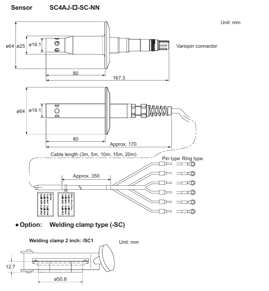
Installation method: Adapter installation type (- AD) with 3/4NPT or R3/4 adapter (stainless steel/PVDF material), sensor length 9cm/15cm
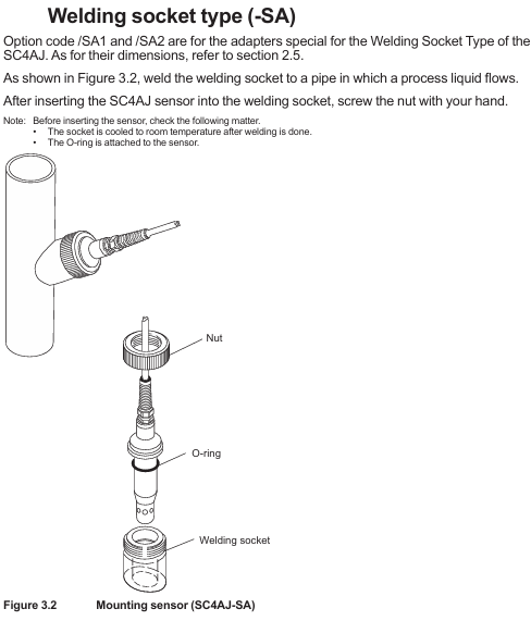
Welding socket type (- SA) requires straight type (/SA1) or 15 ° angle type (/SA2) welding socket, with fixed sensor length
Welding clip type (- SB/- SC) - SB compatible 1/1.5 inch clip (/SB1//SB2), - SC compatible 2-inch clip (/SC1), including sealing ring
Battery constant 0.02 cm ⁻¹ (-002) measurement range 0-0.5 μ S/cm to 0-200 μ S/cm, suitable for extremely low conductivity solutions
0.1 cm ⁻¹ (-010) measurement range 0-5 μ S/cm to 1 mS/cm, suitable for low conductivity solutions
Cable terminal pin type/M4 ring type/M3 ring type/Variopin pin type compatible with multiple devices; M4 ring adapter FLXA202/FLXA21; M3 ring adapter FLXA402/SC450G; Variopin compatible with SA11
3. General technical specifications
Temperature and pressure: The electrode has a conventional temperature of 0-110 ℃ (can be steam sterilized at 135 ℃ for 30 minutes) and a pressure of 0-1 MPa; The tolerance range of the bracket varies with the material (stainless steel 316L has higher temperature resistance, PVDF has lower temperature resistance, please refer to the temperature pressure curve for details)
Contact fluid material: main body (316L stainless steel/titanium), O-ring (FKM fluororubber, EPDM EPDM EPDM), adapter (PVDF or 316L stainless steel)
Temperature compensation: Built in Pt1000 temperature sensor to calibrate the effect of temperature on conductivity
Protection restriction: The sensor mold and metal joint are not waterproof and cannot be immersed in process water

Safety regulations and usage restrictions
1. Core security principles
Prohibited unauthorized operation: Only use according to the instructions in the manual, unauthorized modification of the device will result in loss of protective function; Repairs require Yokogawa certified spare parts, unauthorized modifications are prohibited
Static electricity and explosion prevention: The flow of ultrapure water in plastic pipes may generate static electricity, and it is necessary to avoid the sensor conducting static electricity and damaging the converter circuit; Must comply with explosion-proof standards such as IEC 60079-11 and GB 3836.4-2010 (TIIS certified models cannot be connected), and if necessary, affix a "simple equipment" label
Temperature limit: The maximum process temperature needs to be determined based on the supporting analyzer (FLXA202/FLXA21) and temperature level (T1-T6). For example, under T6 level, the maximum process temperature at 40 ℃/60 ℃ ambient temperature is 49 ℃; At T5 level, the ambient temperature is 95 ℃ at 40 ℃ (note that the upper limit of T5 level is 100 ℃)
2. Manual usage guidelines
It needs to be handed over to the end user and properly stored, and unauthorized copying/dissemination is prohibited; Yokogawa reserves the right to improve manuals and equipment without prior notice
The manual only describes the device functions and does not guarantee adaptation to specific user scenarios; The equipment is provided as is, and Yokogawa is not responsible for unforeseeable direct/indirect losses
Installation and Wiring Guide
1. Core installation requirements
Installation principle: Ensure uniform composition and no dead zone when the solution flows through the sensor; The sensor needs to be submerged above the outlet to ensure continuous liquid flow between the electrodes; Reserve maintenance space for easy disassembly and release of process pressure; Confirm that the pressure at the installation site is within the tolerance range of the sensor and adapter
Steps for different installation methods:
Adapter installation type (- AD): Assemble in the order of "nut → adapter support (stainless steel adapter) → adapter → sealing ring → sensor body", tighten the nut with a torque of about 190 N · m (tighten with fingers and then use a wrench to tighten 1.25 turns)
Welding socket type (- SA): First weld the welding socket to the process pipeline (cool to room temperature), insert the sensor into the socket after installing the O-ring, and fix it by hand tightening the nut
Welding clamp type (- SB/- SC): First weld the flange to the pipeline, insert the sensor into the flange after installing the sealing ring, and fix it with a special fixture
2. Wiring requirements
Wiring logic: Connect according to the cable end identification and the terminal number of the analyzer/converter, for example, connect the temperature sensor wire (brown/black/red) to the corresponding temperature terminal, and the electrode wire (green/yellow) to the corresponding electrode terminal; Variopin terminal (- VS) needs to be connected to SA11 adapter
Cable specifications: Cable length 3-20m (selected according to the order), avoid contact with high-temperature components, and ensure that the insulation resistance meets the requirements after wiring (such as 1000-1137 Ω between terminals 11-12 and>100 M Ω between terminals 11-13)
Operation and maintenance process
1. Preparation and calibration before operation
Pre operation inspection: Confirm that the cable connection is correct, the solution is leak free, the temperature/pressure is within the range, and the solution level reaches the outlet height
Battery constant setting: The factory calibrated battery constant on the cable label needs to be input into the matching analyzer/converter (refer to the corresponding equipment manual for operation steps)
Calibration requirements: Use a standard solution with known conductivity for calibration (the conductivity of the standard solution should be close to that of the test liquid). Before calibration, the sensor should be equilibrated with the temperature of the solution, and the temperature should be measured using a calibration thermometer
2. Core maintenance operations
(1) Sensor cleaning
Choose the cleaning method based on the type of pollutant, and prohibit mixing hydrochloric acid with chlorine containing solvents (to avoid producing toxic chlorine gas):
Scale and hydroxides: Clean with 5-10% hydrochloric acid solution
Organic dirt (oil, grease): Wipe with ethanol or acetone
Algae/bacteria: Clean with chlorine containing solution (household bleach)
Conventional pollution: cleaning with hot water and household detergent
After cleaning, visually inspect the sensor for any damage or deformation
(2) Abnormal judgment
After the sensor dries, measure the resistance between the terminals with a digital multimeter. If it exceeds the following range, it needs to be replaced:
Terminal combination (non VS) Variopin terminal combination (- VS) standard resistance at room temperature
11-12 E-F 1000-1137 Ω
11-13, 13-15, 12-15 E-C, C-A, F-A>100 M Ω
13-14, 15-16 C-D, A-B < 10 Ω
3. Spare parts information
Core spare parts need to be matched according to the installation method, and common spare parts are as follows:
Type description corresponding to spare part number
K9670MA SA (non VS) O-ring
K9670VY SA (- VS) O-ring set
K9670MK-SB sealing ring (compatible/SB1//SB2)
K9670MP SC sealing ring (compatible/SC1)
K9670MT/MU-AD 3/4NPT stainless steel/PVDF adapter
K9670ME/MD-SA straight/angle welding socket and installation nut
- OMRON
- ABB
- General Electric
- EMERSON
- Honeywell
- HIMA
- ALSTOM
- Rolls-Royce
- MOTOROLA
- Rockwell
- Siemens
- Woodward
- YOKOGAWA
- FOXBORO
- KOLLMORGEN
- MOOG
- KB
- YAMAHA
- BENDER
- TEKTRONIX
- Westinghouse
- AMAT
- AB
- XYCOM
- Yaskawa
- B&R
- Schneider
- KONGSBERG
- NI
- WATLOW
- ProSoft
- SEW
- ADVANCED
- Reliance
- TRICONEX
- METSO
- MAN
- Advantest
- STUDER
- DANAHER MOTION
- Bently
- Galil
- EATON
- MOLEX
- DEIF
- B&W
- ZYGO
- Aerotech
- DANFOSS
- Beijer
- Moxa
- Rexroth
- Johnson
- WAGO
- TOSHIBA
- BMCM
- SMC
- HITACHI
- HIRSCHMANN
- Application field
- XP POWER
- CTI
- TRICON
- STOBER
- Thinklogical
- Horner Automation
- Meggitt
- Fanuc
- Baldor
- SHINKAWA
- Other Brands
- UniOP
- KUKA
- Iba
- Beckhoff
-
 Basler KR7FFX Static Regulator 840V
 -
 Basler EL200-7 Voltage Regulator 90-660VAC 7A
 -
 Basler PRP210-1 Reverse Power Relay 9056300102
 -
 Basler SSR 63-12 Static Regulator 600VAC
 -
 Basler 9289901106 Digital Board
 -
Basler DECS100 Voltage Regulator DECS100A01
-
 Basler Electric CEM-2020 Contact Expansion Module
 -
 Basler Electric BE3-25-1 C1 N4 Synchronizing Check Relay
 -
 Basler Electric ACA2000-50GM GigE Camera 2MP 50fps
 -
 Basler Electric ACA2240-20GMSYM GigE Camera Sony IMX264
 -
 Basler BE1-50G Ground Overcurrent Relay
 -
 Basler PRS250 Veri-Sync Relay
 -
 Basler MOC2199 Output Module
 -
 Basler UFOV 260A Underfrequency Overvoltage Module
 -
 Basler BE-15482-001 Control Module
 -
 Basler LSP4-7 Protective Relay
 -
 Basler SCP 250-G-60 VAR Power Factor Controller
 -
 Basler BE146N Negative Sequence Overcurrent Relay
 -
Basler APR63-5 Automatic Voltage Regulator
-
Basler 9507900107 SR8A Retrofit Voltage Regulator
-
Basler BE1-320 Directional Power Relay
-
 Basler KR7F Voltage Regulator 9116200100
 -
Basler UFOV 260A Overvoltage Protective Module
-
 Basler AEC63-7 Analog Excitation Controller
 -
Basler 9992D90G01 Control Module
-
 Basler 6966D22G01 Control Board
 -
 Basler 6965D40G01 Control Board
 -
 Basler BE1-50/51M-104 Overcurrent Relay
 -
 Basler BE1-BPR Programmable Breaker Relay
 -
 BASLER Electric SSR 125-9 1256 00 102 Static Voltage Regulator
 -
 Basler Electric MVC 112 Manual Voltage Control
 -
 Basler Electric 9321000102 Control Module
 -
 Basler Electric RA-70-MDCT7 Rectifier Assembly
 -
 Basler Electric ACA1300-60GM GigE Camera
 -
 Basler Electric 6427C85G01 Interface Board
 -
Basler Electric 6965D05G01 Control Board
-
Basler Electric ACA2500-14UC Current Transducer
-
 Basler Electric 9170206111 Protective Relay
 -
 Basler Electric BE1-11-G6D1M1J1P0E000 Protection Relay
 -
Basler Electric BE1-50/51B-107 Overcurrent Relay
-
 Basler 9121000106 Voltage Controller
 -
 Basler B3E-E1P-A0N0F Solid State Protective Relay
 -
 Basler 9121000106 Manual Voltage Control
 -
Basler PRP320 Motor Pull-out Relay
-
 Basler SSE-N 250-9KW Shunt Exciter Regulator
 -
 Basler BE1-50-51B-107 Overcurrent Relay
 -
 BASLER ELECTRIC MVC 108 MANUAL VOLTAGE CONTROL MODULE 9 0370 00 102
 -
Basler BE1-59N-A7E-D1J-D0N0F Ground Overvoltage Relay
-
Basler BE1-46N-G1E-B8P-B0N0F Negative Sequence Overcurrent Relay
-
Basler BE1-951 Overcurrent Protection System
-
 Basler Electric MOC2199 Motor Operated Potentiometer
 -
 Basler Electric BE1-60 Voltage Balance Solid State Relay B1FA1C1M1F
 -
 Basler Electric BE1-67N Directional Overcurrent Relay
 -
Basler Electric PIA2400-17GM Interface Module
-
 Basler Electric V6RAB Rectifier Module
 -
Basler Electric BE1-32R Reverse Power Relay B2E E1R A0N1F
-
Basler Electric IFM-150 Firing Circuit Chassis 120V AC
-
 Basler Electric IFM-102 Firing Circuit Chassis 120V AC
 -
 Basler Electric 9170206111 NSNP Control Module
 -
Basler Electric SSR 63-12 Static Voltage Regulator
-
 Basler UFOV 260A Overvoltage Protective Module
 -
Basler SCA1300-32GM CCD Camera Lens Enclosure
-
 Basler BA1-27 Under Voltage Relay
 -
Basler 149D866G06 Control Board
-
 Basler 9072300130 Power Supply Module
 -
Basler CBS 305 Current Boost System
-
 Basler BE1-60 Voltage Balance Relay
 -
 Basler Electric CBS 212 Current Boost System Sensing 120/240VAC 50/60Hz 10VA
 -
 Basler MVC-300 Manual Voltage Control Unit
 -
Basler SSR125-12 Static Voltage Regulator 918500102
-
 Basler SR32A2B05B3E Static Voltage Regulator
 -
Basler Electric BE1-59N Ground Fault Overvoltage Relay
-
 Basler Electric 9110000113 Excitation Module
 -
Basler Electric 90-72300-114 Control Accessory
-
Basler Electric PRS-250 Protection Relay System
-
Basler Electric BE1-50/51M-109 Overcurrent Relay
-
 Basler Electric SR4A1B10B3E Static Voltage Regulator
 -
 Basler Electric CBS 212 Current Boost System
 -
Basler Electric SR32A2B05B3E Static Voltage Regulator
-
Basler Electric MOC2207 Motor Operated Potentiometer
-
 Basler Electric SR4A1B05A3E Static Voltage Regulator
 -
Basler Electric BE1-32R Power Relay B2EE1PA0N1F
-
Basler BEI-81 Underfrequency Relay
-
Basler CBS 212A Current Boost System
-
Basler SSR 63-12 Static Voltage Regulator
-
 Basler DGC-2020 Digital Genset Controller
 -
Basler BE1-32 Reverse Power Relay
-
 Basler BE1-50/51B-207 Overcurrent Relay
 -
Basler BE1-951 Overcurrent Protection System
-
 Basler 9073800-103 Power Supply
 -
Basler SCA1300-32FC CCD Camera
-
Basler 9073800-103 Power Supply
-
Basler SCA1300-32FC CCD Camera
-
 Basler L304KC Protective Relay
 -
 Basler BE3-25-1S1N4 Time Overcurrent Relay
 -
Basler 9032300113 Excitation Support System
-
Basler BE1-59N Ground Overvoltage Relay
-
Basler MVC-300 Manual Voltage Control Unit
-
Basler MOC2102 Potentiometer
-
 Basler BE1-87G Generator Differential Relay
 -
 Basler Electric DECS-200 Digital Excitation Control System
 -
Basler Electric DECS 125-15-B2C5 Digital Excitation System
-
 Basler Electric PLA2400-12GM Power Supply
 -
 Basler Electric BE1-50/51B-235 Overcurrent Relay
 -
Basler Electric BE1-27/59 Undervoltage Overvoltage Relay
-
Basler Electric CEM-2020 Contact Expansion Module
-
 Basler Electric BE1-32R Solid State Power Relay
 -
 Basler Electric BE1-700 Digital Generator Management Relay
 -
Basler Electric BE1-59N Ground Fault Overvoltage Relay
-
Basler Electric BE10493002 Protection Module
-
 Basler Electric BEI-79A1AA5CA3M1F Digital Annunciator
 -
 Basler Electric SSR 32-12 Static Voltage Regulator
 -
Basler Electric BE1-CDS240 Current Differential System
-
Basler Electric BE1-67 Directional Overcurrent Relay
-
 Basler Electric 9121000106 DECS-100 Voltage Controller
 -
Basler Electric BEI-871 Interface Module
-
Basler Electric 8650C72 Exciter Control Module
-
Basler Electric RDP-110-S1 Generator Annunciator
-
Basler Electric BE1-32O/U Directional Power Relay
-
 Basler Electric BE2000E AVR Voltage Regulator
 -
BASLER ELECTRIC BE1-50F2EA1PA0N0F Instantaneous Overcurrent Relay
-
BASLER ELECTRIC BE1-81T1EE1WA0N1F Underfrequency Relay
-
Basler BE1-67 Directional Overcurrent Relay
-
Basler BE1-25/79TR Reclosing Relay
-
Basler CEM-2020 Contact Expansion Module
-
Basler BE1-11 Overcurrent Protection Relay
-
 Basler BE1-GPS Generator Protective Relay
 -
 BASLER ELECTRIC MVC-300 MANUAL VOLTAGE CONTROL UNIT 9121000106


