
YASKAWA SGMCS series direct drive servo motor
YASKAWA SGMCS series direct drive servo motor
Core positioning
The YASKAWA SGMCS series directly drives servo motors and SGDS/SGDH series servo amplifiers, providing full process guidance for high-precision industrial equipment design. The core focus is on the three major advantages of high torque, high precision, and no backlash of gearless direct drive technology, covering product lineup, technical parameters, system configuration, wiring specifications, peripheral equipment selection, and order reference in detail. It is suitable for high-precision application scenarios such as semiconductor manufacturing, LCD panel production, electronic component assembly, and IC testing, helping engineers achieve equipment miniaturization, high performance, and low maintenance design.
Product System and Model Interpretation
(1) Servo motor (SGMCS series)
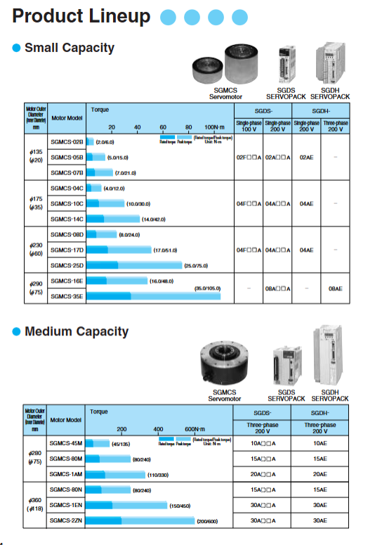
1. Product classification and core specifications
Capacity level, outer diameter specification (mm), model series, rated torque (N · m), peak torque (N · m), rated speed (min ⁻¹), maximum speed (min ⁻¹), rotor moment of inertia (kg · m ² × 10 ⁴)
Small Capacity 135 (Type B) 02B/05B/07B 2.0/5.0/7.0 6.0/15.0/21.0 200 500 28/51/77
175 (Type C) 04C/10C/14C 4.0/10.0/14.0 12.0/30.0/42.0 200-300 300-500 77/140/220
230 (D-type) 08D/17D/25D 8.0/17.0/25.0 24.0/51.0/75.0 150-200 250-500 285/510/750
290 (Type E) 16E/35E 16.0/35.0 48.0/105.0 150-200 250-500 930/1430
Medium capacity 280 (M-type) 45M/80M/1AM 45.0/80.0/110.0 135.0/240.0/330.0 150 300 388/627/865
360 (N-type) 80N/1EN/2ZN 80.0/150.0/200.0 240.0/450.0/600.0 150 250-300 1360/2470/3060
2. Model coding rules (taking SGMCS-04C3C11 as an example)
SGMCS: Identification of Direct Drive Servo Motor Series
04: Rated torque 4N · m
C: Motor outer diameter specifications (B=135mm, C=175mm, D=230mm, E=290mm, M=280mm, N=360mm)
3: Encoder type (3=20 bit absolute type (standard), D=20 bit incremental type (optional))
C: Installation flange specifications (1=no brake+drive end C-face, 3=no brake+non drive end C-face, 4=no brake+side outlet)
11: Design version number
3. Key characteristics
Accuracy configuration: 20 bit absolute encoder (standard), resolution 1048576 P/R, absolute accuracy ± 15 seconds, repeat positioning accuracy ± 1.3 seconds
Structural design: Fully enclosed self cooling (IP protection level), hollow shaft structure (compatible with wiring/piping), lightweight aluminum alloy shell
Environmental adaptation: working temperature 0-40 ℃, storage temperature -20-70 ℃, relative humidity 20% -80% (no condensation), vibration level V15
Electrical characteristics: Insulation level A (small capacity)/F (medium capacity), insulation resistance ≥ 10M Ω (500VDC), withstand voltage 1500VAC/1 minute
(2) Servo amplifier (SGDS/SGDH series)
1. Product classification and adaptation scope
Amplifier series power supply specifications, motor capacity, continuous output current (Arms), maximum output current (Arms), control mode, core functions
SGDS single-phase 100VAC small capacity (B/C/D type) 2.1-2.8 6.5-8.5 position/speed/torque control electronic gear, encoder frequency division, basic I/O control
Single phase 200VAC small capacity (B/C/D/E type) 2.1-11.6 6.5-28.0 Position/Speed/Torque Control Electronic Gear, Regenerative Resistance Connection, Fault Alarm
SGDH single-phase/three-phase 200VAC full capacity (B/C/D/E/M/N type) 2.1-24.8 6.2-56.0 position/speed/torque control (extended function) self-tuning, harmonic suppression, RS422 communication
2. Model coding rules (taking SGDS-02A01A as an example)
SGDS/SGDH: Identification of servo amplifier series (SGDH supports extended functions)
02: Maximum adaptive motor capacity (02=0.2kW, 04=0.4kW, 08=0.75kW, etc.)
A/F: Supply voltage (A=200VAC, F=100VAC)
01: Interface Specification (01=Standard Type: Analog Voltage/Pulse Reference)
A: Design version number
Core technical parameters and performance advantages
(1) Key performance indicators
Performance category specific parameter notes
Torque characteristics Rated torque: 2-200N · m; Peak torque: 6-600N · m Medium capacity models support long-term constant torque output
Speed characteristics Rated speed: 150-200min ⁻¹; Maximum speed: 250-500min ⁻¹ Low speed and high torque characteristics, no reduction mechanism required
Absolute positioning accuracy ± 15 seconds, repeated positioning accuracy ± 1.3 seconds, no gear backlash, and a 30% increase in positioning response speed
Control accuracy speed control range 1:5000, load regulation rate ± 0.01% (rated speed) suitable for high-precision speed/position control scenarios
Dynamic response rated angular acceleration of 170-1280 rad/s ² for quick start stop, reducing equipment cycle time
(2) Core technological advantages
Gearless direct drive design: eliminates backlash and slippage issues in gear transmission, improves positioning accuracy by over 50%, while reducing mechanical wear and maintenance without lubrication
High resolution encoding: 20 bit absolute encoder (1048576 P/R), supports multi turn data recording, meets micrometer level positioning requirements
Compact structure and layout: The motor is directly coupled with the load, saving installation space for the gearbox and reducing equipment volume by 20% -30%
Low noise and low-noise operation: No gear meshing noise, operating noise ≤ 60dB, suitable for low-noise environments such as clean rooms and laboratories
Multiple protection mechanisms: The motor side supports over temperature and over current protection; The amplifier side supports 10+protection functions such as overvoltage, undervoltage, overload, encoder error, etc
System configuration and wiring specifications
(1) System composition architecture
The complete system should include: SGMCS servo motor+SGDS/SGDH servo amplifier+peripheral devices (circuit breakers, filters, contactors, etc.)+connecting cables (power/SGMCS servo motor+SGDS/SGDH servo amplifier+peripheral devices (circuit breakers, filters, contactors, etc.)+connecting cables (power/encoders/I/O)
Power supply circuit: three-phase/single-phase power supply → MCCB (molded case circuit breaker) → noise filter → electromagnetic contactor → servo amplifier main circuit terminal
Control circuit: host controller → servo amplifier CN1 (I/O signal) → servo motor CN2 (encoder signal)
Auxiliary circuit: Regenerative resistor (optional), DC reactor (harmonic suppression), surge absorber
(2) Key wiring requirements
1. Main circuit wiring (power circuit)
Terminal definitions: amplifier L1/L2/L3 (power input), U/V/W (motor output), B1/B2 (regenerative resistor), FG (ground)
Cable specifications: AWG20 (0.5mm ²) for small capacity motors, AWG16 (1.25mm ²) for medium capacity motors, grounding cable cross-section ≥ 2.0mm ²
Grounding requirements: independent grounding, grounding resistance ≤ 100 Ω (200V system), motor FG terminal directly connected to amplifier FG terminal
2. Control circuit wiring (signal circuit)
Connector signal type core terminal functional wiring specification
CN1 (amplifier) I/O signal speed reference (V-REF), torque reference (T-REF), position pulse (PULS/IGN), servo ON (/S-ON) shielded twisted pair, with a maximum length of 3m and a distance of ≥ 30cm from the power cable
CN2 (amplifier) encoder signal encoder power supply (PG5V/PG0V), serial data (PS//PS), frame grounding (FG) shielded twisted pair, up to 50m, shielding layer single ended grounding (amplifier side)
Motor side connector power signal U/V/W (phase line), FG (chassis grounding) dedicated power cable (JZSP-CMM series), to avoid loose joints
3. Typical wiring diagram example
Single phase 200V system (SGDS amplifier+small capacity motor): L1/L2 connected to single-phase power supply, B1/B2 connected to regenerative resistor, CN1 connected to control signal, CN2 connected to encoder, motor U/V/W corresponding to amplifier output
Three phase 200V system (SGDH amplifier+medium capacity motor): L1/L2/L3 connected to three-phase power supply, 1/2 terminal connected to DC reactor, other interfaces consistent with single-phase system
(3) Selection of peripheral devices
Recommended equipment types, applicable scenarios, core parameters
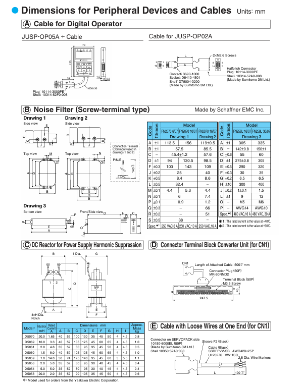
Noise filter FN2070-6/07 (single-phase) suppresses power side electromagnetic interference 250VAC, 6A, insertion loss ≥ 25dB
FN258L-16/07 (three-phase) three-phase system harmonic suppression 480VAC, 16A, insertion loss ≥ 30dB
DC reactor X5054 (SGDS) reduces input current harmonic inductance by 5.0mH and rated current by 5.0A
X5059 (SGDH) three-phase system harmonic suppression inductor 1.0mH, rated current 14.0A
Electromagnetic contactor HI-11J (20A) controls the power on/off of amplifier 250VAC, 20A, with surge absorber
Digital operator JUSP-OP05A (SGDS) amplifier parameter configuration/monitoring 1m connection line, supports parameter upload and download
JUSP-OP02A-2 (SGDH) extension function debugging supports self-tuning and alarm traceability
Selection process and order reference
(1) Selection steps
Clear requirements: Determine load torque, speed, positioning accuracy, installation space, and power supply type (single-phase/three-phase)
Motor selection: Match the outer diameter and model of the motor according to the torque speed requirements (refer to the torque speed characteristic curve)
Amplifier selection: Choose SGDS/SGDH series according to motor capacity and power supply type to ensure that the output current covers the motor requirements
Peripheral device matching: Select circuit breakers, filters, and reactors based on amplifier power, and choose dedicated cables according to wiring length
Parameter confirmation: Check the ratio of motor moment of inertia to load moment of inertia (recommended ≤ 10:1) to ensure dynamic response performance
(2) Motor amplifier adaptation table
Motor model compatible with SGDS amplifier compatible with SGDH amplifier power supply type
SGMCS-02B/05B/07B 02F/02A 02AE single-phase 100V/200V
SGMCS-04C/10C/14C 04F/04A 04AE single-phase 100V/200V
SGMCS-08D/17D/25D 04F/04A 04AE single-phase 200V
SGMCS-16E/35E 08A 08AE single-phase 200V
SGMCS-45M/80M/1AM -10AE/15AE/20AE Three phase 200V
SGMCS-80N/1EN/2ZN-15AE/30AE three-phase 200V
(3) Selection of specialized cables
Recommended cable types, applicable scenarios, length specifications
Motor power cable JZSP-CMM60-03 small capacity motor (B/C/D type) 3/5/10/15/20m
JZSP-CMM00-03 Medium Capacity Motor (M/N Type) 3/5/10/15/20m
Encoder cable JZSP-CMP60-05 small capacity motor encoder connection 5/10/15/20m
JZSP-CMP00-03 Medium Capacity Motor Encoder Connection 3/5/10/15/20m
I/O signal cable JZSP-CSI01-1 (SGDS) amplifier and controller connection 1/2/3m
JZSP-CKI01-1 (SGDH) Extended I/O Signal Connection 1/2/3m
Key points for installation and maintenance
(1) Mechanical installation specifications
Installation direction: Vertical installation (amplifier), horizontal fixing of motor flange surface to avoid tilting and stress
Spacing requirement: Reserve ≥ 30mm heat dissipation space around the amplifier, and the flatness of the coupling surface between the motor and the load should be ≤ 0.02mm
Fixed screws: Use high-strength screws of grade 10.9 and tighten them according to the torque requirements of the model (M4: 3.6N · m, M5: 7.8N · m, M6: 14.7N · m)
(2) Maintenance cycle and matters
Daily maintenance: Clean the dust on the surface of the motor, check that the cables are not damaged and the joints are not loose
Regular inspection: Measure the insulation resistance of the motor (≥ 10M Ω) every 6 months, and check the stability of the encoder signal annually
Component replacement: amplifier cooling fan (4-5 years), electrolytic capacitor (7-8 years), motor bearings (5000 hours or 5 years)
Troubleshooting: When an alarm occurs, first disconnect the power and check the wiring. Then, read the alarm code through the operator and troubleshoot the cause according to the manual
Application scenarios and advantages adaptation
(1) Core application areas
Semiconductor manufacturing equipment: wafer handling robotic arm, chip inspection platform
Electronic assembly equipment: SMT machine, soldering machine, precision dispensing machine
Testing and measuring equipment: IC testing handler, optical testing platform
LCD panel equipment: panel handling, polarizer bonding, laser cutting
(2) Advantages of scene adaptation
High precision positioning scenario: Backless design meets ± 1 μ m positioning requirements, suitable for chip packaging and precision bonding
Low noise environment: No gear meshing noise, suitable for clean rooms and laboratory equipment
High torque and low-speed scenario: Directly drive the load without the need for a gearbox, suitable for heavy-duty workbenches and rotating indexing discs
Miniaturization design: Compact structure reduces equipment volume, suitable for automation equipment with limited space
- OMRON
- ABB
- General Electric
- EMERSON
- Honeywell
- HIMA
- ALSTOM
- Rolls-Royce
- MOTOROLA
- Rockwell
- Siemens
- Woodward
- YOKOGAWA
- FOXBORO
- KOLLMORGEN
- MOOG
- KB
- YAMAHA
- BENDER
- TEKTRONIX
- Westinghouse
- AMAT
- AB
- XYCOM
- Yaskawa
- B&R
- Schneider
- KONGSBERG
- NI
- WATLOW
- ProSoft
- SEW
- ADVANCED
- Reliance
- TRICONEX
- METSO
- MAN
- Advantest
- STUDER
- DANAHER MOTION
- Bently
- Galil
- EATON
- MOLEX
- DEIF
- B&W
- ZYGO
- Aerotech
- DANFOSS
- Beijer
- Moxa
- Rexroth
- Johnson
- WAGO
- TOSHIBA
- BMCM
- SMC
- HITACHI
- HIRSCHMANN
- Application field
- XP POWER
- CTI
- TRICON
- STOBER
- Thinklogical
- Horner Automation
- Meggitt
- Fanuc
- Baldor
- SHINKAWA
- Other Brands
- UniOP
- KUKA
- Iba
- Beckhoff
-
 Basler DECS-200-2L Digital Excitation Control
 -
 Basler BE1-47N Voltage Phase Sequence Relay
 -
 Basler AEC63-7 Analog Excitation Controller 220-277V
 -
 Basler BE1-50/51B-107 Overcurrent Relay
 -
 Basler Electric BE1‑32R BE1‑E1P‑BON0F Protective Relay
 -
 Basler BE1-25 Solid State Time Overcurrent Relay M1EA6PA5S1F
 -
 Basler MVC 232 Manual Voltage Control Module 90 37000 103 60VAC 55VDC
 -
 Basler RAL6144-16GM Racer GigE Line Scan Camera
 -
 Basler SSR 63-12 Static Voltage Regulator
 -
 Basler BE1-51A Overcurrent Relay
 -
 Basler BE1-87T Solid State Protective Relay
 -
 Basler SR4A2B01B3A Static Voltage Regulator
 -
 Basler SSR 32-12 Static Voltage Regulator
 -
 Basler TRR00696 Transformer 1KVA 115V
 -
 Basler DECS-100-B15 AVR Replacement
 -
Basler BE1-27 Under-Voltage Relay
-
 Basler ACA2000-50GM Interface Module
 -
 Basler AEC63-7 Analog Excitation Controller
 -
 Basler PRS 250 Veri-Sync Relay
 -
 Basler SR4A-2B15B3A Static Voltage Regulator
 -
Basler BE1-32R Power Relay
-
Basler SR8A-2B06B3E Static Voltage Regulator
-
Basler BE1-81 O/U Frequency Relay
-
 Basler BE1-51A-K2E-W6M-B1N0F Overcurrent Relay
 -
Basler BE1-851 Overcurrent Relay G3A1S1 – 48-125V AC/DC
-
 Basler BEI-51 Overcurrent Relay – NSN 5945-01-293-2363
 -
Basler Electric L301KC Protective Relay – L301KC
-
 Basler DECS-100-B15 Automatic Voltage Regulator – Generator AVR
 -
 Basler SR4A-2B15B3A Static Voltage Regulator – SR4A2B15B3A
 -
 Basler UF 312 Under Frequency Protective Module – 9094700100
 -
Basler Electric MVC 232 Manual Control Module – 60VAC 55VDC 20A
-
Basler PRS 250 Veri-Sync Relay – Generator Synchronizing Relay
-
 Basler DECS-100-A05 Digital Regulator Review
 -
 Basler AEM-2020 Analog Expansion Module Specs
 -
 Basler DECS-100-B15 Digital Excitation Specs
 -
Basler Electric 9125600106 Regulator Component
-
Basler BE1-51A-K1E-W6M-B1N0F Overcurrent Relay
-
 Basler MVC-301 MVC 300 Excitation Controller
 -
 Basler SSR 32-12 Static Voltage Regulator
 -
 Basler 9-2849-00-101 Control Module
 -
Basler BE1-51A Overcurrent Relay
-
 Basler BE1-51/27R Overcurrent Relay
 -
 Basler BE1-51 Overcurrent Relay
 -
 Basler SR8A-2B15B3A Static Voltage Regulator
 -
 Basler BE32965001 Transformer and Timer Board
 -
 Basler 9174700100 EL200-7 Excitation Limiter
 -
 Basler BE2000E AVR Voltage Regulator
 -
Basler BE1-87G Differential Relay
-
 Basler BE21834001 Generator Control Module
 -
Basler DECS-100-B15 AVR
-
 Basler D90 96801 100 PCB Card
 -
 Basler XR2002F Voltage Regulator (110 VAC, 48-480 Hz)
 -
 Basler SR8A-2B14B3A Regulator
 -
 Basler 9561500100 Module
 -
 Basler DECS-400 BE1-11 System
 -
 Basler DECS-100-B15 Excitation Control
 -
 Basler SCP 210 Frequency Controller
 -
Basler SR4A-2B15B3A Static Voltage Regulator
-
Basler BE1-32R Power Relay
-
 Basler PIA2400-17GM Power Interface Adapter
 -
 Basler MVC 232 Manual Voltage Control Module
 -
 Basler SSR 32-12 Static Voltage Regulator
 -
Basler 5MW AVR Generator Voltage Regulator
-
 Basler VR63-4B Voltage Regulator
 -
Basler DECS-100-A05 AVR for Engine Generator
-
Basler DECS-100-B15 Automatic Voltage Regulator
-
Basler BE1-32R Directional Power Relay
-
Basler BE1-87B Differential Relay
-
 Basler UFOV 260A Protective Module
 -
 Basler 9-2614-02-100 PCB Rev M
 -
Basler DECS-100-B15 Digital AVR
-
 Basler 9284900103 PS DECS-400N
 -
 Basler D4N3H1U Intertie Protection
 -
 Basler DECS-100-B15 A15 AVR
 -
 Basler KR4F Voltage Regulator
 -
 Basler BE26434 T14 Transformer
 -
 Basler SR8A-2B15B3A Regulator
 -
 Westinghouse 774B472A12 AR Relay
 -
Basler DECS-100-B15 AVR
-
Basler XR2002F Regulator 110V
-
Basler SR125-E Static Regulator
-
Basler SSR 125-12 Regulator
-
Basler MOC2599 Motor Pot
-
 Basler BE1-DFPR Feeder Relay
 -
 Basler CBS 305 Current Boost
 -
Basler BE1-25 AutoSync
-
Basler MVC 300 Voltage Control
-
 Basler BE3-25A AutoSync
 -
 Basler KR7FF Static Regulator
 -
Basler 90-49000-100 Regulator
-
 Basler 880 kVA Dry Type Transformer Specs
 -
Basler Electric BE1-25 Sync-Check Relay Specs
-
 Basler SSR 125-12 Voltage Regulator Specs
 -
 Basler Electric BE1-851 Overcurrent Relay Review
 -
Basler Electric 149D930G02 Control Sub-Assembly
-
 Basler Electric BE1-81O/UT Frequency Relay Specs
 -
 Basler Electric BE1-51/27C Overcurrent Relay
 -
 Basler Electric 149D956G02 Industrial Component
 -
Basler Electric BE1-51A Overcurrent Relay Specs
-
 Basler Electric BE1-40Q Loss of Excitation Relay
 -
Basler DECS-200 Excitation Control System
-
 Basler DECS-200 Voltage Regulator 56-277V AC / 125V DC
 -
Basler BE1-87T Transformer Differential Relay
-
 Basler RDP-110-S1 Protection Relay
 -
 Basler BE1-700V Digital Protective Relay
 -
 Basler BE1-951 Overcurrent Protection System
 -
 Basler DECS-300 Digital Excitation Control
 -
 Basler DECS-200 Digital Excitation Control
 -
 Basler DECS-200-1C Excitation Control System
 -
Basler DECS-200-1L Digital Excitation Control
-
 Basler Electric BE1-GPS Generator Protection System
 -
Basler Electric DECS-200-1C Digital Excitation Controller
-
 Basler Electric DECS125-15 Excitation Control with Power Module
 -
Basler Electric BE1-87G Differential Relay
-
 Basler Electric BE1-11 Protection System I5A3M2P2N0EA00
 -
Basler Electric DECS-200-1C Excitation Control System
-
Basler Electric BE1-11g Generator Protection Relay
-
Basler Electric DECS 125-15-B2C1 V2.0.9 Excitation Control
-
Basler Electric BE1-81O/UT3ED1JA7N2F Frequency Relay
-
Basler Electric BE1-81O/UT3EE1YB7N1F Frequency Relay
-
 Basler Electric DECS-200-1L Digital Excitation Control System
 -
Basler DECS125-15-B2C1 Excitation Control
-
 Basler 9507900205 SSR Retrofit Voltage Regulator
 -
 Basler BE2000E Digital Voltage Regulator
 -
 Basler BE1-GPS Generator Protection System
 -
Basler DECS-250-CN1CN1N Digital Excitation Control
-
 Basler DGC-2020 Genset Controller
 -
Basler BE1-81O UT3ED1LA7N0F Frequency Relay (Variant)


