
Honeywell Sieger System 57 Modbus Interface Module Kit Operating Instructions
Model: RS422/485 (05701-A-0312), RS232 (05701-A-0313)
Document Number: MAN0502.PM6 Issue 04 October 99 05701M5006
Manufacturer: Honeywell (formerly Zellweger Analytics Limited)
Honeywell Sieger System 57 Modbus Interface Module Kit Operating Instructions
Basic information
Product Name: Sieger System 57 Modbus Interface Module Kit
Model: RS422/485 (05701-A-0312), RS232 (05701-A-0313)
Document Number: MAN0502.PM6 Issue 04 October 99 05701M5006
Manufacturer: Honeywell (formerly Zellweger Analytics Limited)
Safety Warning and Precautions
Warn
This device is not designed or certified for use in hazardous areas.
Suitable for indoor use only.
Avoid exposure to rain or moisture.
Precautions
Only use components and accessories approved by the System 57 control system.
To maintain safety standards, qualified personnel must regularly maintain, calibrate, and operate the System 57 control system.
Important Statement
Zellweger Analytics Limited shall not be liable for any failure to install and/or use the equipment in accordance with the corresponding version and revision of this manual.
The user of the manual should ensure that its content is completely consistent with the equipment to be installed and/or operated. If there are any questions, they should contact the company for consultation.
The company reserves the right to modify the information in this document without notifying any individual or organization.
Glossary
A1: Low or warning alarm level.
A2: Second warning alarm level.
A3: High or primary warning level.
LED: Light Emitting Diode.
LTEL: Long term exposure limit (8-hour time weighted average).
RFI: Radio Frequency Interference.
RH: Relative humidity.
STEL: Short term exposure limit (10 minute time weighted average).
TWA: Time weighted average.
Main functions and overview
Function: Provides digital communication between the System 57 control system and external computer systems, supports reading configuration, alarm status, and executing calibration programs.
Compatibility: Compatible with 5701, 5704, and 5704F control cards.
Communication standards: Supports RS485, RS422, and RS232 electrical standards.
Protocol: Operates as a Modbus RTU and supports the 02, 03, 04, 06, and 16 functions of the Modbus protocol.
Data isolation: The data signal is isolated from the System 57 power supply.
Configuration flexibility: Asynchronous serial links can be configured with baud rate, parity, and stop bits.
Way of working
System 57, as a Modbus Remote Terminal Unit (RTU), only transmits data in response to requests from the master device.
The host system (usually a PLC, DCS, or SCADA graphic package) serves as the main device to control the operation of the communication system.
Installation instructions
Preparation before installation
Confirm the type of engineering card, Modbus interface kit can only be installed on Mk 2 engineering cards.
Unpack and inspect the contents of the kit to ensure completeness and no transportation damage.
Installation steps
Cut off all power to the System 57 rack.
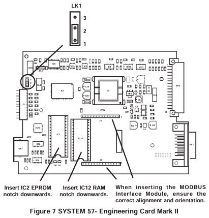
Remove the engineering card, insert the software upgrade EPROM integrated circuit into the IC2 socket of the engineering card, and insert the RAM expansion integrated circuit into the IC12 socket.
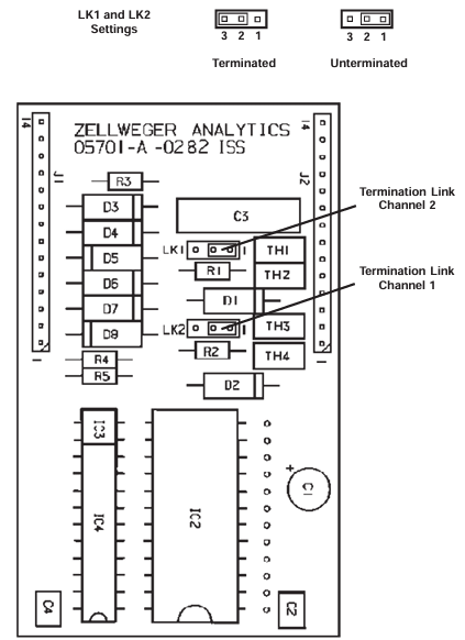
Replace the short-circuit link LK1 of the engineering card.
For RS485/422 modules, set the terminal resistance as needed.
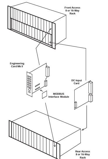
Insert the Modbus interface module into the J1 and J2 sockets of the engineering card and reinstall the engineering card.
On site connection
RS485/422 interface: Connect through the auxiliary terminal block TB2 on the DC input card, use shielded twisted pair cable, pay attention to correctly terminating the transmission line, and avoid signal interference.
RS232 interface: also connected through TB2 of DC input card, using high-quality multi-core shielded cable, following the connection specifications of RS232 standard.
Configure Modbus functionality
Host configuration
It is recommended to configure the host to retry at least twice when communication frames are lost.
System 57 configuration
Communication parameters: configurable modes (RS422, RS485, RS232), baud rate, stop bit, parity check, etc.
Address setting: Each rack needs to specify a unique Modbus master address, and when using RS485 half duplex communication and enabling the secondary bus, a secondary address also needs to be set.
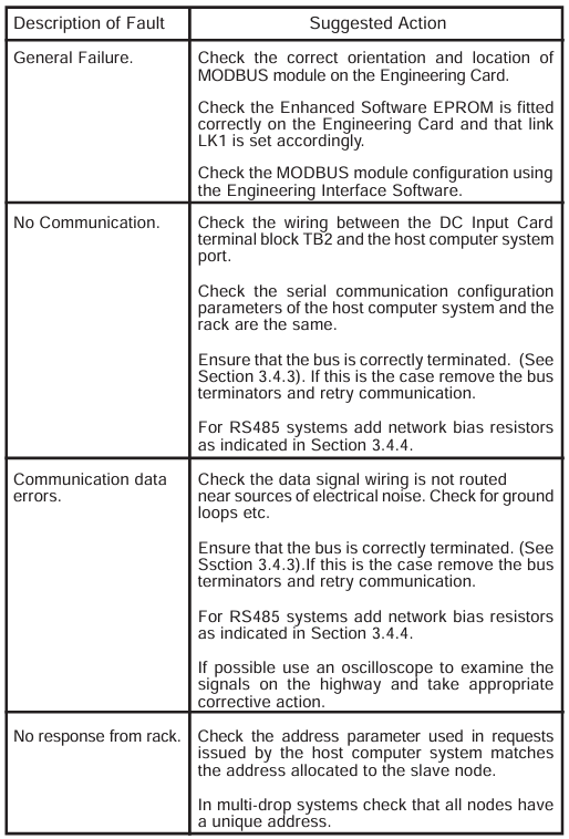
Debugging and Maintenance Instructions
Start program
Ensure that the system power is turned off, reconnect the power, and verify that the LED on the front panel of the engineering card flashes normally and the green POWER ON indicator light remains on.
After the power on suppression time, ensure that the gas detection system operates normally.
Turn on the host system and initiate Modbus master operation.
Simulate alarm conditions, check if the host can correctly detect and take corresponding actions, repeat the test and clear the simulated alarm.
maintenance
The Modbus interface functionality should be regularly tested according to the maintenance procedures in the control system user manual.
Operating instructions
Mainly used to connect gas detection systems to factory control systems, providing centralized monitoring of system status, usually with graphical displays.
The host system needs to be programmed to interpret the signals and status data provided by the System 57 control system.
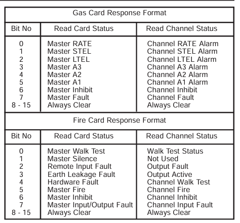
It is recommended that the host system be programmed to use Function 02 to collect alarm and status data from all channels. If the alarm function needs to be reset, Function 06 or 16 should also be implemented.
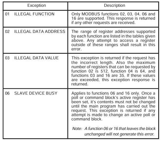
Modbus Function Reference
Supported Features
Function 02: Read input status, can read channel status bits, each sub channel has 11 status bits.
Function 03: Read the hold register. The host can read the contents of the hold register and can read up to 35 registers per frame.
Function 04: Read input registers, with two types of input registers: analog signal value and animation value. A maximum of 64 registers can be read per frame.
Function 06: Preset a single hold register.
Function 16: Preset multiple hold registers, up to 35 registers can be set per frame.
Specification parameters
Environmental parameters
Working temperature: -5 ° C to+55 ° C.
Storage temperature: -25 ° C to+55 ° C.
Humidity: 0 to 90% RH (non condensing).
EMC/RFI compliance
Compliant with EN50081 Part 1 and Part 2 (EMC/RFI Generic Emission) and EN50082 Part 1 and Part 2 (EMC/RFI Generic Immunity).
Serial communication
Format: Asynchronous serial data.
Data bit: 8.
Speed: 19200, 9600, 4800, 2400 baud.
Stop position: 1 or 2.
Parity check: odd, even, or none.
Mode: Half duplex.
Modbus protocol
Mode: RTU.
Supported functions: 02, 03, 04, 06, and 16.
RS485/422 interface module
Power supply: Powered by the engineering card.
Power consumption: maximum 1.5W.
Weight: 30g.
On site terminal: 2.5mm ² (14 AWG), located on the DC input card.
Cable type: It is recommended to use shielded twisted pair cables with separate grounding wires.
Input/Output: Two RS485 transceivers (Channel 1, Channel 2).
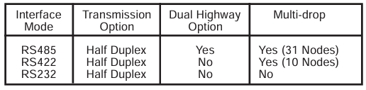
Working mode: single RS485 highway, dual RS485 highway (primary and secondary) RS422 highway。
Multi node capability: up to 31 nodes (RS485) or up to 10 nodes (RS422).
Maximum cable length: 1200m (3900ft).
Maximum data rate: 19.2k baud.
RS232 module
Power supply: Powered by the engineering card.
Power consumption: Maximum 0.75W.
Weight: 30g.
On site terminal: 2.5mm ² (14 AWG), located on the DC input card.
Cable type: It is recommended to use shielded multi-core wires.
Input/Output: Two data sets (RXD, TXD) and two handshakes (DTR, DSR).
Maximum cable length: 15m (49ft).
Maximum data rate: 9600 bits per second.
- OMRON
- ABB
- General Electric
- EMERSON
- Honeywell
- HIMA
- ALSTOM
- Rolls-Royce
- MOTOROLA
- Rockwell
- Siemens
- Woodward
- YOKOGAWA
- FOXBORO
- KOLLMORGEN
- MOOG
- KB
- YAMAHA
- BENDER
- TEKTRONIX
- Westinghouse
- AMAT
- AB
- XYCOM
- Yaskawa
- B&R
- Schneider
- KONGSBERG
- NI
- WATLOW
- ProSoft
- SEW
- ADVANCED
- Reliance
- TRICONEX
- METSO
- MAN
- Advantest
- STUDER
- DANAHER MOTION
- Bently
- Galil
- EATON
- MOLEX
- DEIF
- B&W
- ZYGO
- Aerotech
- DANFOSS
- Beijer
- Moxa
- Rexroth
- Johnson
- WAGO
- TOSHIBA
- BMCM
- SMC
- HITACHI
- HIRSCHMANN
- Application field
- XP POWER
- CTI
- TRICON
- STOBER
- Thinklogical
- Horner Automation
- Meggitt
- Fanuc
- Baldor
- SHINKAWA
- Other Brands
- UniOP
- KUKA
- Iba
- Beckhoff
- ADLINK
-
 Basler Electric BE1-700 Digital Protective Relay
 -
 Basler Electric SR8A-2B01B3A Static Voltage Regulator
 -
 Basler Electric SR4A-2B01B3E Static Voltage Regulator
 -
 Basler Electric 9017709102 PC Board
 -
Basler Electric SR4A-2B01B3A Static Voltage Regulator
-
 Basler Electric PRS-250 Veri-Sync Relay
 -
 Basler Electric 9066800102 Excitation Support System
 -
 Basler Electric BE1-87G Generator Differential Relay 9 1708 18 100
 -
 Basler Electric 36T865-2 BE03752001 Power Supply
 -
 Basler Electric M-300 149D940G02 Power Supply
 -
 Basler Electric ACA2040-25GM 4Mp 25Fps Area Scan Camera
 -
 Basler BE1-87G-S1A-A1C-A0N0 Differential Relay
 -
 Basler SR8A-2B06B3E Static Regulator SR8A2B06B3E
 -
 Basler SCP-210 Frequency Controller 9095400100
 -
 Basler BE1-59-A3E-A1J-N1N3F Overvoltage Relay BE159A3EA1JN1N3F
 -
 Basler 9 2011 11 100 Bracket Mounted Terminal Unit
 -
Basler 9 1606 00 101 Voltage Regulator
-
 Basler CBS-377 Current Boost System 9109600102
 -
 Basler 8650C72 Exciter Control Module PCB Rev 5
 -
 Basler C2EE1PA0N1F BE1-32R Reverse Power Relay
 -
 ADLINK HPCI-14S12U - Industrial Control Backplane 12PCI Backplane PCI-14S Passive Backplane
 -
-0010.png) ADLINK PCIe-GIE74C - image acquisition card 4-CH GigE Vision PoE+ Frame Grabber
ADLINK PCIe-GIE74C - image acquisition card 4-CH GigE Vision PoE+ Frame Grabber -
-0010_1.png) ADLINK PCI-8164 - control card 4-Axis Advanced Motion Controller Board
ADLINK PCI-8164 - control card 4-Axis Advanced Motion Controller Board -
 ADLINK PCIe-U304 - 4 Port USB3 PCIe Frame Grabbers USB Screw Hole Card
 -
 ADLINK PCI-9112 - Multi-Function Data Acquisition Card DAQ Card
 -
 ADLINK PCI-7432 - 51-12013-0A50 4-CH Isolated Numérique I/O PCI Cartes Digital I/O Card
 -
 ADLINK PCA-6106P3-0C1 REV.C1 - backplane 6-Slot Passive Backplane Board
 -
 ADLINK PCI-7224 - 24-CH Opto-Isolated Digital I/O PCI Board
 -
 ADLINK CPCI-7433R(G) - Digital Input Board Rear I/O CompactPCI Card
 -
 ADLINK EBP-13E4 - 51-46703-0A30 Industrial PC Backplane Passive Backplane
 -
 ADLINK PCIE-HDV62 - Image acquisition card High Definition Video Frame Grabber
 -
 ADLINK EBP-13E4 - 51-46703-0A30 Industrial Backplane Board Passive Backplane
 -
 ADLINK 90111-B1 / CPCI-6770 - PCB CPU MODULE CompactPCI Single Board Computer
 -
 ADLINK PCI-7248 - DATA ACQUISITION PCI CARD 48-CH Parallel Digital I/O Board
 -
 ADLINK PCI-7230 - 51-12003-0a50 board PCI7230 32-CH Isolated Digital I/O Card
 -
 ADLINK PCI2A000CB - 51-20000-0B30 Multi-Function DAQ Card Baseboard
 -
 ADLINK PCI-8134-005 - 4-Axis Motion Controller Card
 -
 ADLINK PCI-7224 - 24-CH Opto-Isolated Digital I/O PCI Card
 -
 ADLINK PCI-7434 - 64-CH Isolated Digital Output Card
 -
 ADLINK PCI-8132 - motion control card 2-Axis Servo & Stepper Controller
 -
 ADLINK PCI-8134 - Motion Controller PCI Card 4-Axis Controller Board
 -
 ADLINK PCI-8164 - Motion Control Card 51-12406-0A40 4-Axis Controller
 -
 ADLINK 51-12001-0C20 - Circuit Board Data Acquisition Interface Module Hardware
 -
 ADLINK NuPR0-840 - industrial control motherboard Full-Size PICMG CPU Board
 -
 ADLINK PCI-7444 - 51-12023-0A10 card 128-CH Isolated Digital Output Board
 -
 ADLINK PCI-1612B - data acquisition card 4-Port RS-232/422/485 Serial Communication Card
 -
 ADLINK PCI-6208V 009 - 8/16-CH 16-Bit Analog Output Cards PCB-I-E-482=6BX3
 -
 ADLINK NUPRO-935A/LV - industrial control motherboard Full-Size PICMG SBC Board
 -
 ADLINK PCI-9114DG - Multi-Function DAQ Card Data Acquisition PCI Card
 -
 ADLINK ACL-7130 - Data acquisition card Isolated Digital I/O Board
 -
 ADLINK ABX-6300D-4E1-BP - board ABX6300D4E1BP Video Interface Expansion Card
 -
 ADLINK CPCI-6940 - CPCI-6940/D1539/M16-0(EA)-000E 6U CompactPCI Processor Board
 -
 ADLINK NuPRO-760 - industrial control motherboard Half-Size PICMG SBC CPU Board
 -
 ADLINK IMB-M42H (G)-0020 - industrial control motherboard LGA1155 Micro-ATX Mainboard
 -
 ADLINK RTV-24 / PCI-MP4S - 51-12519-1C30 4-Channel Real Time Video Capture Board
 -
 ADLINK PCI-8134 - 4-Axis Servo & Stepper Motion Controller Card
 -
 ADLINK MXC-6101D - V.PC000.002.ST.00 Box PC Configurable Embedded Computer
 -
.png) ADLINK PCI-8134A - 51-12421-0A10 Motion Control Card 4-Axis Controller Card
ADLINK PCI-8134A - 51-12421-0A10 Motion Control Card 4-Axis Controller Card -
 ADLINK DIN-100S / DIN-100SA1 - Technology SCSI-II TB 100-PIN Terminal Block Board
 -
.png) ADLINK DIN-812M001 / DIN812M001 - 51-14034-0A1 51140340A1 Terminal Module Breakout Interface
ADLINK DIN-812M001 / DIN812M001 - 51-14034-0A1 51140340A1 Terminal Module Breakout Interface -
_1.png) ADLINK PCI-8164 - Servo motion control 4-Axis Advanced Controller Card
ADLINK PCI-8164 - Servo motion control 4-Axis Advanced Controller Card -
 ADLINK PCIe-GIE64 - Acquisition card GigE Vision PoE+ Frame Grabber
 -
 ADLINK M-302 - Industrial control motherboard ATX PC Board Mainboard
 -
 ADLINK PCI-8134 - Motion Controller PCI Card 4-Axis Controller Board
 -
 ADLINK PCI-RTV24 - Image capture card Analog Video Frame Grabber
 -
 ADLINK PCI-8102 - Motion control card 2-Axis Servo & Stepper Controller Board
 -
 ADLINK PCI-9112 REV.B1 - Card Multi-Function Data Acquisition Card
 -
 ADLINK HSI-DI32-M-N / HSL-TB32-M-DIN - Discrete I/O MODULE Distributed Automation Module System
 -
 ADLINK PCI-7296 - IO card REV.A3 96-CH Parallel Digital I/O Card
 -
-0020.png) ADLINK DIN-814P-A4 / 814Y - terminal board Motion Control Interface Block
ADLINK DIN-814P-A4 / 814Y - terminal board Motion Control Interface Block -
 ADLINK DIN-814P-A4 - 51-14056-0A10 PCB-I-E-2736=ZA01 Screw Terminal Board Breakout
 -
 ADLINK M-322 - motherboard Industrial Control Computer Mainboard
 -
 ADLINK NUPRO-406 REV:B1 - industrial control motherboard Full-Size PICMG CPU Board
 -
 ADLINK AMP-204C - card DSP-Based 4-Axis Advanced Pulse-Train Controller
 -
 ADLINK HPCI14S REV.B1 - industrial computer baseboard 14-Slot Passive Backplane
 -
 ADLINK PCI-7250 - 8-CH Relay Output & 8-CH Isolated DI PCI Card
 -
 ADLINK EBP-13E2 - baseplate Passive Backplane Industrial Computer Chassis Board
 -
 ADLINK LPCI-3488A - PCI-GPIB card 51-12801-0A30 acquisition card IEEE-488 Interface Board
 -
 ADLINK PCI-6216V-GL - 51-12201-0C30 16-CH 16-Bit Voltage Analog Output Card
 -
 ADLINK ACL-8454 - 16-CH Isolated Digital I/O & 4-CH Counter Card
 -
 ADLINK HPCI-9S7U - backplane Passive Backplane Compatible with NuPRO-A301 852 841 842
 -
 ADLINK DAQ-2010-007 - Simultaneous-Sampling Multi-Function Data Acquisition Card
 -
 ADLINK MP-C154 - 51-64205-0A10 Motion Control Card 4-Axis Controller Board
 -
 ADLINK MXE-202/mSSD16B/WiFi-BT - Matrix Rugged I/O Platform Embedded Fanless Computer
 -
 ADLINK CM-920-R-17 - PC/104-Plus Single Board Computer Module Intel Celeron M
 -
 ADLINK PCI-7250 NSMP - 8-CH Relay Output & 8-CH Isolated DI Card
 -
 ADLINK PCI-8164 - 4-Axis Motion Controller PCI Card W/ Cable and Breakout Box
 -
 ADLINK EMX-100 - Ethernet-based 4-axis Motion Controllers Distributed Motion Module
 -
.png) ADLINK PCI-8134A - Press control card 4-Axis Motion Controller Board
ADLINK PCI-8134A - Press control card 4-Axis Motion Controller Board -
 ADLINK M-845EG REV:3.2 - industrial motherboard Pentium 4 Socket 478 Micro-ATX
 -
 ADLINK PCI-9114A Rev A2 DG - card High-Resolution Multi-Function Data Acquisition Board
 -
 ADLINK IEC-915GV - REV 1.1 Industrial motherboard Socket 478 CPU Board
 -
 ADLINK PCI-9111DG(G) - Data Acquisition Card Multi-Function DAQ Card
 -
 ADLINK HPCI-15S10 REV:B2 - Industrial computer base plate Passive Backplane Board
 -
 ADLINK NuPR0-840 / NuPR0-840DV - industrial control motherboard Full-size PICMG CPU Board
 -
 ADLINK RTV-24 / PCI-MP4S - 51-12519-1C30 4-Channel Real Time Video Capture Board
 -
 ADLINK NUPRO-780 - industrial control motherboard Pentium III Single Board Computer
 -
 ADLINK PCI-7296 - 0050 card 96-CH Opto-Isolated Parallel DIO Card Set
 -
-0040.png) ADLINK NUPRO-780 - industrial control motherboard PICMG Full-Size SBC
ADLINK NUPRO-780 - industrial control motherboard PICMG Full-Size SBC -
 ADLINK PCI-7248 - 51-12006-0A3 002 Pci 7248 48-CH Parallel Digital I/O Card
 -
 ADLINK PCI-7230 - 32-CH Isolated Digital I/O Card
 -
 ADLINK AMP-204C - motion control card 4-Axis Advanced Controller Board
 -
.png) ADLINK PCI-1714UL - Card Ultra High-Speed 4-CH Simultaneous Sampling DAQ
ADLINK PCI-1714UL - Card Ultra High-Speed 4-CH Simultaneous Sampling DAQ -
 ADLINK NuPRO-E330 - industrial computer equipment motherboard PICMG 1.3 SHB SBC
 -
 ADLINK AMP-204C - DSP-Based 4-Axis Advanced Pulse-Train Motion Controller Module
 -
 ADLINK PCI-7256 - 001 51-12206-0A2 REV.A2 LPCI-7256 16-CH Latching Relay Output Card
 -
 ADLINK ND6050 - NUDAM DIGITAL I/0 MODULE Distributed I/O Unit
 -
 ASEM BM100 - Box PC Embedded Fanless Industrial Computer
 -
-3650.png) ADLINK PCI-7250 - PCI Acquisition Card 8-CH Relay Output & Isolated DI Board
ADLINK PCI-7250 - PCI Acquisition Card 8-CH Relay Output & Isolated DI Board -
 ADLINK PCI-8164 - Servo motion control 4-Axis Controller Card
 -
 Basler XR2002F Voltage Regulator 9139400101
 -
Basler 2D80367G23 DXCB De-Excitation Module 1200V 5000A
-
Basler SR4A-2B15B3A Static Regulator 120V 50/60Hz
-
 Basler SSR 125-12NF Static Regulator 9 1859 00 106
 -
 Basler BE1-BPR Breaker Protection Relay 9272000315
 -
 Basler SSR 63-12 Static Regulator 9 1859 00 101
 -
 Basler AEM-2020 Analog Expansion Module
 -
 Basler BE 25231-001 Transformer BE25231001
 -
Basler MVC 108 Manual Voltage Control 9037000102
-
 Basler PSS-100-Y5 Power System Stabilizer 0.1-5.0Hz
 -
Basler Electric BE1A-25-M1G-A6T-N4V1F Sync-Check Relay
-
 Basler Electric SR8A2B10B1A Static Voltage Regulator
 -
Basler Electric SR8A2B10B1A Static Voltage Regulator
-
Basler Electric SSR 125-12 Static Voltage Regulator 9185900102
-
 Basler Electric 90-73900-102 Power Supply (Westinghouse 2374A07G03)
 -
 Basler Electric 9400200117 Control Power Unit 12/24VDC 20W
 -
Basler Electric BE1-87G Solid State Generator Differential Relay
-
 Basler Electric BE1-32R Style C3ED1TA0S1F Solid State Protective Relay


