
Honeywell Sieger System 57 Modbus Interface Module Kit Operating Instructions
Model: RS422/485 (05701-A-0312), RS232 (05701-A-0313)
Document Number: MAN0502.PM6 Issue 04 October 99 05701M5006
Manufacturer: Honeywell (formerly Zellweger Analytics Limited)
Honeywell Sieger System 57 Modbus Interface Module Kit Operating Instructions
Basic information
Product Name: Sieger System 57 Modbus Interface Module Kit
Model: RS422/485 (05701-A-0312), RS232 (05701-A-0313)
Document Number: MAN0502.PM6 Issue 04 October 99 05701M5006
Manufacturer: Honeywell (formerly Zellweger Analytics Limited)
Safety Warning and Precautions
Warn
This device is not designed or certified for use in hazardous areas.
Suitable for indoor use only.
Avoid exposure to rain or moisture.
Precautions
Only use components and accessories approved by the System 57 control system.
To maintain safety standards, qualified personnel must regularly maintain, calibrate, and operate the System 57 control system.
Important Statement
Zellweger Analytics Limited shall not be liable for any failure to install and/or use the equipment in accordance with the corresponding version and revision of this manual.
The user of the manual should ensure that its content is completely consistent with the equipment to be installed and/or operated. If there are any questions, they should contact the company for consultation.
The company reserves the right to modify the information in this document without notifying any individual or organization.
Glossary
A1: Low or warning alarm level.
A2: Second warning alarm level.
A3: High or primary warning level.
LED: Light Emitting Diode.
LTEL: Long term exposure limit (8-hour time weighted average).
RFI: Radio Frequency Interference.
RH: Relative humidity.
STEL: Short term exposure limit (10 minute time weighted average).
TWA: Time weighted average.
Main functions and overview
Function: Provides digital communication between the System 57 control system and external computer systems, supports reading configuration, alarm status, and executing calibration programs.
Compatibility: Compatible with 5701, 5704, and 5704F control cards.
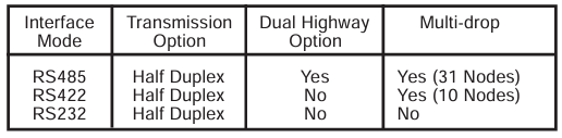
Communication standards: Supports RS485, RS422, and RS232 electrical standards.
Protocol: Operates as a Modbus RTU and supports the 02, 03, 04, 06, and 16 functions of the Modbus protocol.
Data isolation: The data signal is isolated from the System 57 power supply.
Configuration flexibility: Asynchronous serial links can be configured with baud rate, parity, and stop bits.
Way of working
System 57, as a Modbus Remote Terminal Unit (RTU), only transmits data in response to requests from the master device.
The host system (usually a PLC, DCS, or SCADA graphic package) serves as the main device to control the operation of the communication system.
Installation instructions
Preparation before installation
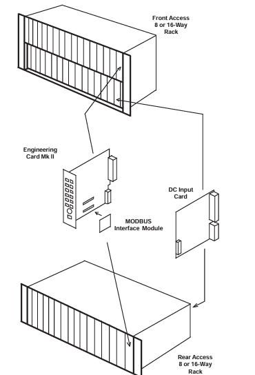
Confirm the type of engineering card, Modbus interface kit can only be installed on Mk 2 engineering cards.
Unpack and inspect the contents of the kit to ensure completeness and no transportation damage.
Installation steps
Cut off all power to the System 57 rack.
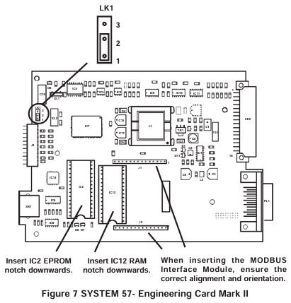
Remove the engineering card, insert the software upgrade EPROM integrated circuit into the IC2 socket of the engineering card, and insert the RAM expansion integrated circuit into the IC12 socket.
Replace the short-circuit link LK1 of the engineering card.
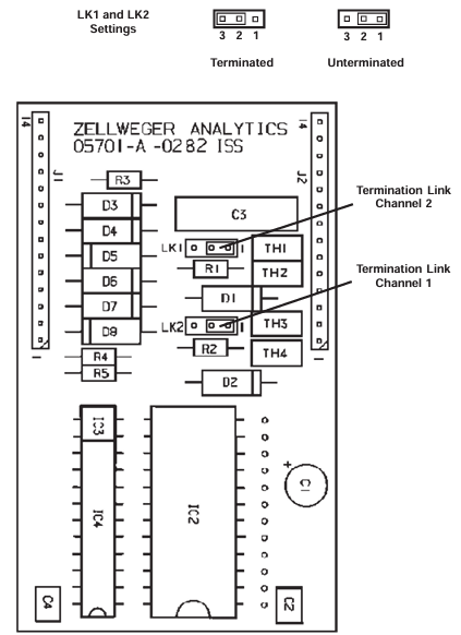
For RS485/422 modules, set the terminal resistance as needed.
Insert the Modbus interface module into the J1 and J2 sockets of the engineering card and reinstall the engineering card.
On site connection
RS485/422 interface: Connect through the auxiliary terminal block TB2 on the DC input card, use shielded twisted pair cable, pay attention to correctly terminating the transmission line, and avoid signal interference.
RS232 interface: also connected through TB2 of DC input card, using high-quality multi-core shielded cable, following the connection specifications of RS232 standard.
Configure Modbus functionality
Host configuration
It is recommended to configure the host to retry at least twice when communication frames are lost.
System 57 configuration
Communication parameters: configurable modes (RS422, RS485, RS232), baud rate, stop bit, parity check, etc.
Address setting: Each rack needs to specify a unique Modbus master address, and when using RS485 half duplex communication and enabling the secondary bus, a secondary address also needs to be set.
Debugging and Maintenance Instructions
Start program
Ensure that the system power is turned off, reconnect the power, and verify that the LED on the front panel of the engineering card flashes normally and the green POWER ON indicator light remains on.
After the power on suppression time, ensure that the gas detection system operates normally.
Turn on the host system and initiate Modbus master operation.
Simulate alarm conditions, check if the host can correctly detect and take corresponding actions, repeat the test and clear the simulated alarm.
maintenance
The Modbus interface functionality should be regularly tested according to the maintenance procedures in the control system user manual.
Operating instructions
Mainly used to connect gas detection systems to factory control systems, providing centralized monitoring of system status, usually with graphical displays.
The host system needs to be programmed to interpret the signals and status data provided by the System 57 control system.
- OMRON
- ABB
- General Electric
- EMERSON
- Honeywell
- HIMA
- ALSTOM
- Rolls-Royce
- MOTOROLA
- Rockwell
- Siemens
- Woodward
- YOKOGAWA
- FOXBORO
- KOLLMORGEN
- MOOG
- KB
- YAMAHA
- BENDER
- TEKTRONIX
- Westinghouse
- AMAT
- AB
- XYCOM
- Yaskawa
- B&R
- Schneider
- KONGSBERG
- NI
- WATLOW
- ProSoft
- SEW
- ADVANCED
- Reliance
- TRICONEX
- METSO
- MAN
- Advantest
- STUDER
- DANAHER MOTION
- Bently
- Galil
- EATON
- MOLEX
- DEIF
- B&W
- ZYGO
- Aerotech
- DANFOSS
- Beijer
- Moxa
- Rexroth
- Johnson
- WAGO
- TOSHIBA
- BMCM
- SMC
- HITACHI
- HIRSCHMANN
- Application field
- XP POWER
- CTI
- TRICON
- STOBER
- Thinklogical
- Horner Automation
- Meggitt
- Fanuc
- Baldor
- SHINKAWA
- Other Brands
- UniOP
- KUKA
- Iba
- Beckhoff
- ADLINK
-
 MICRO INNOVATION GF1-10TVB-100 Touch Panel
 -
 MICRO INNOVATION AG WINBLOC CAN-4AI/UI Analog Input Module
 -
 MICRO INNOVATION AG WINBLOC CAN-32DO/0.5A-P-2x16 Output Module
 -
 MICRO INNOVATION AG CAN-32DI/P-2X16 8551224182 Input Module
 -
 MICRO INNOVATION MK2-230/232-57 Circuit Board 85 28 200000
 -
 MICRO INNOVATION CAN-BRIDGE 8551224177 CAN Bridge
 -
 Micro Innovation MC2-430-10TVB-1-10 Panel 24VDC
 -
 MICRO INNOVATION MC2-432-57CQB-1-10 HMI Panel
 -
MICRO INNOVATION AG CAN-BRIDGE 85 51 224177 CAN Bridge
-
 MICRO INNOVATION CAN-4AI/UI Analog Input Module
 -
MICRO INNOVATION CAN-32DI/P-2X16 Input Module
-
 SIGMATEK MDD111 09-404-111 Drive Module
 -
 SIGMATEK DVI021 Display Interface Module
 -
 SIGMATEK 00-450-024 C-IPC Processor
 -
 SIGMATEK MDD-111 MDD111 Drive Module
 -
 SIGMATEK ICA011 20-102-011 Interface Module
 -
 SIGMATEK 01-250-010-D NC4Kompakt Control Module
 -
 SIGMATEK CRIF081 12-751-081 Interface Module
 -
 SIGMATEK S1026-8AF61-R4E-Z57 Drive Module
 -
 SIGMATEK 9305.081.02 9227.082.00 Control Module
 -
 Sigma Tek 5000B-36 Attitude Indicator
 -
 SIGMATEK CEZ201 12-051-201-O Counter Module
 -
 SIGMATEK DPS001 Power Supply Module
 -
 SIGMATEK 994 395 01z Via Interface Module
 -
 SIGMATEK PC411-K 01-310-411-K Industrial PC
 -
 SIGMATEK 9816.324.00 Demag NC4 Keyboard
 -
 SIGMATEK ET261 90010C-71 Operator Terminal
 -
 SIGMATEK DDI 164 05-006-164 Input Module
 -
 SIGMATEK CCP 082 C-DIAS Processor Module
 -
SIGMATEK CEZ201 12-051-201-O PLC Module
-
SIGMATEK MDD 1111 06178867 Drive Module
-
SIGMATEK S1 073-6AC61-RE-Y08-Z Drive Module
-
SIGMATEK MDD 111 Drive Module MDD111
-
 SIGMATEK CSDI161 Safety Module 12-891-161
 -
SIGMATEK C-IPC Processor 01-450-024
-
 SIGMATEK DIAS DAM122 Analog Mixing Module
 -
Sigma Tek 5000B-36 Attitude Gyro Indicator
-
 SIGMATEK TMS012 Motherboard Module 05-250-012-T
 -
 SIGMATEK CCP-531 PLC Module
 -
SIGMATEK DIAS DNC4 I/O Module 05-250-011
-
 SIGMATEK AI088 Analog Input Module
 -
 SIGMATEK CEZ201 Counter Module
 -
SIGMATEK CIC011 Industrial Computer Module
-
 SIGMATEK MDM021 Motor Drive Module
 -
 SIGMATEK DTO163 Digital Output Module
 -
SIGMA-TEK 5000B-36 Attitude Gyro
-
SIGMATEK DM161 Digital Input Module
-
SIGMATEK CCP-531 PLC Control Panel
-
 SIGMATEK HZS773 Touch Terminal Operator Panel
 -
SIGMATEK MDP101 3 KVA 45-65Hz Driver
-
 SIGMATEK ETV1251 Touch Panel 12-230-1251
 -
SIGMATEK CIO021 Safety Module 12-013-021
-
Sigma Tek 4000H-5 Directional Gyro
-
 SIGMATEK TAE531 I/O Module 01-240-531
 -
 SIGMATEK DAI081 Input Module 05-009-081
 -
 SIGMATEK DCP640 Drive Control Module
 -
 SIGMATEK DCP643 Slides Module A6-29
 -
SIGMATEK SCP011 Safety Module 20-890-011
-
SIGMATEK DDM 164-D Slides Module
-
 SIGMATEK C-IPC Processor 146267
 -
SIGMATEK ET3200 Display Screen
-
SIGMATEK CEZ221 C-DIAS Mixing Module
-
 SIGMATEK SDD120-2 DIAS Servo Drive
 -
SIGMATEK DIP011 05-058-011 Module
-
 Sigmatek DEC181 I/O Module
 -
SIGMATEK DCP640 DIAS Central Unit
-
SIGMATEK 00-450-024 C-IPC Industrial Computer
-
SIGMATEK AKM32C-ANCNR-B0 Servomotor
-
SIGMATEK DVI021 DIAS Power Module
-
SIGMATEK CTS051 12-053-051 Control Module
-
 SIGMATEK CTS022 Control Module
 -
 Sigmatek 01-250-010-D NC4Kompakt V2.1 Module
 -
 SIGMATEK Control Keyboard 01-285-042 Interface
 -
 SIGMATEK TO081 20-007-081 Digital Output Module
 -
 Sigmatek AKM73Q-ANCNGBB0 7.07kW Servo Motor
 -
Sigmatek DIP012 Demag 07024165 Processor Module
-
 SIGMATEK PC 411 Injection Molding Controller
 -
SIGMATEK CEZ201 12-051-201-O Processor Module
-
 SIGMATEK VI021 20-003-021 Digital Input Module
 -
SIGMATEK Computer C-IPC 144904 Industrial PC
-
 SIGMATEK 9307.083.01 9305.081.02 Industrial Module
 -
 SIGMATEK AI075 Analog Input Module
 -
 SIGMATEK HGT834-W Teaching Pendant
 -
Sigmatek CDI161 Digital Input Module
-
 SIGMATEK HGT834 Teaching Pendant
 -
 SIGMATEK CEZ201 12-051-201-O Module
 -
SIGMATEK Demag 9617.067.03 9708.244.00 Module
-
 SIGMATEK SCP010 Safety CPU Module
 -
SIGMATEK N100 20-011-100 Module
-
 SIGMATEK CNC 031 Positioning Output Module
 -
 Sigmatek 01-355-016 Control Module
 -
 Sigmatek MDM021 Digital Mixed Module
 -
Sigmatek DAI411 05-020-411 Analog Module
-
Attitude Gyro 1U367-232-2 Aircraft Instrument
-
 Sigma-Tek 5000B-36 Attitude Gyro 23-501-06-16
 -
Sigmatek HGT834-W Injection Molding Teach Pendant
-
Sigma Tek 5000EG Attitude Gyro 1U670-003-12
-
Sigmatek HGT834-W Teach Pendant
-
Sigmatek DEE011 05-068-011 Module
-
Sigmatek DIAS DCP643 Central Processing Unit
-
Sigmatek MDD111-1 DIAS Drive Axis Module
-
 Sigmatek DKL042 05-024-042 Terminal Module
 -
Sigmatek DM822 Control Module
-
Sigmatek CDM167 12-008-167-O Module
-
Sigmatek TAE151 Touch Display Unit
-
 Sigmatek DCC041 SLIDES Module 05-700-041-D
 -
Sigmatek AKM65M-ANC2GBB0 PM Servo Motor
-
Sigmatek ETT221 01-230-221 Operator Terminal
-
Sigmatek SLIDES DAM 124 Analog Module
-
Sigmatek AKM31C-ANCNGBB0 Servo Motor
-
Mannesmann Demag Sigmatek CP626 Central Unit
-
SIGMATEK 0332.554.03 Board 371071000154
-
 SIGMATEK 12-250-021 Base Plate Back Panel CM5V020
 -
SIGMATEK DM162 S-DIAS Digital Mix Module
-
DEMAG ERGOTECH 061 381 66 Sigmatek 9842.243.02 Circuit Board
-
 SIGMATEK CP313-1 PLC Module
 -
Sigmatek ETV0551-2 VARAN Touch Terminal
-
 Sigmatek SDM 081 FS S-Dias Safety Module
 -
 DEMAG 05-250-023 Ergotech Motherboard with Sigmatek TMS012
 -
Sigmatek CM5V020 12-250-023-K Wiring Base
-
Sigma Tek 5000B-37 Attitude Gyro Indicator
-
Sigmatek SDD120-2 DIAS Drive
-
 Sigmatek CME221 Memory Module
 -
Sigmatek DCP640 DIAS Central Unit
-
 Sigmatek STO040 Safety Output Module
 -
Sigmatek CET281 Control Panel
-
Sigmatek CIPC LX800 Demag NC5 CPU
-
Sigmatek DKL093 05-024-093 Terminal Module


