Welcome to the Industrial Automation website!
Product
Article
NameDescriptionContent

Honeywell Spyder® BACnet® Programmable Controllers
The PUB and PVB controllers are part of the Spyder family. The nine controllers are BACnet MS/TP network devices designed to control HVAC equipment. These controllers provide many options and advanced system features that allow state-of-the-art commercial building control. Each controller is programmable and configurable using the NIAGARA FRAMEWORK® software.
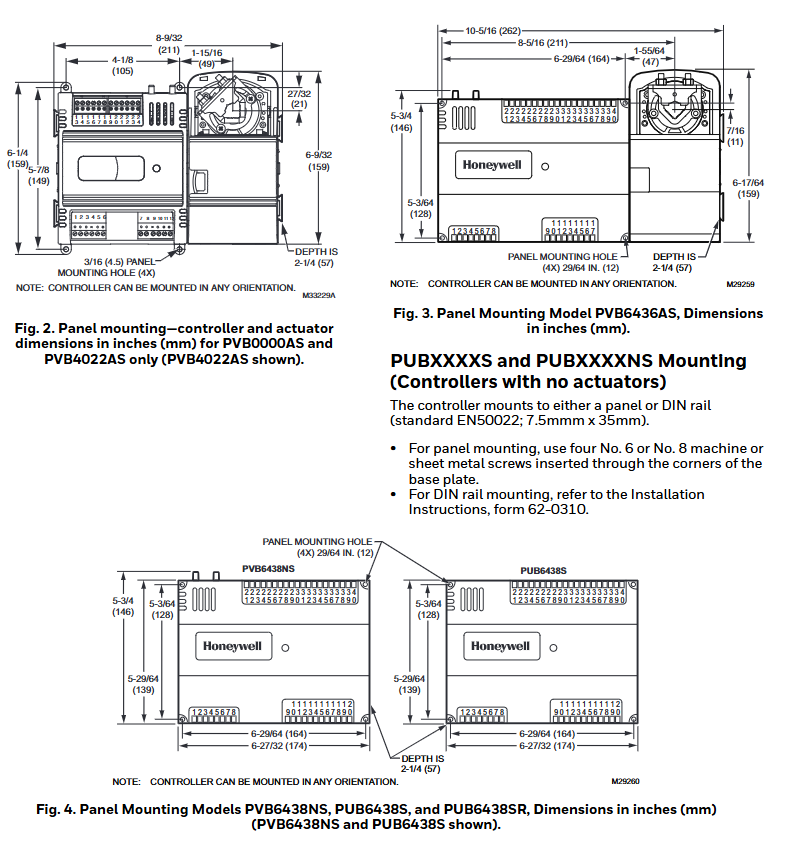
PUB6438S, PUB6438SR: 5.45 x 6.85 x 2.26 in. (13.84 x 17.40 x 5.74 cm)
Hardware (PVB0000AS, PUB1012S, PUB4024S, PVB4022AS, and PVB4024NS)
CPU
Each controller uses a 32 bit ATMEL ARM 7 microprocessor.
Memory Capacity
Flash Memory: 512 kilobytes. The controller is able to retain Flash memory settings for up to ten (10) years.
RAM: 128 kilobytes
Controller Status LED
The LED on the front of the controller provides a visual indication of the status of the device. When the controller receives power, the LED appears in one of the following allowable states, as described in Table 3.
Hardware (PUB6438S, PUB6438SR, PVB6436AS, and PVB6438NS)
CPU
Each controller uses a pair of microprocessors. The first is a 16-bit Texas Instruments MSP430 family microprocessor that is used to manage the Inputs, Outputs and Control. The second is a 32-bit ATMEL ARM 7 microprocessor that manages communication for the Spyder BACnet.
Memory Capacity
Flash Memory: 372 kilobytes. The controller is able to retain Flash memory settings for up to ten (10) years.
RAM: 72 kilobytes
MS/TP MAC Address
The MS/TP MAC address for each device must be set to a unique value in the range of 0-127 on an MS/TP network segment. DIP switches on the Spyder BACnet controller are used to set the controller's MAC address.
Device Instance Number
The Device Instance Number must be unique across the entire BACnet system network because it is used to uniquely identify the BACnet devices. It may be used to conveniently identify the BACnet device from other devices during installation. The Spyder BACnet Controllers Device Instance Number is automatically set when it is added to a WEBStation-AX project. The Device Instance Number can be changed by the user, which may be necessary when integrating with a third party or when attempting to replace an existing controller and it is desired to maintain the existing Device Instance Number.
Termination Resistors
Matched terminating resistors are required at each end of a segment bus wired across (+) and (-). Use matched precision resistors rated 1/4W ±1% / 80 - 130 Ohms. Ideally, the value of the terminating resistors should match the rated characteristic impedance of the installed cable. For example, if the installed MS/TP cable has a a listed characteristic impedance of 120 Ohm, install 120 Ohm matched precision resistors.
Shield Terminating
Following proper MS/TP cabling shield grounding procedures is important to minimize the risk of communication problems and equipment damage caused by capacitive coupling. Capacitive coupling is caused by placing MS/TP cabling close to lines carrying higher voltage. The shield should be grounded on only one end of the MS/TP segment (typically the router end). Tie the shield through using the SHLD (terminal 4) on the Spyder BACnet Controller.
Sylk™ Bus
Sylk is a two wire, polarity insensitive bus that provides both 18 VDC power and communications between a Sylkenabled sensor and a Sylk-enabled controller. Using Sylkenabled sensors saves I/O on the controller and is faster and cheaper to install since only two wires are needed and the bus is polarity insensitive. Sylk sensors are configured using the latest release of the Spyder Tool for WEBPro and WEBStation.
- OMRON
- ABB
- General Electric
- EMERSON
- Honeywell
- HIMA
- ALSTOM
- Rolls-Royce
- MOTOROLA
- Rockwell
- Siemens
- Woodward
- YOKOGAWA
- FOXBORO
- KOLLMORGEN
- MOOG
- KB
- YAMAHA
- BENDER
- TEKTRONIX
- Westinghouse
- AMAT
- AB
- XYCOM
- Yaskawa
- B&R
- Schneider
- KONGSBERG
- NI
- WATLOW
- ProSoft
- SEW
- ADVANCED
- Reliance
- TRICONEX
- METSO
- MAN
- Advantest
- STUDER
- DANAHER MOTION
- Bently
- Galil
- EATON
- MOLEX
- DEIF
- B&W
- ZYGO
- Aerotech
- DANFOSS
- Beijer
- Moxa
- Rexroth
- Johnson
- WAGO
- TOSHIBA
- BMCM
- SMC
- HITACHI
- HIRSCHMANN
- Application field
- XP POWER
- CTI
- TRICON
- STOBER
- Thinklogical
- Horner Automation
- Meggitt
- Fanuc
- Baldor
- SHINKAWA
- Other Brands
- UniOP
- KUKA
- Iba
- Beckhoff
71
-
 Basler KR7FFX Static Regulator 840V
 -
 Basler EL200-7 Voltage Regulator 90-660VAC 7A
 -
 Basler PRP210-1 Reverse Power Relay 9056300102
 -
 Basler SSR 63-12 Static Regulator 600VAC
 -
 Basler 9289901106 Digital Board
 -
Basler DECS100 Voltage Regulator DECS100A01
-
 Basler Electric CEM-2020 Contact Expansion Module
 -
 Basler Electric BE3-25-1 C1 N4 Synchronizing Check Relay
 -
 Basler Electric ACA2000-50GM GigE Camera 2MP 50fps
 -
 Basler Electric ACA2240-20GMSYM GigE Camera Sony IMX264
 -
 Basler BE1-50G Ground Overcurrent Relay
 -
 Basler PRS250 Veri-Sync Relay
 -
 Basler MOC2199 Output Module
 -
 Basler UFOV 260A Underfrequency Overvoltage Module
 -
 Basler BE-15482-001 Control Module
 -
 Basler LSP4-7 Protective Relay
 -
 Basler SCP 250-G-60 VAR Power Factor Controller
 -
 Basler BE146N Negative Sequence Overcurrent Relay
 -
Basler APR63-5 Automatic Voltage Regulator
-
Basler 9507900107 SR8A Retrofit Voltage Regulator
-
Basler BE1-320 Directional Power Relay
-
 Basler KR7F Voltage Regulator 9116200100
 -
Basler UFOV 260A Overvoltage Protective Module
-
 Basler AEC63-7 Analog Excitation Controller
 -
Basler 9992D90G01 Control Module
-
 Basler 6966D22G01 Control Board
 -
 Basler 6965D40G01 Control Board
 -
 Basler BE1-50/51M-104 Overcurrent Relay
 -
 Basler BE1-BPR Programmable Breaker Relay
 -
 BASLER Electric SSR 125-9 1256 00 102 Static Voltage Regulator
 -
 Basler Electric MVC 112 Manual Voltage Control
 -
 Basler Electric 9321000102 Control Module
 -
 Basler Electric RA-70-MDCT7 Rectifier Assembly
 -
 Basler Electric ACA1300-60GM GigE Camera
 -
 Basler Electric 6427C85G01 Interface Board
 -
Basler Electric 6965D05G01 Control Board
-
Basler Electric ACA2500-14UC Current Transducer
-
 Basler Electric 9170206111 Protective Relay
 -
 Basler Electric BE1-11-G6D1M1J1P0E000 Protection Relay
 -
Basler Electric BE1-50/51B-107 Overcurrent Relay
-
 Basler 9121000106 Voltage Controller
 -
 Basler B3E-E1P-A0N0F Solid State Protective Relay
 -
 Basler 9121000106 Manual Voltage Control
 -
Basler PRP320 Motor Pull-out Relay
-
 Basler SSE-N 250-9KW Shunt Exciter Regulator
 -
 Basler BE1-50-51B-107 Overcurrent Relay
 -
 BASLER ELECTRIC MVC 108 MANUAL VOLTAGE CONTROL MODULE 9 0370 00 102
 -
Basler BE1-59N-A7E-D1J-D0N0F Ground Overvoltage Relay
-
Basler BE1-46N-G1E-B8P-B0N0F Negative Sequence Overcurrent Relay
-
Basler BE1-951 Overcurrent Protection System
-
 Basler Electric MOC2199 Motor Operated Potentiometer
 -
 Basler Electric BE1-60 Voltage Balance Solid State Relay B1FA1C1M1F
 -
 Basler Electric BE1-67N Directional Overcurrent Relay
 -
Basler Electric PIA2400-17GM Interface Module
-
 Basler Electric V6RAB Rectifier Module
 -
Basler Electric BE1-32R Reverse Power Relay B2E E1R A0N1F
-
Basler Electric IFM-150 Firing Circuit Chassis 120V AC
-
 Basler Electric IFM-102 Firing Circuit Chassis 120V AC
 -
 Basler Electric 9170206111 NSNP Control Module
 -
Basler Electric SSR 63-12 Static Voltage Regulator
-
 Basler UFOV 260A Overvoltage Protective Module
 -
Basler SCA1300-32GM CCD Camera Lens Enclosure
-
 Basler BA1-27 Under Voltage Relay
 -
Basler 149D866G06 Control Board
-
 Basler 9072300130 Power Supply Module
 -
Basler CBS 305 Current Boost System
-
 Basler BE1-60 Voltage Balance Relay
 -
 Basler Electric CBS 212 Current Boost System Sensing 120/240VAC 50/60Hz 10VA
 -
 Basler MVC-300 Manual Voltage Control Unit
 -
Basler SSR125-12 Static Voltage Regulator 918500102
-
 Basler SR32A2B05B3E Static Voltage Regulator
 -
Basler Electric BE1-59N Ground Fault Overvoltage Relay
-
 Basler Electric 9110000113 Excitation Module
 -
Basler Electric 90-72300-114 Control Accessory
-
Basler Electric PRS-250 Protection Relay System
-
Basler Electric BE1-50/51M-109 Overcurrent Relay
-
 Basler Electric SR4A1B10B3E Static Voltage Regulator
 -
 Basler Electric CBS 212 Current Boost System
 -
Basler Electric SR32A2B05B3E Static Voltage Regulator
-
Basler Electric MOC2207 Motor Operated Potentiometer
-
 Basler Electric SR4A1B05A3E Static Voltage Regulator
 -
Basler Electric BE1-32R Power Relay B2EE1PA0N1F
-
Basler BEI-81 Underfrequency Relay
-
Basler CBS 212A Current Boost System
-
Basler SSR 63-12 Static Voltage Regulator
-
 Basler DGC-2020 Digital Genset Controller
 -
Basler BE1-32 Reverse Power Relay
-
 Basler BE1-50/51B-207 Overcurrent Relay
 -
Basler BE1-951 Overcurrent Protection System
-
 Basler 9073800-103 Power Supply
 -
Basler SCA1300-32FC CCD Camera
-
Basler 9073800-103 Power Supply
-
Basler SCA1300-32FC CCD Camera
-
 Basler L304KC Protective Relay
 -
 Basler BE3-25-1S1N4 Time Overcurrent Relay
 -
Basler 9032300113 Excitation Support System
-
Basler BE1-59N Ground Overvoltage Relay
-
Basler MVC-300 Manual Voltage Control Unit
-
Basler MOC2102 Potentiometer
-
 Basler BE1-87G Generator Differential Relay
 -
 Basler Electric DECS-200 Digital Excitation Control System
 -
Basler Electric DECS 125-15-B2C5 Digital Excitation System
-
 Basler Electric PLA2400-12GM Power Supply
 -
 Basler Electric BE1-50/51B-235 Overcurrent Relay
 -
Basler Electric BE1-27/59 Undervoltage Overvoltage Relay
-
Basler Electric CEM-2020 Contact Expansion Module
-
 Basler Electric BE1-32R Solid State Power Relay
 -
 Basler Electric BE1-700 Digital Generator Management Relay
 -
Basler Electric BE1-59N Ground Fault Overvoltage Relay
-
Basler Electric BE10493002 Protection Module
-
 Basler Electric BEI-79A1AA5CA3M1F Digital Annunciator
 -
 Basler Electric SSR 32-12 Static Voltage Regulator
 -
Basler Electric BE1-CDS240 Current Differential System
-
Basler Electric BE1-67 Directional Overcurrent Relay
-
 Basler Electric 9121000106 DECS-100 Voltage Controller
 -
Basler Electric BEI-871 Interface Module
-
Basler Electric 8650C72 Exciter Control Module
-
Basler Electric RDP-110-S1 Generator Annunciator
-
Basler Electric BE1-32O/U Directional Power Relay
-
 Basler Electric BE2000E AVR Voltage Regulator
 -
BASLER ELECTRIC BE1-50F2EA1PA0N0F Instantaneous Overcurrent Relay
-
BASLER ELECTRIC BE1-81T1EE1WA0N1F Underfrequency Relay
-
Basler BE1-67 Directional Overcurrent Relay
-
Basler BE1-25/79TR Reclosing Relay
-
Basler CEM-2020 Contact Expansion Module
-
Basler BE1-11 Overcurrent Protection Relay
-
 Basler BE1-GPS Generator Protective Relay
 -
 BASLER ELECTRIC MVC-300 MANUAL VOLTAGE CONTROL UNIT 9121000106
+86-153-9626-8993
WeChat
Contact

Whatsapp

After years of experience, it has developed into a group enterprise entity integrating equipment, industrial, chemical, petroleum equipment, electricity and other products trade and services.
XING-Automation


Product
Copyright © 2026 XING Group All Rights Reserved .