
Tektronix TDS3000 series digital fluorescence oscilloscope
Model Channel Number Bandwidth Maximum Sampling Rate Maximum Record Length Typical Application Scenarios
TDS3012B 2 100MHz 1GS/s 10k point basic analog signal debugging (such as audio)
TDS3014B 4 100MHz 1GS/s 10k point multi-channel low-speed signal (such as sensor)
TDS3032B 2 300MHz 2.5GS/s 100k point medium speed signal (such as 100Mbps communication)
TDS3034B 4 300MHz 2.5GS/s 100k point multi-channel medium speed signal (such as CAN bus)
TDS305232 500MHz 5GS/s 1M high-speed signal (such as 500MHz clock)
TDS3054B 4 500MHz 5GS/s 1M point multi-channel high-speed signal (such as PCIe)
Tektronix TDS3000 series digital fluorescence oscilloscope
Basic Information
1. Product model and positioning
The TDS3000 series is a mid to high end digital fluorescence oscilloscope (DPO) launched by Tektronix, featuring high sampling rate and flexible analysis functions, covering multi scene signal debugging. The core models and parameters are shown in the table below:
Model Channel Number Bandwidth Maximum Sampling Rate Maximum Record Length Typical Application Scenarios
TDS3012B 2 100MHz 1GS/s 10k point basic analog signal debugging (such as audio)
TDS3014B 4 100MHz 1GS/s 10k point multi-channel low-speed signal (such as sensor)
TDS3032B 2 300MHz 2.5GS/s 100k point medium speed signal (such as 100Mbps communication)
TDS3034B 4 300MHz 2.5GS/s 100k point multi-channel medium speed signal (such as CAN bus)
TDS305232 500MHz 5GS/s 1M high-speed signal (such as 500MHz clock)
TDS3054B 4 500MHz 5GS/s 1M point multi-channel high-speed signal (such as PCIe)
2. Document and Service Support
Document scope: The manual covers device operation, functional applications, troubleshooting, and is applicable to firmware versions V4.XX and above;
Technical support: Call 1-800-833-9200 in North America, and visit the Tektronix official website for local hotlines in other regions; Support online download of drivers, application notes, and firmware updates;
Warranty Policy: The oscilloscope host comes with a 2-year warranty, and the probe (such as P6139A) comes with a 1-year warranty, excluding malfunctions caused by human damage or unauthorized repairs.
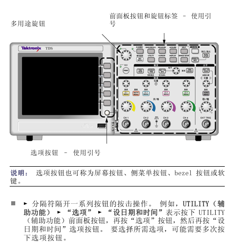
Basic Operation Guide
1. Device initialization and probe settings
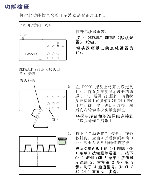
(1) Power on and self-test
After turning on, the oscilloscope automatically performs a self-test. If it displays "PASS", it is normal; If "FAIL", check the power connection or contact for repair;
Press the Default Setup button to quickly reset to factory settings (vertical coupling DC, trigger edge rise, time base 200ns/grid).
(2) Probe connection and compensation
Probe selection: It is recommended to use Tektronix specialized probes, such as P6139A (100MHz/10X) and P6249 (500MHz/10X);
Connection steps: ① Connect the BNC end of the probe to the oscilloscope channel, ② Connect the probe tip to the measured signal point, ③ Connect the reference wire to the circuit ground;
Manual compensation: ① Connect the probe to the "probe compensation" terminal (output 5V/1kHz square wave), ② Display the waveform according to AutoSet, ③ Rotate the probe compensation screw until the waveform is free of overshoot/undershoot (standard square wave);
Attenuation setting: Channel menu ->"Probe Attenuation" Set to 1X/10X, which should match the actual attenuation ratio of the probe (default 10X).
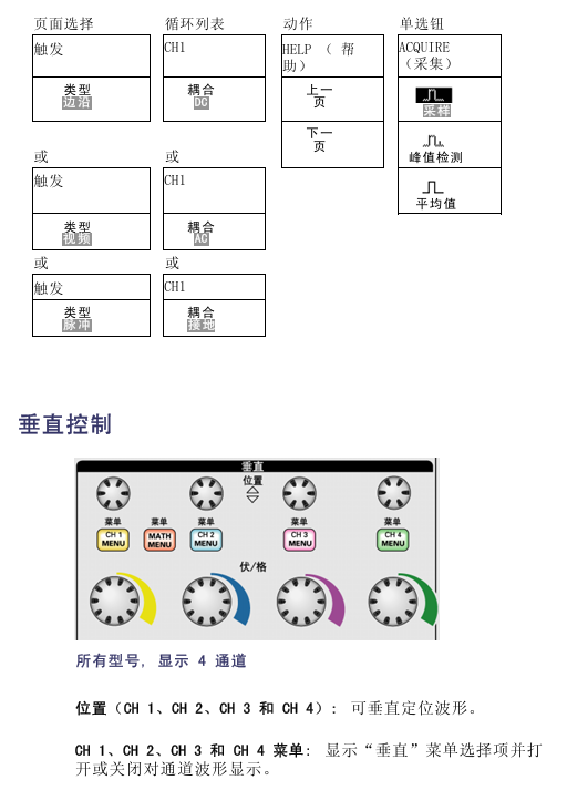
2. Core control system operation
(1) Vertical system
Coupling mode:
DC: AC/DC signal, suitable for DC bias signals (such as power supply voltage);
AC: Block DC components (attenuation<10Hz signal), suitable for AC signals (such as audio);
Grounding: Disconnect the input to determine the zero level position;
Vertical Scale: Range 2mV-10V/grid (1-2-5 sequence), adjustable through the "Vertical Scale" knob; Support "fine adjustment" mode (switch by knob), achieve non-standard stepping (such as 2.5mV/grid);
Channel control: Press the channel button (CH1/CH2, etc.) to turn on/off the channel, move the "vertical position" knob up and down to display the waveform, and support channel overlay display (press Display → "Overlay").
(2) Horizontal system
Time base range: 5ns-50s/grid (1-2-5 sequence), corresponding to the following sampling rate relationship (taking TDS3052B as an example):
Time base setting sampling rate maximum measurable frequency (Nyquist frequency)
5ns-200ns 5GS/s 2.5GHz
400ns-1μs 2.5GS/s 1.25GHz
2μs-50s 1GS/s 500MHz
Sampling mode:
Real time sampling: suitable for high-frequency signals (≤ bandwidth), directly capturing signals;
Equivalent sampling: suitable for ultra-high frequency signals (>bandwidth), reconstructing waveforms through multiple samplings;
Window function: Press Horiz Menu → "Window" to open, define waveform segments and zoom in to view, support switching between main timing and window view.
(3) Trigger system
Trigger type:
Edge trigger: Based on the rising/falling edge of the signal, the source can be selected as CH1-CH4/Ext/Ext 5x/mains power; Coupling supports DC/AC/noise suppression (reducing false triggering of high-frequency noise);
Video trigger: Supports NTSC/PAL/SECAM standards, with synchronization methods including all fields/odd fields/even fields/specified number of lines (1-525 NTSC, 1-625 PAL);
Pulse triggering: triggered by pulse width (20ns-10s), with conditions of>,<,=, ≠, suitable for abnormal pulse detection (such as burrs);
Code triggering: triggered based on logical combinations of 2-4 channels (such as CH1=high, CH2=low), supporting TTL/CMOS levels;
Key operation: Press Set to 50% to automatically set the trigger level to the midpoint of the signal peak to peak; Press Force Trigger to ignore triggering conditions and force collection.
Advanced functional applications
1. Waveform analysis and measurement
(1) Wave Inspector function
Core function: Quickly navigate long recorded waveforms (such as 1M points), avoiding the tedious operation of traditional knobs;
Operation control:
Zoom knob: The inner ring enlarges clockwise and shrinks counterclockwise, supporting separate scaling of X/Y axes;
Translation knob: Move the outer ring left and right to locate the target area;
Marking function: Set the markers (A/B/C/D) according to the markers, and display the time/amplitude difference between the markers;
Example: When analyzing the waveform of a 1M point serial bus, locate a specific data frame by scaling, pan to view the related waveforms before and after, and mark the measurement frame interval.
(2) Measurement function
Automatic measurement: Supports 29 types, with a maximum of 4 displayed at once. The commonly used types are shown in the table below:
Measurement type definition accuracy range
The frequency is calculated based on the first cycle, with units of Hz kHz MHz ± (0.01%+1 count)
Absolute difference between peak to peak maximum and minimum peak values ± (1%+2mV)
The time for the waveform to rise from 10% amplitude to 90% amplitude ± (3%+10ps)
The phase difference between the rising edges of two channel signals, in units of ± (2 °+0.1 °)
Operation steps: Press Measure → "Select Measurement" → Select Source and Type → View Real time Updated Readings;
Statistical analysis: Press "Statistics" to display the average, maximum, minimum, and standard deviation of the measured values (based on 50-1000 sampling points).
(3) FFT frequency domain analysis
Function definition: Convert time-domain (YT) signals into frequency-domain spectra, supporting 1024-1M FFT points;
Window function selection:
Window function characteristics applicable scenarios
Hanning has good frequency resolution and average amplitude accuracy. Analysis of frequency components of periodic signals
Flattop has high amplitude accuracy (± 0.1%), and its frequency resolution is generally calibrated for amplitude calibration (such as signal source output)
Rectangular without attenuation, severe spectral leakage of pulse/instantaneous signals (such as lightning waves)
Operation steps: Press Math → "FFT" → Select signal source → Set window function → Adjust frequency domain scale (Hz/grid).
2. Serial bus triggering and decoding
Supports bus types: I2C, SPI, UART (RS-232/422/485), CAN, LIN;
Trigger settings (using I2C as an example):
Press Trigger Menu ->"Type" select "Bus" ->"Bus Type" select "I2C";
Define SCLK (such as CH1), SDA (such as CH2), and set a threshold (midpoint of the waveform);
Set triggering conditions (such as address=0x50, direction=write), capture the target frame as Single;
Decoding display: Press Decode → "Enable" to overlay color labels on the time-domain waveform (address yellow, data blue, stop red); Support viewing of "event table" (displaying timestamps, types, and values), which can be exported as CSV.
3. Extreme testing and sequence acquisition
(1) Extreme testing
Function definition: Customize "templates" (such as standard waveform contours), use an oscilloscope to compare the collected waveform with the template in real-time, and mark areas that exceed the tolerance;
Application scenario: Batch production testing (such as whether the power output waveform meets the standard);
Operation steps: ① Collect standard waveforms, ② Press Limit Test → "Create Template" → Adjust tolerance (such as ± 5%), ③ Turn on "Test", display "FAIL" and mark the red area when exceeding the tolerance.
(2) Sequence collection
Function definition: Divide long signals into multiple segments (up to 100 segments) for acquisition, with each segment recording a length that is independently set (such as 10k points/segment);
Advantages: Save memory and capture intermittent burst signals (such as pulses with a 1-second interval and a duration of 10 μ s);
Operation steps: Press Acquire → "Sequence" → Set the number of segments and each segment length → Enable acquisition, and after completion, you can view the waveform segment by segment.
Data management and peripheral connectivity
1. Data storage
storage medium
Built in memory: supports 10k-1M point waveform storage, can save 50 sets of settings (. SET files);
USB flash memory: Supports ≤ 32GB, saving formats include:
Image: BMP/JPG (resolution 800 × 600);
Waveform: CSV (including time and amplitude data), TXT (Tektronix proprietary format);
Settings: SET (can directly call up applications);
Save steps: Press Save/Recall → "Save" → Select type/medium/path → Press "Confirm".
2. Peripheral connection
GPIB: Connect to PC through GPIB interface (optional module required) and use TekVISA software to achieve remote control (such as automatic testing scripts);
Ethernet: Supports LXI-C standard, connects to LAN through Ethernet cable, and accesses oscilloscope IP address through browser to achieve remote operation and data transmission;
Printer: Connect to a PictBridge compatible printer, print screen images directly by pressing Print, and support ink saving mode (white background);
PC connection: Connect the PC through a USB cable, install OpenChoice software, and achieve real-time waveform display and data export.
Safety and Maintenance
1. Safety regulations
Grounding requirements: A power cord with a grounding pin must be used, with a grounding resistance of ≤ 0.1 Ω to avoid electric shock;
Overvoltage protection: The maximum voltage of the input channel is ≤± 400V (DC+AC peak). If it exceeds this limit, a high-voltage probe should be used;
Environmental restrictions: working temperature 0-50 ℃, relative humidity 5% -90% (no condensation), altitude ≤ 3000m.
2. Troubleshooting
Troubleshooting steps for possible causes of fault phenomena
There is no display when starting up. The power supply is not connected or the power module is faulty. ① Check the power cord connection, ② Replace the power socket, ③ Contact for repair
Unstable waveform triggers improper settings/poor probe contact ① Reset the trigger level to 50% according to Set to, ② Reconnect the probe, ③ Turn on noise suppression
The measurement deviation is large, and the probe is not compensated/the attenuation setting is incorrect. ① Perform probe compensation, ② Check that the probe attenuation is consistent with the menu settings
- OMRON
- ABB
- General Electric
- EMERSON
- Honeywell
- HIMA
- ALSTOM
- Rolls-Royce
- MOTOROLA
- Rockwell
- Siemens
- Woodward
- YOKOGAWA
- FOXBORO
- KOLLMORGEN
- MOOG
- KB
- YAMAHA
- BENDER
- TEKTRONIX
- Westinghouse
- AMAT
- AB
- XYCOM
- Yaskawa
- B&R
- Schneider
- KONGSBERG
- NI
- WATLOW
- ProSoft
- SEW
- ADVANCED
- Reliance
- TRICONEX
- METSO
- MAN
- Advantest
- STUDER
- DANAHER MOTION
- Bently
- Galil
- EATON
- MOLEX
- DEIF
- B&W
- ZYGO
- Aerotech
- DANFOSS
- Beijer
- Moxa
- Rexroth
- Johnson
- WAGO
- TOSHIBA
- BMCM
- SMC
- HITACHI
- HIRSCHMANN
- Application field
- XP POWER
- CTI
- TRICON
- STOBER
- Thinklogical
- Horner Automation
- Meggitt
- Fanuc
- Baldor
- SHINKAWA
- Other Brands
- UniOP
- KUKA
- Iba
- Beckhoff
- ADLINK
-
 Basler Electric DECS-250-CN1SN1N Digital Excitation Control System
 -
 Basler Electric BE1-700 E0N2X1N Digital Protective Relay
 -
 Basler Electric SR4A-2B15B3A Static Voltage Regulator 120VAC 50/60Hz
 -
 Basler Electric 9261402111 PCB Control Board 9346000033
 -
 Basler Electric BE28053-002 Transformer BE28053002
 -
 Basler Electric BE3-25A Auto Synchronizer B1D Sync Module
 -
 Basler Electric BE3-GPR Generator Protective Relay
 -
 Basler Electric SCP-250-G-60 VAR Power Factor Controller 9 1100 00 109
 -
 Basler Electric BE3-32-1S1N1 Reverse Power Relay 277V 5A
 -
 Basler Electric ACA1300-60GM Area Scan Camera 106200-17
 -
 Basler Electric UFOV 260 A Protection Module Specs
 -
 Basler Electric BE03303001 Control Module
 -
Basler Electric BE3-GPR-P1BVSF Generator Protective Relay
-
 Basler Electric BE1-87G Solid State Protective Relay Guide
 -
 BASLER ELECTRIC BE1-60 VOLTAGE BALANCE RELAY T176884
 -
 Basler Electric BE1-32R Protective Relay
 -
 Basler Electric 9022900-103 Transformer 6-7VA 60Hz
 -
 Basler Electric BE1-59-A4E-E1K-B1S3F Overvoltage Relay
 -
 Basler Electric KR2FF-M Voltage Regulator 9 1163 00 103
 -
 Basler Electric UFOV 260 A Protective Module
 -
 Basler Electric PCB Assembly 9059701100 919620
 -
 Basler Electric SR8A2B01A3E Static Voltage Regulator
 -
 Basler Electric SSR125-12 Static Voltage Regulator 9185900102
 -
 Basler Electric SSR 63-12 Static Voltage Regulator 600VAC
 -
 Basler Electric BE1-60 Solid State Protective Relay
 -
 Basler Electric BE3-47N/27-3A4N2 Voltage Relay 9320400101
 -
 Basler Electric BE1-59 Over Voltage Relay
 -
 Basler Electric DECS100-B15 Automatic Voltage Regulator
 -
 Basler Electric PRS250 Veri-Sync Relay 9088800102
 -
Basler Electric BE25927001 Current Transformer 1:34 Amp
-
Basler Electric 9170818100 Generator Differential Relay
-
 Basler Electric BE1-59N Solid State Ground Fault Overvoltage Relay
 -
 Basler Electric 1783 DC Current Transformer Coil 1200:5A
 -
Basler Electric BE1-67 Ground Directional Overcurrent Relay
-
 Basler Electric UFOV-260A Underfrequency Overvoltage Module
 -
 Basler Electric BE10493001 Control Module
 -
Basler Electric SSR125-12 Static Voltage Regulator Guide
-
 Basler Electric BE1810/U-2 Solid State Frequency Relay Guide
 -
 Basler Electric 9105100106 UFOV-250A Protector Guide
 -
 Basler Electric MOC2199 9072300-335 Relay Module Guide
 -
 Basler Electric 9289902106 Circuit Board
 -
Basler Electric BE1-32R Protective Relay A1E E1P BOS1P
-
 Basler Electric RAL6144-16GM GigE Line Scan Camera with Lens
 -
 Basler Electric BE3-49R-5I5A1 Temperature Relay
 -
 Basler Electric BE1-32R Power Relay B3E E1R A0N1F
 -
 Basler Electric SR4A2B06B3A Static Voltage Regulator Features
 -
 Basler Electric 9121000106 Manual Voltage Control MVC Guide
 -
Basler Electric SR32A-2B15B3E Static Voltage Regulator
-
 Basler Electric SR4A2B06B3A Static Voltage Regulator Guide
 -
Basler Electric 801A193F02 Hammond Transformer Module
-
 Basler Electric BE1-24 Volts Per Hertz Relay A1E F1J D1S0F
 -
 Basler Electric AEC63-7 Analog Excitation Controller 220-277V
 -
Basler Electric BE132R Power Relay T245579
-
 Basler Electric MVC 108 Manual Voltage Control 90 37000 102
 -
 Basler Electric 9022900-103 Control Transformer 6-7VA 60Hz
 -
 Basler Electric BE1-79M Plug Adapter 9170111102
 -
 Basler Electric 9 2007 00 100 Current Boost System CBS 305
 -
 Basler Electric SR4A2B01B3A Static Voltage Regulator 120V
 -
Basler Electric BE1-32R Power Solid State Relay E2E A10 A0N0F
-
Basler Electric PRS250 Veri-Sync Relay 9088800102
-
 Basler DECS 125-15-B2C Digital Excitation Control
 -
 Basler BE 13693 002 Transformer
 -
Basler BE1-59N Ground Fault Overvoltage Relay
-
 Basler BE1-79A Reclosing Relay
 -
Basler 9-1051-00-105 Overload Protection Module
-
 Basler BE1-32R Power Relay – Directional Overcurrent Guide
 -
 Basler 9319700103 BE3-27T/59T-3A1N3 Voltage Relay
 -
Basler BE1-87G Generator Differential Relay
-
 Basler BE3-25-1D1N4 9319100106 480V Relay
 -
 Basler SR8A2B07B3A Static Voltage Regulator
 -
 Basler Electric BE4-27/59 Over/Under Voltage Relay 307-2552
 -
Basler Electric SR32A2B05B3E Static Voltage Regulator
-
Basler Electric BE1-27 A3E C3J A1N6F Solid State Protective Relay
-
 Basler Electric 9174700-100 Excitation Limiter Generator
 -
Basler Electric BE1-87G Generator Differential Relay 09833
-
 Basler Electric 9310200100 Power Supply Module
 -
 Basler Electric TIEE1CD0N07 Control Module
 -
Basler Electric BE1-59N Ground Fault Relay T214750
-
Basler Electric SR8A2B10B3AX Static Voltage Regulator 9060200126
-
 Basler Electric SSR 125-12 Voltage Regulator
 -
 Rolls Royce H1111.0204 Ship Main Controller
 -
 Basler Electric BE3-32-3AC Reverse Power Relay 9 1376 00 105
 -
Basler Electric BE3-25-1A1N4 Synch Check Relay 9319100100
-
 Basler Electric SR4A-2B15B3A Static Voltage Regulator
 -
 Basler Electric SR4A-2B15B3E Static Voltage Regulator
 -
 Basler Electric 9170818100 Solid State Protective Relay
 -
 Basler Electric AEC63-7 Analog Excitation Controller
 -
Basler Electric 17483 Auxiliary Module
-
Basler Electric BE1-59 Over Voltage Relay
-
Basler Electric 21600-101 Control Module
-
 Basler Electric KR2F Generator Voltage Regulator 9056600100
 -
Basler BE1-CDS Current Differential System
-
 Basler Electric CBS 212 Current Boost System 9 2650 00 100
 -
 Basler Electric IFM-150 Firing Circuit Chassis
 -
 Basler Electric BE1-60 Voltage Balance Relay C1F A1P D0C3F
 -
Basler Electric BE1-32R Power Relay A2E D1R A0N0F
-
Basler Electric BE1-32R Power Relay A2E D1R A0N0F
-
 Basler Electric 8650C80G01 Isolation Transducer PCB Board
 -
 ETEL EA-P2M-300-4/7.5A-0100-01 AccurET Modular 300 Servo Drive
 -
Basler Electric 87T Transformer Differential Relay
-
Basler Electric BE-6868 Power Transformer 5950007559202
-
 Basler Electric PRS250 Veri-Sync Relay 9088800102
 -
 Basler Electric SCP-250-G-60 VAR Power Factor Controller
 -
 Basler DECS-150 AVR 1NS2V1N1S Voltage Regulator
 -
Basler UFOV 260A Under Frequency Overvoltage Module
-
 Basler MOC2 199 Motor Operated Control – Overview and Setup
 -
 Basler BE3-49R-5K5A1 Temperature Relay – Complete Guide
 -
Basler BE 20035 001 Transformer – Technical Data and Installation
-
Basler BE 02727 001 Transformer – Specifications and Usage
-
 Basler BE127 Under Voltage Relay – Features and Application Guide
 -
Basler CBS377 Current Boost System – Complete Technical Guide
-
Basler BE1-87G P/N 9170818100 Differential Relay – In-Depth Specs
-
Basler BE1-87G Generator Differential Relay – Technical Overview
-
Basler Electric SR4A2B16 SVR Static Voltage Regulator – Complete Guide
-
Basler Electric 9261500101 Power Supply Module
-
 Basler Electric AEM-2020 Analog Expansion Module
 -
Basler Electric DGC-2020 Digital Genset Controller 51BRBNEAH001
-
Basler Electric BE1-59N Ground Fault Overvoltage Relay
-
Basler Electric BE1-59N-A5E-E1L-N0S1F Neutral Overvoltage Relay
-
Basler Electric MOC2499 Motor Operator Control Potentiometer 9072300430
-
 Basler Electric BE1-50/51M Overcurrent Relay
 -
 Basler Electric 9148100106 MOC3502 Solid State Relay 250VDC 0.25A
 -
 Basler Electric CBS 212 Current Boost System 9265000100
 -
Basler Electric 10493002 Control Module
-
Basler BE1-32R D3E E1R A0N1F Power Relay
-
 Basler SR8A2B15B3A Static Voltage Regulator
 -
 Basler IFM-105 Firing Circuit Chassis 9324100105
 -
Basler SR4A2B05B3A Static Voltage Regulator


