
TOSHIBA TE2 series low-voltage digital solid-state soft starter
TOSHIBA TE2 series low-voltage digital solid-state soft starter
Equipment specifications and core functions
1. Basic electrical specifications
Input voltage 208-600VAC (± 10%), 50/60Hz three-phase AC (18-48A model optional single-phase)
Output current of 18-1250A (continuous rated) is distinguished by model, for example, TE2-18-BP is 9-18A, TE2-1250-BP is 625-1250A
Starting capacity 500% rated current, 20 seconds (standard duty); 60 second (heavy duty) SCR endurance capability
Control power supply 120VAC (standard), 240VAC (optional) to be provided by the customer, VA requirements according to model: 100VA for 18-48A, 1000VA for 1250A
Protection level: Open type (to be installed inside NEMA 1/12 enclosure), anti dust/splash requires additional enclosure
Communication interface RS485 Modbus RTU baud rate 9600/19200/38400bps, address 1-247
2. Core functions and protective features
Start mode voltage ramp (VR) F010=1/3, initial voltage 0-100% (F011/F015), ramp time 1-120 seconds (F013/F017)
Current ramp (CR) F010=2/4, initial current 0-600% FLA (F012/F016), current limit 200-600% FLA (F014/F018)
Dual slope switching external contact point control (TB1-6/7), supporting VR+VR, CR+CR, VR+CR, CR+VR combination
Jog voltage 5-100% (F019), time 1-20 seconds (F020), or current 100-500% FLA (F021)
Kick Start voltage 10-100% (F022), time 0.1-2 seconds (F023), used to break through high static friction loads
Protection function: Thermal overload protection NEMA Class 5-30 (when F003 is started and F004 is running), supports manual/automatic reset (F005)
Phase protection phase loss (current<12% CT value), phase imbalance (5-30%, F040), phase rotation (ABC/ACB, F098)
Voltage protection overvoltage 1-10% (F032), undervoltage 1-20% (F034 startup/F036 operation), voltage imbalance 1-30% (F030)
Current protection overcurrent 100-300% FLA (F042), undercurrent 10-90% FLA (F044, load loss detection), grounding fault 5-90% CT value (F046)
Mechanical protection start interval lock (1-60 minutes, F050), hourly start limit (1-10 times, F049), reverse lock (1-60 minutes, F048)
Installation and wiring
1. Installation requirements
Environmental temperature conditions: 0-40 ° C (working), -5-40 ° C (storage); Humidity: 5-95% RH (no condensation) Avoid dust, corrosive gases, and vibration (<0.5G)
The installation spacing should be ≥ 25mm (1 inch) on both sides and ≥ 100mm (4 inches) on both sides to ensure heat dissipation. Multiple units should be placed side by side with gaps left
Cooling direction: The ribs of the cooling fins are vertically installed to assist with fan cooling, ensuring smooth airflow
The shell requirement is that open models should be installed in NEMA 1 (indoor) or NEMA 12 (dustproof and splash proof). The size of the inner and outer shells of the shell should meet the requirements of heat dissipation: for example, the shell volume of 18-481 should be ≥ 0.05m ³
2. Wiring configuration (key terminals)
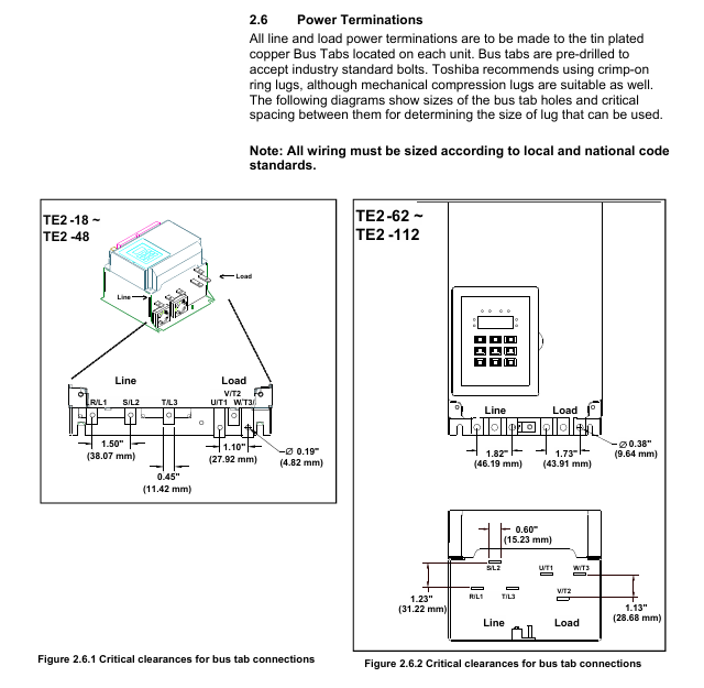
(1) Power wiring (main circuit)
L1/L2/L3 (R/S/T) main power input three-phase 208-600VAC, requires circuit breaker/isolation switch TE2-18-BP: 10AWG, torque 35in lbs (M5 bolt)
T1/T2/T3 (U/V/W) motor output is connected to a three-phase motor, and reverse input/output TE2-1250-BP: 4 × 500kCMIL, torque TBD is strictly prohibited
The grounding terminal equipment shall be grounded according to NEC specifications, with a wire diameter not less than 1/2 of the phase wire. For example, a 10AWG phase wire shall be paired with an 8AWG grounding wire
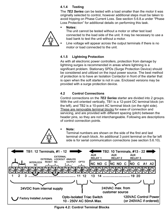
(2) Control wiring (TB1 DC 24V, TB2 AC 120/240V)
TB1 (DC 24V) 1-3 3-wire control (Start/Stop) 1 connected to Start (NO), 2 connected to the common terminal, 3 connected to Stop (NC)
External interlock (NC) 4-5 connected to low oil level/high temperature switch, factory jumper needs to be removed
6-7 dual slope switch to external contacts, close and activate slope 2
7-8 Jog: Connect to external contacts, close to activate Jog (requires Start command)
9-10 analog output (4-20mA) connected to PLC/instrument, monitoring current/voltage/thermal capacity (F108 setting)
11-12 fault output (optocoupler Triac) connected to PLC, conducting in case of fault (240VAC/50mA max)
TB2 (AC control power supply) 21-22 (A1-A2) control power supply input 120VAC (standard), requires 1A fuse connection
13-20 auxiliary relay outputs 3 relays: 2 SPDT (13-18), 1 SPST (19-20), 240VAC/5A
Parameter programming
1. Core mandatory parameters
The rated current (FLA) of F001 motor must be set to the FLA on the motor nameplate, otherwise the soft starter will not operate. Range: 50-100%. The maximum current of the soft starter is 9-18A, such as TE2-18-BP
The service factor (SF) of F002 motor is set according to the motor nameplate, affecting the FLA upper limit 1.0 range of 1.00-1.30. If SF ↑, F001 can be set within the range ↓
F003/F004 Start/Run Overload Level NEMA Class 5-30, Match Motor Overload Capacity 10 (Class 10) Set High Level (e.g. Class 20) during Start to Avoid False Alarm
F010 Slope Type Selection: Choose Voltage/Current Slope and Double Slope Combination 1 (VR1+VR2). For heavy loads, choose CR, and for light loads, choose VR
F014/F018 maximum current limit limits the starting current and protects the power grid and motor by 350%. When the FLA power grid capacity is small, set it low (such as 250%), and when overloaded, set it high (such as 500%)
2. Programming operation process
Enter programming mode: In the status display mode (default display of A-phase current), press the 【 Fn 】 key to enter the F001 parameter interface.
Adjust parameters:
Press the ←/→ key to select the digit to be modified (flashing);
Press the 【 ↑/↓ 】 keys to adjust the value (long press for 2 seconds to start automatic stepping);
Press the 【 ENT 】 key to save and display 'End' for confirmation.
Password protection:
Set F070 to a non-zero value (1-999) to enable the password, and enter the password for the next modification;
If you forget your password, please contact Toshiba customer service to restore the factory settings (F071=2) without clearing the password.
Communication programming: Connect PLC/upper computer through RS485 Modbus and modify parameter registers (such as register address 0x0001 corresponding to F001).
Startup and troubleshooting
1. Initiation process and inspection
Step operation content Key checkpoints
1. Confirm that the wiring of the main power supply, motor, and control power supply is correct, the grounding is reliable, and there is no looseness
The required parameters F001 (FLA), F002 (SF), and F010 (slope type) for parameter settings have been correctly configured
3. Power on test: Connect the control power supply, the "Power On" LED lights up and displays 【 0000. 】 (phase A has no current)
Press the Start button to start the test, the motor accelerates according to the set slope, the "At Speed" LED lights up (the motor reaches full speed), and the bypass contactor is closed
5. If the machine stops during startup, check the fault code (such as "oLA"=overload, increase F003)
2. Common faults and troubleshooting
Troubleshooting steps for fault codes and causes
NFLA motor FLA not set (F001=0) 1. Enter programming mode; 2. Let F001 be the motor nameplate FLA; 3. Restart after saving
1. Check if the main power supply L1/L2/L3 is out of phase during PLc operation; 2. Check if the motor wiring T1/T2/T3 is loose; 3. Confirm that the phase loss protection (F101) has not been mistakenly enabled
Overload during oLA startup: 1. Check if F003 (startup overload level) is too small (if set to Class 5), it can be increased to Class 15; 2. Check if the load is too heavy, reduce the starting load or increase the current limit (F014)
SSd SCR short circuit or no load 1. Disconnect the power supply and measure whether the SCR (L1-T1, L2-T2, L3-T3) is short circuited; 2. Confirm that the motor is connected (no load will report this fault)
Ground fault during GFc operation: 1. Check if the motor winding is grounded; 2. Check if the cable insulation is damaged; 3. Adjust the grounding fault threshold (F046) or delay (F047)
3. Fault recording and reset
Fault record: F085-F093 stores the last 3 faults, including fault codes (F085/F088/F091), timestamps (F086/F089/F092), and date stamps (F087/F090/F093).
Reset method:
Manual reset: After troubleshooting, press the [Reset] button. If there is an overload fault, wait for the motor to cool down (heat capacity H ≥ F059);
Automatic reset: F052 selects the fault type (such as 4=phase loss), F053 sets the reset frequency (1-10 times), 1 minute/time;
Remote reset: Disconnect the control power and reconnect it (applicable to scenarios without Reset button).
Maintenance and Appendix
1. Regular maintenance
Maintenance project cycle operation requirements
Clean the heat sink every 3 months (in dusty environments) and blow it with 80-100psi dry compressed air. Do not use chemicals/metal brushes
Check the power/control terminals for looseness every 6 months and tighten them again (according to torque requirements)
Fan inspection: Every year, listen to the running noise of the fan. If there is any abnormality, replace it (with a lifespan of 3 years/30000 hours)
Capacitor inspection: The main circuit capacitor has a lifespan of 10 years/73000h every 5 years. If it exceeds the lifespan, it is recommended to replace it
Backup parameters every year through BSD Configurator to avoid loss
2. Important Appendix Content
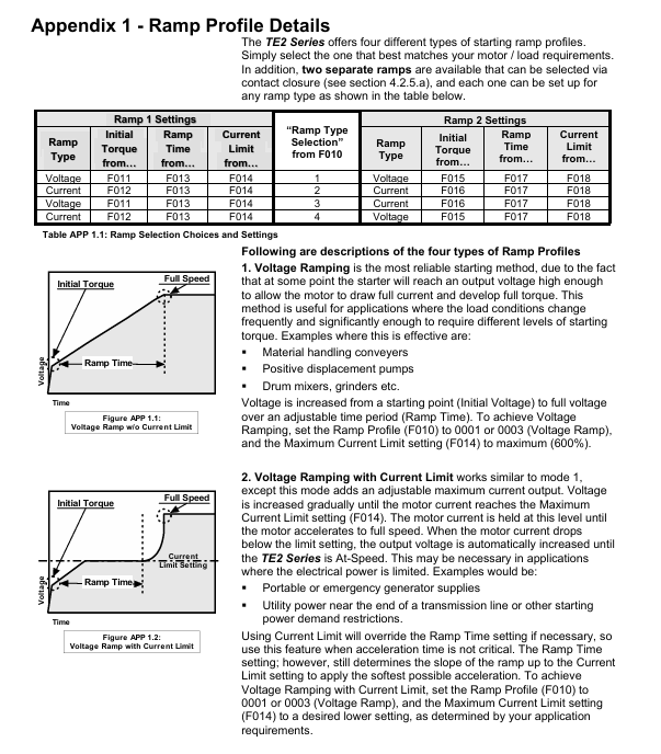
Appendix 1 (Slope Details): Detailed explanation of the differences in VR/CR slope curves. It is recommended to use VR for centrifugal pumps and CR for long conveyor belts.
Appendix 2 (Pump Flex Deceleration): Used for soft stop of pumps to avoid water hammer effect, it is necessary to set the starting deceleration voltage (F025), stopping voltage (F026), and deceleration time (F027).
Appendix 3 (Password Protection): The process for handling lost passwords requires contacting Toshiba customer service for unlocking methods.
Appendix 4 (External Overload): When multiple motors are controlled or started by bypass, an external overload relay (OLR) is required. The wiring example is shown in document APP4.2.
Appendix 5 (Parameter Record): A blank table is used to record the parameters modified by the user for easy maintenance and traceability.
Key issue
Question 1: What are the core startup modes of the TE2 series soft starter? What scenarios are different modes applicable to? How to start voltage ramp (VR) by configuring parameters?
Answer:
Core startup mode and applicable scenarios:
Applicable scenarios for the principle of startup mode
Voltage ramp (VR) output voltage increases linearly from the initial value (0-100%) to the rated voltage within a set time (1-120 seconds), and the current automatically adjusts with the load for light/medium loads, such as centrifugal fans, small water pumps, and conveyor belts (with stable load resistance)
The output current of the current ramp (CR) increases linearly from the initial value (0-600% FLA) to the current limit value (200-600% FLA) according to the set time. The voltage is adaptively adjusted for heavy/high static friction loads, such as crushers, presses, and deep well water (to break through static friction and avoid sudden current rise during startup)
Dual slope switching is achieved through external contacts (TB1-6/7) to switch between two slope modes (such as VR+CR) in scenarios with large load fluctuations, such as conveyor belts with empty/full load switching (slope 1 for empty load, slope 2 for full load)
Output short-term high voltage (10-100%, 0.1-2 seconds) before Kick Start, breaking through high static friction freezing pumps and stuck mechanical transmission systems (requiring instant high torque)
Parameter configuration steps for voltage ramp (VR) startup:
Enter programming mode: Press the Fn key on the status display (default A-phase current) to enter the F001 interface;
Set slope type: Press the 【 ←/→ 】 key to switch to F010, set it to "1" (Ramp1=VR, Ramp2=VR) or "3" (Ramp1=VR, Ramp2=CR), press 【 ENT 】 to save;
Configure Ramp1 parameters (enabled by default):
F011 (initial voltage): set to 10-30% (e.g. 20%, ensure that the motor can start without impact);
F013 (acceleration time): set to 5-20 seconds (such as 10 seconds, adjusted according to the load, the water pump can be set short, and the conveyor belt can be set long);
F014 (current limit): Set to 300-400% FLA (e.g. 350% to avoid grid overload);
(Optional) Configure Ramp2 parameters: If dual ramp is required, set F015 (Ramp2 initial voltage), F017 (Ramp2 acceleration time), F018 (Ramp2 current limit);
Exit programming mode: Press the Fn key to return to the status display and start the motor to verify the slope effect.
Question 2: What motor protection functions are built into the TE2 series soft starter? How to configure thermal overload protection to match motor characteristics? How to troubleshoot when reporting an "oLA" (overload during startup) fault?
Answer:
Built in motor protection function:
Key parameters for specific functions of protection categories
Thermal overload protection simulates the thermal characteristics of the motor (I ² t curve) to prevent motor overheating. F003 (starting overload level), F004 (running overload level), F005 (reset mode)
Phase protection phase loss (current<12% CT value), phase imbalance (5-30%), phase rotation (ABC/ACB) F100 (phase loss delay at stop), F101 (phase loss delay during operation), F098 (phase rotation)
Voltage protection overvoltage (1-10% rated voltage), undervoltage (1-20%, divided into start-up/operation), voltage imbalance (1-30%) F032 (overvoltage threshold), F034 (start-up undervoltage), F036 (operating undervoltage), F030 (voltage imbalance)
Current protection overcurrent (100-300% FLA, electronic shear pin), undercurrent (10-90% FLA, load loss), ground fault (5-90% CT value) F042 (overcurrent threshold), F044 (undercurrent threshold), F046 (ground fault threshold)
Mechanical protection start interval lock (1-60 minutes), hourly start times (1-10 times), reverse lock (1-60 minutes) F050 (start interval), F049 (hourly start times), F048 (reverse lock)
Steps for configuring thermal overload protection:
Determine motor parameters: Obtain FLA (rated current) and NEMA overload level (such as Class 15) from the motor nameplate;
Configure basic parameters:
F001 (motor FLA): Set as the motor nameplate FLA (such as 10A), it must be accurate, otherwise the protection will fail;
F002 (Service Factor SF): Set according to the motor nameplate (such as 1.15), if SF ↑, F001 can be set with an upper limit ↓;
Configure overload level:
F003 (Starting Overload Level): Set as the overload level when the motor starts (such as Class 20, higher than the operating level to avoid starting false alarms);
F004 (Operational Overload Level): Set as the overload level during motor operation (such as Class 15, matched with motor thermal tolerance);
Configuration reset method: Set F005 to "0" (manual reset, press the reset button) or "1" (automatic reset, 1-10 attempts, caution required for 2-wire control).
Troubleshooting steps for "oLA" (overload during startup):
Confirm load status: Check if the motor is stuck, if the load is too heavy (such as if the conveyor belt is stuck or there are foreign objects in the pump), and eliminate mechanical faults;
Check parameter configuration:
Check if F001 (FLA) is lower than the actual FLA of the motor (e.g. motor FLA=15A, F001=10A, protection threshold too low), and it needs to be corrected to 15A;
Check F003 (startup overload level): whether it is too small (such as Class 5, which causes false alarms due to short startup time), it can be increased to Class 15-20;
Check F014 (current limit): if it is too low (such as 200% FLA, not enough to drive the load), it can be increased to 350-400% FLA;
Check the power supply and wiring:
Measure the main power supply voltage: whether it is lower than the rated value (such as the actual 180V of the 208V system, causing an increase in starting current), and repair the power supply is required;
Check the motor wiring: T1/T2/T3 for looseness (high contact resistance, sudden increase in current), re tighten the terminals;
Verification and adjustment: After troubleshooting, restart and observe the current curve. If the overload still persists, evaluate whether the capacity of the soft starter matches the motor (e.g. motor 100HP, soft starter only 75HP, need to be replaced with a larger capacity model).
Question 3: What are the types of wiring for TE2 series soft starters? How to configure 3-wire control and analog output (4-20mA) wiring? What are the functions and wiring precautions of bypass contactors?
Answer:
Wiring classification: TE2 series wiring is divided into three categories according to function: power wiring (main circuit), control wiring (signal circuit), and communication wiring (optional):
Power wiring: Connect the main power supply (L1/L2/L3) and the motor (T1/T2/T3), carry high currents, and match the wire diameter and torque according to the model;
Control wiring: including 3-wire/2-wire start control, interlock signal, jog signal, analog output, fault output, etc., using low voltage (DC 24V/AC 120V);
Communication wiring: RS485 Modbus communication, used for remote monitoring and parameter configuration of upper computer (PLC/touch screen), using shielded twisted pair cables.
Key control wiring configuration:
(1) 3-wire control (Start/Stop button) wiring:
Terminal selection: Terminals 1, 2, and 3 of TB1 (DC 24V terminal block);
Wiring logic:
Terminal 1: One end connected to the Start button (normally open NO contact);
Terminal 2: Connect the other end of the Start button and one end of the Stop button (normally closed NC contact);
Terminal 3: Connect the other end of the Stop button to form a series circuit of "Start NO+Stop NC";
Attention: TB1 has a built-in 24V DC power supply and does not require an external power supply; The Stop button needs to have normally closed contacts to ensure that the motor stops when the power is cut off.
(2) Analog output (4-20mA) wiring:
Function: Output signals such as motor current, voltage, and thermal capacity for PLC or instrument monitoring;
Terminal selection: Terminal 9 (signal+) and Terminal 10 (signal -) of TB1;
Wiring steps:
Connect TB1-9/10 to the analog input module (4-20mA channel) of the PLC using shielded twisted pair cables;
Programming parameter F108: Select monitoring signal (e.g. "1"=A-phase current, "12"=thermal capacity);
Programming parameters F109 (corresponding value of 4mA) and F110 (corresponding value of 20mA): If monitoring phase A current from 0-200A, set F109=0 and F110=200;
Attention: Single ended grounding of shielding layer (soft starter side) to avoid interference; The distance between the analog line and the power line is ≥ 10cm to reduce electromagnetic interference.
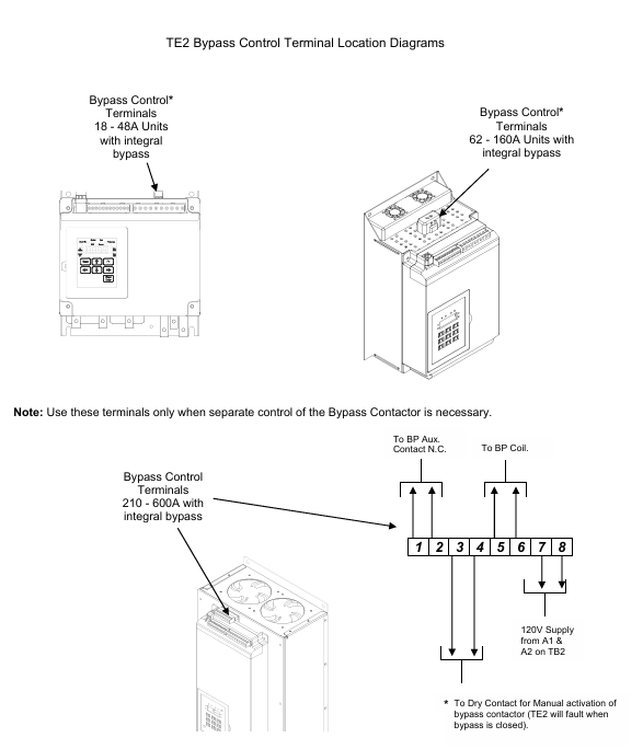
Function and wiring precautions of bypass contactor:
Function:
After the soft starter completes the start-up (when the motor reaches full speed and the "At Speed" LED lights up), the bypass contactor is closed to short-circuit the SCR and prevent it from overheating during long-term operation, thereby extending its lifespan;
When there is a fault (such as SCR short circuit), the bypass contactor will disconnect and cut off the motor power supply;
Some models (BP series) support "emergency bypass start". When the soft starter fails, the motor can be directly started by controlling the bypass contactor through external contacts (requiring external overload protection).
Wiring precautions:
Built in bypass contactor (BP series): The factory has completed internal wiring, no on-site wiring is required, only ensure that the control power supply (A1-A2, TB2-21/22) is normal;
Emergency bypass wiring (optional):
Terminal selection: B1 (coil+) and B2 (coil -) terminals of TB4 (only available in BP series);
Wiring requirements: External normally closed contacts (such as emergency buttons), directly engage the bypass contactor when closed; External overload relay (OLR) contacts need to be connected in series to avoid unprotected operation of the motor;
Capacity matching: The rated current of the bypass contactor should be ≥ the rated current of the motor. In case of emergency bypass, the selection should be based on "full voltage starting" (e.g. motor 100A, contactor 125A);
Interlocking logic: Before closing the bypass contactor, it is necessary to confirm that the motor has reached full speed to avoid a sudden increase in current caused by the bypass at half speed (the soft starter has a built-in "At Speed" detection, which automatically controls the contactor).
- OMRON
- ABB
- General Electric
- EMERSON
- Honeywell
- HIMA
- ALSTOM
- Rolls-Royce
- MOTOROLA
- Rockwell
- Siemens
- Woodward
- YOKOGAWA
- FOXBORO
- KOLLMORGEN
- MOOG
- KB
- YAMAHA
- BENDER
- TEKTRONIX
- Westinghouse
- AMAT
- AB
- XYCOM
- Yaskawa
- B&R
- Schneider
- KONGSBERG
- NI
- WATLOW
- ProSoft
- SEW
- ADVANCED
- Reliance
- TRICONEX
- METSO
- MAN
- Advantest
- STUDER
- DANAHER MOTION
- Bently
- Galil
- EATON
- MOLEX
- DEIF
- B&W
- ZYGO
- Aerotech
- DANFOSS
- Beijer
- Moxa
- Rexroth
- Johnson
- WAGO
- TOSHIBA
- BMCM
- SMC
- HITACHI
- HIRSCHMANN
- Application field
- XP POWER
- CTI
- TRICON
- STOBER
- Thinklogical
- Horner Automation
- Meggitt
- Fanuc
- Baldor
- SHINKAWA
- Other Brands
- UniOP
- KUKA
- Iba
- Beckhoff
-
 Basler SR32A2B05B3E Static Voltage Regulator
 -
 Basler Electric BE1-59N Ground Fault Overvoltage Relay
 -
 Basler Electric 9110000113 Excitation Module
 -
 Basler Electric 90-72300-114 Control Accessory
 -
 Basler Electric PRS-250 Protection Relay System
 -
Basler Electric BE1-50/51M-109 Overcurrent Relay
-
 Basler Electric SR4A1B10B3E Static Voltage Regulator
 -
 Basler Electric CBS 212 Current Boost System
 -
Basler Electric SR32A2B05B3E Static Voltage Regulator
-
Basler Electric MOC2207 Motor Operated Potentiometer
-
 Basler Electric SR4A1B05A3E Static Voltage Regulator
 -
 Basler Electric BE1-32R Power Relay B2EE1PA0N1F
 -
Basler BEI-81 Underfrequency Relay
-
Basler CBS 212A Current Boost System
-
 Basler SSR 63-12 Static Voltage Regulator
 -
 Basler DGC-2020 Digital Genset Controller
 -
Basler BE1-32 Reverse Power Relay
-
 Basler BE1-50/51B-207 Overcurrent Relay
 -
 Basler BE1-951 Overcurrent Protection System
 -
 Basler 9073800-103 Power Supply
 -
 Basler SCA1300-32FC CCD Camera
 -
Basler 9073800-103 Power Supply
-
Basler SCA1300-32FC CCD Camera
-
 Basler L304KC Protective Relay
 -
 Basler BE3-25-1S1N4 Time Overcurrent Relay
 -
 Basler 9032300113 Excitation Support System
 -
 Basler BE1-59N Ground Overvoltage Relay
 -
 Basler MVC-300 Manual Voltage Control Unit
 -
 Basler MOC2102 Potentiometer
 -
 Basler BE1-87G Generator Differential Relay
 -
 Basler Electric DECS-200 Digital Excitation Control System
 -
Basler Electric DECS 125-15-B2C5 Digital Excitation System
-
 Basler Electric PLA2400-12GM Power Supply
 -
 Basler Electric BE1-50/51B-235 Overcurrent Relay
 -
Basler Electric BE1-27/59 Undervoltage Overvoltage Relay
-
 Basler Electric CEM-2020 Contact Expansion Module
 -
 Basler Electric BE1-32R Solid State Power Relay
 -
 Basler Electric BE1-700 Digital Generator Management Relay
 -
Basler Electric BE1-59N Ground Fault Overvoltage Relay
-
 Basler Electric BE10493002 Protection Module
 -
 Basler Electric BEI-79A1AA5CA3M1F Digital Annunciator
 -
 Basler Electric SSR 32-12 Static Voltage Regulator
 -
Basler Electric BE1-CDS240 Current Differential System
-
Basler Electric BE1-67 Directional Overcurrent Relay
-
 Basler Electric 9121000106 DECS-100 Voltage Controller
 -
Basler Electric BEI-871 Interface Module
-
 Basler Electric 8650C72 Exciter Control Module
 -
 Basler Electric RDP-110-S1 Generator Annunciator
 -
Basler Electric BE1-32O/U Directional Power Relay
-
 Basler Electric BE2000E AVR Voltage Regulator
 -
BASLER ELECTRIC BE1-50F2EA1PA0N0F Instantaneous Overcurrent Relay
-
BASLER ELECTRIC BE1-81T1EE1WA0N1F Underfrequency Relay
-
Basler BE1-67 Directional Overcurrent Relay
-
Basler BE1-25/79TR Reclosing Relay
-
Basler CEM-2020 Contact Expansion Module
-
Basler BE1-11 Overcurrent Protection Relay
-
 Basler BE1-GPS Generator Protective Relay
 -
 BASLER ELECTRIC MVC-300 MANUAL VOLTAGE CONTROL UNIT 9121000106
 -
 Basler Electric KR2FF Voltage Regulator 9 1163 00 109
 -
 BASLER ELECTRIC BE1-87G-G1E-A1K-A0N0F Generator Differential Relay
 -
 Basler BE1-47NE3EA1PA0N2F Phase Sequence Relay
 -
 Basler BE1-81-T1E-E1C-B0N1F Frequency Relay
 -
Basler DECS125-15 Excitation Control
-
Basler BE1-25 Sync-Check Relay
-
 Basler BE1-50/51B Overcurrent Relay
 -
Basler BE1-40Q Loss of Excitation Relay
-
 Basler BE1-50/51M-104 Overcurrent Relay
 -
Basler SSE-N 250-9 KW Shunt Exciter Assembly
-
Basler BE1-87T Transformer Differential Relay
-
 Basler BE1-60 Solid State Protective Relay
 -
Basler DECS125-15 Excitation Control System
-
Basler SR4A-2B15B3A Static Voltage Regulator
-
 Basler BE150BF Overcurrent Relay
 -
 BASLER ELECTRIC BE1A1HF1JD1S2F Overcurrent Relay
 -
Basler BE1-81O Under/Over Frequency Relay
-
 Basler EDM-200 Exciter Diode Monitor
 -
 Basler DECS125-15-B2C5 Excitation Control
 -
 Basler 9261402100 PCB Board
 -
Basler 9252000107 Overcurrent Relay
-
Basler BE1-87T Solid State Protective Relay
-
Basler Electric Phase Directional Overcurrent Relay BE1-Z2JA0N2F
-
 Basler SSR125-12 Static Voltage Regulator
 -
 Basler Electric KR7F VOLTAGE REGULATOR 9116200100
 -
BASLER ELECTRIC BE1-59N-A8E-E1L-N0S1F Ground Overvoltage Relay
-
 Basler SR8A2B06B3A Static Voltage Regulator
 -
BASLER ELECTRIC BE1-81O/UT3EE1KA7N1F Under/Over Frequency Relay
-
 Basler MOC2107 Output Module
 -
 Basler 9125600102 Control Module
 -
 BASLER ELECTRIC BE1-81T1EE1EA2N0F
 -
 Basler BE3-25A Time Overcurrent Relay
 -
Basler Electric CBS 212 Current Boost System 9 2650 00 100 120/240 VAC 50/60Hz
-
Basler Electric BE1-27 Under Voltage Relay A3EC1JA0N5F
-
 Basler BE1-32R Power Relay B2EE1PA0N1F
 -
 Basler DECS100-B15 Automatic Voltage Regulator
 -
 Basler SR8A-2B15B3A Static Voltage Regulator
 -
 Basler AVC63-4 Analog Voltage Regulator
 -
 Basler UFOV 260 A Overvoltage Module
 -
 Basler SR4A-2B16B3A Static Voltage Regulator
 -
Basler SR4A-2B16B3E Static Voltage Regulator
-
Basler SCA1300-32GM CCD Camera
-
 Basler BE34062001 G18 Transformer
 -
Basler BE1-87T Transformer Differential Relay
-
 Basler 9 2849 00 101 DECS Power Module
 -
 Basler RAL6144-16GM Line Scan Camera
 -
 Basler 9269101107 Voltage Regulator Board
 -
Basler BE1-851 Overcurrent Relay
-
Basler SR32A-2B13B3E Static Voltage Regulator
-
 Basler 9 2007 00 100 Current Boost System CBS 305
 -
Basler DECS-100-B11 Automatic Voltage Regulator
-
 Basler BE127 Under Voltage Relay
 -
 Basler 3300C03B1028-G01 Spike Suppressor
 -
Basler SSR 125-12 Static Voltage Regulator
-
Basler SCA1300-32GM CCD Camera Lens Enclosure
-
 Basler BE32965001 Transformer Timer Kit
 -
Basler D90 96801 100 PCB Card
-
 Basler BE1-81-T1E-E1C-A0N1F / 9106400 Underfrequency Relay
 -
 Pro-Face Basler AGP3600-T1-D24 HMI Touch
 -
Basler SR4A2B10B1A Static Voltage Regulator
-
Basler SR8A2B05B3A Static Voltage Regulator
-
Basler BE1-25 Time Overcurrent Relay M1FA6PA4S0F
-
Basler SR4A2B05B3E Static Voltage Regulator
-
 Basler DECS-200-2L Digital Excitation Control
 -
 Basler BE303280001 Control Transformer
 -
Basler 9262103004 Voltage Regulator Board For Basler DECS-400
-
 Basler ICRM-7 Inrush Current Reduction Module
 -
Basler BE1-32R Power Relay
-
BASLER ELECTRIC KR4F VOLTAGE REGULATOR 9042600100 600V 50/60Hz
-
Basler 9222600101 Power Module


