TOSHIBA TE2 series low-voltage digital solid-state soft starter
TOSHIBA TE2 series low-voltage digital solid-state soft starter
Equipment specifications and core functions
1. Basic electrical specifications
Input voltage 208-600VAC (± 10%), 50/60Hz three-phase AC (18-48A model optional single-phase)
Output current of 18-1250A (continuous rated) is distinguished by model, for example, TE2-18-BP is 9-18A, TE2-1250-BP is 625-1250A
Starting capacity 500% rated current, 20 seconds (standard duty); 60 second (heavy duty) SCR endurance capability
Control power supply 120VAC (standard), 240VAC (optional) to be provided by the customer, VA requirements according to model: 100VA for 18-48A, 1000VA for 1250A
Protection level: Open type (to be installed inside NEMA 1/12 enclosure), anti dust/splash requires additional enclosure
Communication interface RS485 Modbus RTU baud rate 9600/19200/38400bps, address 1-247
2. Core functions and protective features
Start mode voltage ramp (VR) F010=1/3, initial voltage 0-100% (F011/F015), ramp time 1-120 seconds (F013/F017)
Current ramp (CR) F010=2/4, initial current 0-600% FLA (F012/F016), current limit 200-600% FLA (F014/F018)
Dual slope switching external contact point control (TB1-6/7), supporting VR+VR, CR+CR, VR+CR, CR+VR combination
Jog voltage 5-100% (F019), time 1-20 seconds (F020), or current 100-500% FLA (F021)
Kick Start voltage 10-100% (F022), time 0.1-2 seconds (F023), used to break through high static friction loads
Protection function: Thermal overload protection NEMA Class 5-30 (when F003 is started and F004 is running), supports manual/automatic reset (F005)
Phase protection phase loss (current<12% CT value), phase imbalance (5-30%, F040), phase rotation (ABC/ACB, F098)
Voltage protection overvoltage 1-10% (F032), undervoltage 1-20% (F034 startup/F036 operation), voltage imbalance 1-30% (F030)
Current protection overcurrent 100-300% FLA (F042), undercurrent 10-90% FLA (F044, load loss detection), grounding fault 5-90% CT value (F046)
Mechanical protection start interval lock (1-60 minutes, F050), hourly start limit (1-10 times, F049), reverse lock (1-60 minutes, F048)

Installation and wiring
1. Installation requirements
Environmental temperature conditions: 0-40 ° C (working), -5-40 ° C (storage); Humidity: 5-95% RH (no condensation) Avoid dust, corrosive gases, and vibration (<0.5G)
The installation spacing should be ≥ 25mm (1 inch) on both sides and ≥ 100mm (4 inches) on both sides to ensure heat dissipation. Multiple units should be placed side by side with gaps left
Cooling direction: The ribs of the cooling fins are vertically installed to assist with fan cooling, ensuring smooth airflow
The shell requirement is that open models should be installed in NEMA 1 (indoor) or NEMA 12 (dustproof and splash proof). The size of the inner and outer shells of the shell should meet the requirements of heat dissipation: for example, the shell volume of 18-481 should be ≥ 0.05m ³
2. Wiring configuration (key terminals)
(1) Power wiring (main circuit)
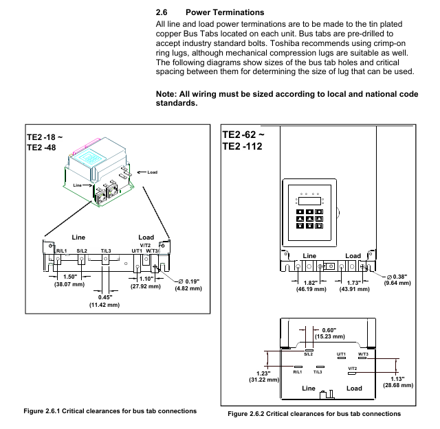
L1/L2/L3 (R/S/T) main power input three-phase 208-600VAC, requires circuit breaker/isolation switch TE2-18-BP: 10AWG, torque 35in lbs (M5 bolt)
T1/T2/T3 (U/V/W) motor output is connected to a three-phase motor, and reverse input/output TE2-1250-BP: 4 × 500kCMIL, torque TBD is strictly prohibited
The grounding terminal equipment shall be grounded according to NEC specifications, with a wire diameter not less than 1/2 of the phase wire. For example, a 10AWG phase wire shall be paired with an 8AWG grounding wire
(2) Control wiring (TB1 DC 24V, TB2 AC 120/240V)
TB1 (DC 24V) 1-3 3-wire control (Start/Stop) 1 connected to Start (NO), 2 connected to the common terminal, 3 connected to Stop (NC)
External interlock (NC) 4-5 connected to low oil level/high temperature switch, factory jumper needs to be removed
6-7 dual slope switch to external contacts, close and activate slope 2
7-8 Jog: Connect to external contacts, close to activate Jog (requires Start command)
9-10 analog output (4-20mA) connected to PLC/instrument, monitoring current/voltage/thermal capacity (F108 setting)
11-12 fault output (optocoupler Triac) connected to PLC, conducting in case of fault (240VAC/50mA max)
TB2 (AC control power supply) 21-22 (A1-A2) control power supply input 120VAC (standard), requires 1A fuse connection
13-20 auxiliary relay outputs 3 relays: 2 SPDT (13-18), 1 SPST (19-20), 240VAC/5A
Parameter programming
1. Core mandatory parameters
The rated current (FLA) of F001 motor must be set to the FLA on the motor nameplate, otherwise the soft starter will not operate. Range: 50-100%. The maximum current of the soft starter is 9-18A, such as TE2-18-BP
The service factor (SF) of F002 motor is set according to the motor nameplate, affecting the FLA upper limit 1.0 range of 1.00-1.30. If SF ↑, F001 can be set within the range ↓
F003/F004 Start/Run Overload Level NEMA Class 5-30, Match Motor Overload Capacity 10 (Class 10) Set High Level (e.g. Class 20) during Start to Avoid False Alarm
F010 Slope Type Selection: Choose Voltage/Current Slope and Double Slope Combination 1 (VR1+VR2). For heavy loads, choose CR, and for light loads, choose VR
F014/F018 maximum current limit limits the starting current and protects the power grid and motor by 350%. When the FLA power grid capacity is small, set it low (such as 250%), and when overloaded, set it high (such as 500%)
- ABB
- General Electric
- EMERSON
- Honeywell
- HIMA
- ALSTOM
- Rolls-Royce
- MOTOROLA
- Rockwell
- Siemens
- Woodward
- YOKOGAWA
- FOXBORO
- KOLLMORGEN
- MOOG
- KB
- YAMAHA
- BENDER
- TEKTRONIX
- Westinghouse
- AMAT
- AB
- XYCOM
- Yaskawa
- B&R
- Schneider
- Kongsberg
- NI
- WATLOW
- ProSoft
- SEW
- ADVANCED
- Reliance
- TRICONEX
- METSO
- MAN
- Advantest
- STUDER
- KONGSBERG
- DANAHER MOTION
- Bently
- Galil
- EATON
- MOLEX
- DEIF
- B&W
- ZYGO
- Aerotech
- DANFOSS
- Beijer
- Moxa
- Rexroth
- Johnson
- WAGO
- TOSHIBA
- BMCM
- SMC
- HITACHI
- HIRSCHMANN
- Application field
- XP POWER
- CTI
- TRICON
- STOBER
- Thinklogical
- Horner Automation
- Meggitt
- Fanuc
- Baldor
- SHINKAWA
- Other Brands


