
TEKTRONIX THDP0100/0200 and TMDP0200 series high-voltage differential probes
TEKTRONIX THDP0100/0200 and TMDP0200 series high-voltage differential probes
Compliance Information and Environmental Requirements
1. EMC (Electromagnetic Compatibility) compliance
Core Directive: Complies with the requirements of EU Directive 2004/108/EC.
Key criteria:
Emission standards: EN 61326-1:2006, EN 61326-2-1:2006, CISPR 11:2003 (Group A, Radiation and Conducted Emissions);
Immunity standard: IEC 61000-4 series (electrostatic discharge, radio frequency electromagnetic field, electrical fast transient, power surge, voltage sag, etc.);
Power standards: EN 61000-3-2:2006 (harmonic emission), EN 61000-3-3:1995 (voltage fluctuation and flicker).
Special note:
Only for non residential use, residential use may generate electromagnetic interference;
When connecting the tested object, it may exceed the standard emission limit, and high-quality shielded interface cables should be used to ensure compliance.
2. Safety compliance standards
Compliance Area Core Standards Applicable Requirements
EU Low Voltage Directive 2006/95/EC, EN 61010-031/A1:2008 Safety Requirements for Handheld Measurement Probes
Canadian CAN/CSA-C22.2 No.61010-031-07/A1:2010 has equivalent requirements to EN 61010-031/A1:2008
International General IEC 61010-031/A1:2008 Safety Specification for Electrical Equipment for Measurement, Control and Laboratory Use
3. Environmental requirements
Pollution level: rated as level 2 (normal environment only contains dry non-conductive pollution, occasional temporary conductivity may occur due to condensation, typical office/home environment, condensation may occur when the product is stopped), limited to indoor use only.
Measurement category definition:
CAT I: Measurement of circuits not directly connected to the power grid;
CAT II: Circuit measurement directly connected to low-voltage power grid;
CAT III: Measurement of power distribution systems inside buildings;
CAT IV: Low voltage power grid source measurement (three probes support up to CAT III, the specific level depends on the model and accessories).
Environmental compliance:
Compliant with EU WEEE (2002/96/EC) and Battery Directive (2006/66/EC), requiring recycling and disposal through compliant channels;
Classified as monitoring and control equipment, exempt from RoHS (2002/95/EC) directive requirements.
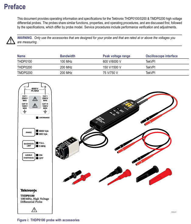
Product model parameters and core characteristics
1. Comparison Table of Core Parameters of Three Probes
Parameter category THDP0100 THDP0200 TMDP0200
Bandwidth (-3dB) DC~≥ 100MHz 150V range: DC~≥ 160MHz; 1500V gear: DC~≥ 200MHz 75V gear: DC~≥ 160MHz; 750V gear: DC~≥ 200MHz
Low range of peak voltage range: 600V (DC+peak AC); High range: 6000V (DC+peak AC) Low range: 150V (DC+peak AC); High range: 1500V (DC+peak AC) Low range: 75V (DC+peak AC); High range: 750V (DC+peak AC)
Attenuation ratio 600V gear: 100X; 6000V gear: 1000X; 150V gear: 50X; 1500V gear: 500X; 75V gear: 25X; 750V gear: 250X
Rise time (10%~90%,+20~30 ℃) ≤ 3.6ns (typical ≤ 3.5ns), slew rate ≥ 2500V/ns (6000V range) 150V range: ≤ 2.4ns (typical ≤ 2.2ns); 1500V gear: ≤ 2.0ns (typical ≤ 1.8ns), slew rate ≥ 650V/ns (1500V gear) 75V gear: ≤ 2.4ns (typical ≤ 2.2ns); 750V gear: ≤ 2.0ns (typical ≤ 1.8ns), slew rate ≥ 275V/ns (750V gear)
Gain accuracy ± 2% ± 2% ± 2%
Input resistance difference: 40M Ω± 2%; Single end to ground: 10M Ω± 2%/side differential: 10M Ω± 2%; Single end to ground: 2.5M Ω± 2%/side differential: 5M Ω± 2%; Single end to ground: 1.25M Ω± 2%/side
Input capacitance difference:<2.5pF; Single end to ground:<5.0pF/side difference:<2.0pF; Single end to ground:<4.0pF/side difference:<2.0pF; Single end to ground:<4.0pF/side difference
Common mode rejection ratio (CMRR) DC:>80dB; 100kHz:>60dB; 3.2MHz:>30dB; 100MHz:>26dB Same as THDP0100 Same as THDP0100
Maximum common mode voltage/ground voltage ± 6000V (DC+peak AC); 2300V CAT I; 1000V CAT III ± 1500V (DC+peak AC); 1000V CAT II; 600V CAT III ± 750V (DC+peak AC); 550V CAT I; 300V CAT III
Propagation delay 16ns 14ns 14ns
DC offset drift (output reference) 50 μ V/℃ 50 μ V/℃ 50 μ V/℃
Input overload recovery time in 600V range:<30ns (recover to the final value of 10% after 5 times overload); 6000V gear:<30ns 150V gear:<20ns 1500V gear:<20ns 75V gear:<20ns 750V gear:<20ns
Input equivalent noise (mV rms) 600V range:<175mV; 6000V range:<400mV; 150V range:<50mV; 1500V range:<140mV; 75V range:<25mV; 750V range:<65mV
Probe size (length x width x height) Probe body: 185mm x 56mm x 25mm; Control box: 76mm x 31mm x 41mm Same as THDP0100 Same as THDP0100
Cable length input line: 25.4cm (10in); Output line: 1.5m (59in) same as THDP0100 same as THDP0100
Weight (probe only) 340g (12.0oz) 309g (10.9oz) 309g (10.9oz)
2. Environmental adaptability parameters
Range of environmental parameter requirements
Working temperature: 0 ℃~40 ℃ (32 ℉~104 ℉)
Storage temperature -30 ℃~70 ℃ (-22 ℉~158 ℉)
Working humidity 5%~85% RH (0 ℃~40 ℃)
Storage humidity 5%~85% RH (≤ 40 ℃); 5%~45%RH(40℃~70℃)
Working altitude 3000m (9842ft)
Storage altitude 15240m (50000ft)
Operation Guide: Connection, Control, and Measurement
1. Connect to the measuring instrument (oscilloscope)
Physical connection: Insert the probe into the input channel of the oscilloscope, and all LEDs of the probe will briefly turn on and then return to the previous usage settings; The Status LED on the control box first turns amber (during self check), briefly goes off, and then turns green, indicating that the probe is ready.
Oscilloscope settings: Adjust the vertical offset (position) of the oscilloscope input, and select the appropriate probe range based on the measured signal voltage (low range has higher resolution and less noise, and high range needs to be switched when exceeding the range).
Security check: Confirm that the input impedance of the oscilloscope is 1M Ω and the bandwidth is not lower than the probe bandwidth; When the voltage is greater than 60VDC or 30VAC RMS, it is necessary to check again whether the accessory connections are secure.
2. Connect to the tested circuit
Connection line selection: Use the probe's built-in integral input line (25.4cm) or extension line (1.5m, paired to ensure consistent line length and reduce noise and inductance effects).
Accessory connection: Select accessories (such as hook tips, clamps, etc.) based on the type of test point, first connect the accessories to the probe input line, ensure a secure connection, and then connect them to the test circuit; Do not directly connect the voltage source when the accessory is not connected to the probe.
Measurement distance: Extending the cable can increase the distance between measurement points to 3.5m, but the measurement accuracy will decrease when the frequency is greater than 10MHz. It is recommended to use an oscilloscope with a bandwidth filter of 20MHz or below.
3. Detailed explanation of probe controls and indicator lights
Function description of control/indicator light position
Press the probe release button on the control box to unlock the connection between the probe and oscilloscope. First, disconnect the circuit and then unplug the probe
Status LED control box amber: self-test in progress; Green: Normal ready; Amber/Red: self-test failure or malfunction
The MENU button control box brings up the probe setting menu on the oscilloscope, which can operate functions such as AutoZero and range selection
The voltage range (RANGE) button and LED probe head switch between low/high range, and the LED displays the current range; Overrange LED lights up when exceeding the limit
BANDWIDTH LIMITED button and LED probe head switch to full bandwidth/5MHz limit; 5MHz can filter out high-frequency noise and harmonics in switch mode power supplies, suitable for SMPS testing
Overrange indicator light: The probe head of the probe lights up red: the differential signal exceeds the linear range of the current range, and the output signal is inaccurate
AUDBLE OVERRANGE button and LED probe head switch over range buzzer function (default enabled); ON/OFF LED indicates the current status
4. Key precautions for measurement
Limitations of Over Range Detection: OVERRANGE only detects differential over range between+/- inputs and does not detect common mode voltage or ground voltage over range. It is necessary to confirm that there is no over range situation through single ended measurement (ground at the - end and ground voltage at each point at the+end).
Common mode signal suppression: Twisted pair input lines can reduce noise coupling in high EMI environments; The higher the frequency, the lower the common mode rejection ratio, and the accuracy of the signal needs to be evaluated based on the measured frequency.
Probe load effect: The probe will introduce resistance, capacitance, and inductance into the tested circuit. When the frequency is greater than 1kHz, the input impedance decreases, and the load effect of low impedance and low-frequency signals can be ignored.
Accessory System: Standard Configuration and Optional Accessories
1. Standard accessories (by model)
(1) THDP0100 standard accessories
Accessory Name, Specification, Parameter Quantity, Revised Model
Extension cable length 1.5m, banana plug, 1000V CAT III, 600V CAT IV 1 pair 196-3523-xx
Test probe (TATP) 6-32 threaded head, with finger protection, 2300V CAT I, 1000V CAT II 1 pair included in 020-3070-xx kit
TASH compatible TATP for small conductors, 2300V CAT I, 1000V CAT II 1 pair included in 020-3070-xx kit
TALH compatible TATP for bolt terminals and busbars, 2300V CAT I, 1000V CAT II 1 pair included in 020-3070-xx kit
(2) THDP0200&TMDP0200 standard accessories
Accessory Name, Specification, Parameter Quantity, Revised Model
Extension cable length 1.5m, banana plug, 2300V CAT I, 1000V CAT III 1 pair 196-3523-xx
Handheld probe (TP175-FL) threaded head, extendable insulation sheath, 1000V CAT II/III, 10A 1 pair TP175-FL
Spring needle tip adapter and tip adapter TP175-FL, including conical tip and serrated tip, 150V CAT II, 0.1A 2 sets 020-3107-xx
Extended test probe adapter compatible with TP175-FL for dense circuits, 300V CAT II, 3A 1 pair 012-1724-xx
Hook clip (AC280-FL) banana interface, 1000V CAT III, 3A 1 pair AC280-FL
Clamp (AC283-FL) compatible with repeated test points, 1000V CAT III, 1A 1 pair AC283-FL
Crocodile clip (AC285-FL) large-sized insulation clip, 1000V CAT III, 10A 1 pair AC285-FL
Crocodile clip (344-0670-xx) double insulated, suitable for large bolts/busbars, 1000V CAT III, 10A 1 pair 344-0670-xx
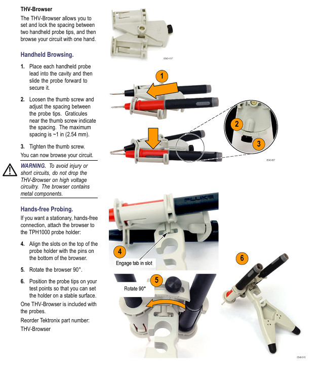
The probe holder (TPH1000) supports hands-free measurement with handheld probes and requires one TPH1000 rubber foot
THV Browser adjusts the distance between two probes (maximum 2.54cm), supports one handed browsing or hands-free measurement of one THV Browser
2. Optional accessories
Accessory Name, Function, Usage, Re order Model
TekVPI calibration fixture provides probe power supply and routes output signals to SMA interface for performance verification and gain adjustment 067-1701-xx
Replace the label (safety component) to cover the repair adjustment hole on the back of the probe, and replace it after repair to ensure safety 335-2913-xx
3. Restrictions on the use of accessories
The test probe and hook tip of THDP0100 are prohibited from being used in CAT III/IV circuits; When used in conjunction with THDP0200/TMDP0200, it is prohibited to use it on circuits with voltages greater than 1000V.
The spring needle tip adapter and the extended test probe adapter will lower the probe voltage level, and their rated voltage (150V CAT II/300V CAT II) must be strictly followed.
When using TP175-FL for CAT III circuit measurement, the probe tip should be retracted (approximately 3.7mm of exposed metal) to prevent arc flashover.
Functional inspection and calibration process
1. Function check (quick verification of probe availability)
(1) Preparation for Inspection
Equipment: Oscilloscope, AC power supply, probe standard accessories.
Prerequisite: When the accessories are fully connected and the voltage source is greater than 42Vpk, it is necessary to confirm that the connection is firm.
(2) Inspection steps and judgment criteria
Input 1 (+/-) Input 2 (-/+) Measurement mode range setting check standard
High range (6000V/1500V/750V) oscilloscope display line voltage with no significant distortion for live wire ground/neutral wire differential
The live/neutral differential low range (600V/150V/75V) oscilloscope displays the line voltage, and the OVERRANGE light lights up when the input exceeds the range by about 20%
No signal display on the common mode high/low range oscilloscope with live wire (same connection point) (AutoZero is required to offset DC offset)
2. Calibration operation (including AutoZero and offset adjustment)
(1) AutoZero (offsetting DC offset)
Preheating: Connect the probe and oscilloscope to power for 20 minutes.
Short circuit input: Use the hook tip to short-circuit the probe+/- input.
Start calibration: Press the probe MENU button, select "AutoZero" from the "Probe Setup" menu on the oscilloscope, and wait for calibration to complete.
(2) DC offset zero adjustment (manual)
Oscilloscope setting: Set the vertical offset of the probe channel to 0V.
Short circuit input: Use a hook tip to short-circuit the probe+/- input.
Enter adjustment mode: Long press the BANDWIDTH LIMITED and RANGE buttons on the probe for about 2 seconds until the OVERRANGE LED flashes and then release.
Adjust the zero position: Use the BANDWIDTH LIMITED and RANGE buttons to adjust the offset voltage displayed on the oscilloscope to 0V.
Storage settings: Press the AUDBLE OVERRANGE button, the OVERRANGE LED stops flashing, and the settings take effect.
Repeat: Switch to another range and repeat steps 3-5.
(3) DC offset zero reset (restore default)
Short circuit input: Use a hook tip to short-circuit the probe+/- input.
Enter reset mode: Long press the BANDWIDTH LIMIT and RANGE buttons for about 4 seconds until the OVERRANGE LED stays on, then release.
Store default value: Press the AUDBLE OVERRANGE button, the OVERRANGE LED will turn off, and the default offset value will be restored.
Repeat: Switch to another range, repeat steps 2-3, and then perform DC offset zero adjustment again.
3. Performance verification (officially recommended 1-year calibration interval)
(1) Required equipment
Minimum requirements for device name, example model
Oscilloscope bandwidth ≥ 500MHz Tektronix MSO/DSO4000
Signal generator ± 100V adjustable amplitude, 100Hz square wave, calibrated Fluke 9100
Pulse generator output ≥ 50V, pulse width ≥ 200ns, rise time ≤ 500ps, 1kHz Avtech AVR-E2-B-W-P
Calibration fixture TekVPI input interface Tektronix 067-1701-xx
The digital multimeter (DMM) supports a true RMS AC range of 100mV/1V with an accuracy of less than ± 0.3%. Tektronix DMM4040/4050
Cable and adapter 50 Ω BNC coaxial cable (36in), BNC-SMA adapter, BNC - double banana adapter, etc. Tektronix 012-0482-xx, 015-1018-xx, etc
Terminal load 50 Ω BNC through terminal Tektronix 011-0049-xx
Attenuator 50 Ω BNC, 2X attenuation Tektronix 011-0069-xx
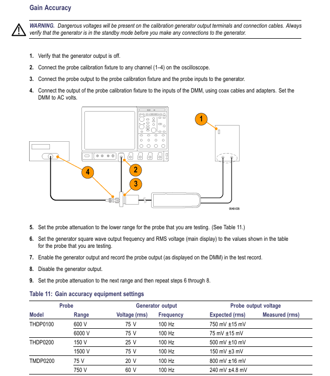
(2) Gain accuracy verification
Device connection:
Oscilloscope channel connected to calibration fixture → probe output connected to calibration fixture, probe input connected to signal generator through adapter;
The SMA interface of the calibration fixture is connected to the DMM through a coaxial cable, and the DMM is set to AC voltage mode.
Parameter setting and measurement (adjusted by model)
|Probe model | Range | Generator setting (100Hz square wave) | Expected DMM reading (rms) | Qualified range|
| THDP0100 | 600V | 75V rms | 750mV | 735mV~765mV(±2%) |
| THDP0100 | 6000V | 75V rms | 75mV | 73.5mV~76.5mV(±2%) |
| THDP0200 | 150V | 25V rms | 500mV | 490mV~510mV(±2%) |
| THDP0200 | 1500V | 75V rms | 150mV | 147mV~153mV(±2%) |
| TMDP0200 | 75V | 20V rms | 800mV | 784mV~816mV(±2%) |
| TMDP0200 | 750V | 60V rms | 240mV | 235.2mV~244.8mV(±2%) |
Operation steps:
Turn off generator output → Set probe range and generator parameters → Turn on generator → Record DMM reading → Turn off generator → Switch range and repeat measurement.
(3) Rise time verification
Device connection:
Pulse generator output → 2X attenuator → 50 Ω terminal → BNC - dual banana adapter → probe input (+/-);
Connect the probe to the oscilloscope and keep the input line straight and parallel.
Parameter settings:
Pulse generator: 50V output, 1kHz frequency, 200ns pulse width (probe input actual 25V, due to 2X attenuation);
Oscilloscope: 5V/div, 10ns/div, full bandwidth, average of 16 samples;
Probe: Full bandwidth, corresponding range.
Measurement and Qualification Standards:
Turn on the generator and use an oscilloscope to automatically measure the rise time → record the value → switch the range and repeat the measurement;
Qualification criteria: THDP0100 range ≤ 3.6ns; THDP0200 150V range ≤ 2.4ns, 1500V range ≤ 2.0ns; TMDP0200 75V range ≤ 2.4ns, 750V range ≤ 2.0ns.
4. Internal adjustment (limited to probes with serial number C020000 and above)
(1) Adjustment premise
The safety label on the back of the probe needs to be removed (must be replaced after repair) and an insulation adjustment tool should be used.
Preheat for 20 minutes before adjustment, strictly follow the high-voltage operation specifications (professional personnel are required for voltage>30VAC RMS).
(2) Adjustable projects and processes
Adjust the reference standards for the core steps of the project
Gain accuracy 1. Connect the calibration fixture, generator, and DMM; 2. Verify parameter settings based on gain accuracy; 3. Use insulation tools to adjust the DC gain potentiometer of the corresponding range, so that the DMM reading is within the qualified range and meets the gain accuracy verification standard (± 2%)
DC CMRR 1. Connect the two inputs of the probe to the generator+terminal, and set the generator parameters according to the table; 2. Set the oscilloscope to 10ms/div and 5MHz bandwidth; 3. Adjust the DC CMRR potentiometer to minimize the signal amplitude displayed on the oscilloscope. The signal amplitude should be minimized without significant fluctuations
LF compensation 1. Probe input connected to generator for fast rising edge output (10kHz, 50Vp-p); 2. Set the oscilloscope to 4 μ s/div, averaging 16 times; 3. Adjust in the order of "long+LF → long+LF * → short+LF" (TMDP0200 without+LF *); 4. Reverse the input line and adjust the square wave response optimization by pressing "Long LF → Long LF * → Short LF", without overshoot or attenuation
AC CMRR 1. Connect the two inputs of the probe to the generator+terminal, and set the generator to 297Vp-p (105Vrms) and 100kHz; 2. Set the oscilloscope to 10 μ s/div and probe to full bandwidth; 3. Fine tune+LF potentiometer (short+LF → long+LF → long+LF *) to minimize signal amplitude. The signal amplitude is minimized, and CMRR conforms to typical values
(3) DC CMRR generator parameter settings
Probe Model Range Generator Voltage (rms) Generator Voltage (p-p) Frequency
THDP0100 600V 353.53V 1000V 40Hz
THDP0200 150V 200V 566V 40Hz
TMDP0200 75V 353.53V 1000V 40Hz
Troubleshooting and Maintenance
1. Common faults and solutions
Troubleshooting steps for possible causes of fault phenomena
The probe LED does not light up frequently. There are interface and channel faults between the probe and oscilloscope. 1. Disconnect and reconnect the probe; 2. Replace the oscilloscope channel; 3. Restart the oscilloscope and reconnect it; 4. Replace the oscilloscope for testing (if the fault follows the probe, it needs to be returned to the factory)
The oscilloscope has no signal and the display accessories are not fully connected, the probe and circuit are loose, and the probe is faulty. 1. Check whether the accessory connections are firm (banana plugs and clamps need to be fully inserted); 2. Reconnect the probe to the tested circuit and confirm good contact; 3. Perform functional checks to verify if the probe is functioning properly; 4. Check the oscilloscope channel settings (such as coupling mode and range)
The OVERRANGE light is abnormally on, and the differential signal is out of range and the common mode voltage/ground voltage is out of range. 1. Switch to a higher range and observe if the light goes out; If it is already at the highest range, stop measuring and check the measured signal; 3. Perform single ended measurement to confirm that the common mode voltage and ground voltage do not exceed the rated value of the probe
Measurement signal distortion: Insufficient probe bandwidth, input line not twisted, load impact: 1. Confirm that probe bandwidth is ≥ measured signal frequency; 2. Twist the input line to reduce noise coupling; 3. Evaluate the impact of probe load on the tested circuit and replace the high input impedance probe if necessary
The gain accuracy probe is not calibrated and the environmental temperature and humidity exceed the standard. 1. Perform AutoZero calibration; 2. Re calibrate the gain according to the performance verification process; 3. Confirm that the measurement environment is within the range of 0 ℃~40 ℃ and 5%~85% RH
2. Firmware upgrade
If the oscilloscope does not display all probe controls/indicator lights or frequently malfunctions, it may be necessary to upgrade the oscilloscope firmware.
3. Maintenance and upkeep standards
(1) Cleaning requirements
Cleaning tools: dry lint free cloth, soft bristled brush; Wipe stubborn stains with a cloth/cotton swab dampened with 75% isopropanol.
Prohibitions: It is prohibited to use spray, liquid solvent and abrasive; Prohibit moisture from entering the interior of the probe; Do not clean the internal components of the probe.
(2) Maintenance restrictions
There are no user repairable parts. Probes with serial number C019999 and below can only perform AutoZero and DC offset adjustment. Other faults need to be returned to the factory.
Repair request: Contact a Tektronix service representative or authorized repair center to return the product for repair according to the instructions.
Key usage risks and avoidance suggestions
High voltage electric shock risk: Strictly follow the connection/disconnection sequence, use designated accessories, wear insulation protective equipment when the voltage is greater than 60VDC/30VAC RMS, and do not touch exposed circuits.
Risk of probe damage: Do not use beyond the range or environmental conditions; Unauthorized disassembly and assembly are prohibited; Prohibit the use of worn or non certified accessories.
Measurement error risk: Perform AutoZero calibration before measurement; Pay attention to the decrease of common mode rejection ratio during high-frequency measurement; When using an extension cable, it should be paired with a low bandwidth filter; Regularly (1 year) conduct performance validation.
Environmental safety risks: Do not use in damp, explosive, and dusty environments; Ensure good heat dissipation of the probe and avoid prolonged high-temperature operation.
- OMRON
- ABB
- General Electric
- EMERSON
- Honeywell
- HIMA
- ALSTOM
- Rolls-Royce
- MOTOROLA
- Rockwell
- Siemens
- Woodward
- YOKOGAWA
- FOXBORO
- KOLLMORGEN
- MOOG
- KB
- YAMAHA
- BENDER
- TEKTRONIX
- Westinghouse
- AMAT
- AB
- XYCOM
- Yaskawa
- B&R
- Schneider
- KONGSBERG
- NI
- WATLOW
- ProSoft
- SEW
- ADVANCED
- Reliance
- TRICONEX
- METSO
- MAN
- Advantest
- STUDER
- DANAHER MOTION
- Bently
- Galil
- EATON
- MOLEX
- DEIF
- B&W
- ZYGO
- Aerotech
- DANFOSS
- Beijer
- Moxa
- Rexroth
- Johnson
- WAGO
- TOSHIBA
- BMCM
- SMC
- HITACHI
- HIRSCHMANN
- Application field
- XP POWER
- CTI
- TRICON
- STOBER
- Thinklogical
- Horner Automation
- Meggitt
- Fanuc
- Baldor
- SHINKAWA
- Other Brands
- UniOP
- KUKA
- Iba
- Beckhoff
- ADLINK
-
 GE Fanuc VMIVME-5588 High-speed Reflective Memory Board
 -
 VMIC VMIVME-5565 Reflective Memory Board
 -
 VMIC VMIVME-2127 Voltage Source Digital Output Board
 -
 VMIC VMIVME 4512 Analog VME Process PCB Assembly
 -
 GE Fanuc VMIVME-3122-022 Analog I/O Module
 -
 VMIC VMIVME 5576 High Speed Fiberoptic Network Board
 -
 FANUC VMIVME-7452 VMEbus Analog I/O Board
 -
 FANUC VMIVME-2210 VMEbus Digital Output Board
 -
 FANUC VMIVME-7750-734000 VMEbus Single Board Computer
 -
 VMIC VMIVME 2210 VMEbus DO 28V Digital Output Board
 -
 VMIC VMIVME DR11W VMEbus DMA Interface Module
 -
 VMIC VMIVME-2536-200 5V Optically Coupled Digital I/O Board
 -
 VMIC VME-7754 VMIVMF7754-259000 VMEbus Control Card
 -
 VMIC 2170A VME Interface Board
 -
 GE VMIC PMC-5565PIORC-210000 Reflective Memory PMC Node Card
 -
 VMIC VMIVME-7750-750000 VME Single Board Computer
 -
 VMIC VMIVME-7751 VME Single Board Computer
 -
 VMIC 332-004512 Analog VME Process Board
 -
 VMIC VMIVME2528 VME Interface Board
 -
FANUC VMIVME-2120 VME Bus Interface Board
-
 FANUC VMIVME-2540 VME Bus Interface Board
 -
 FANUC VMIVME-3230 VME Bus Interface Board
 -
 FANUC VMIVME-4514 VME Bus Interface Board
 -
 ETEL DSB2S154-211E-000H Servo Amplifier
 -
 ETEL DSCQT112-111-000 Motion Control Module
 -
 ETEL LMG20-050-3QB-211A Servo Motor – High Torque Linear
 -
 ETEL EU-LCP-0-0-1000-01 Communication Card
 -
 ETEL DSA2P174ZA-033A Servo Amplifier Driver
 -
 ETEL EA-P2M-400-15/40A-0100-00 Servo Driver
 -
 ETEL DSC2P152-111-000 Servo Drive Amplifier
 -
 ETEL LMS15-050-3UA-209A Linear Motor
 -
ETEL DSC2P152-111D-000A Controller
-
 ETEL DSB2P131-111E-000B Digital Servo Amplifier Position Controller
 -
 ETEL DSO-PWR111C-000B Power Supply Module
 -
 ETEL DSCDP324-321F-000C Servo Driver
 -
 ETEL DSC2P152-111B-000D Controller
 -
 ETEL DSB2P142-111E-000H Circuit Board
 -
 ETEL LMG05-030-3QA-H01 Linear Motor
 -
 ETEL DSC2P152-111F-000A Controller
 -
 ETEL DSA2S211ZA Servo Drive
 -
 ETEL DSCDM332-112-000 Drive Module
 -
 ETEL DSCDP334-421-000 Digital Position Controller Servo Drive
 -
ETEL EA-P2M-400-15/40A-0100-00 AccurET Servo Drive
-
 ETEL TMA0140-050-3UB-202B Torque Motor
 -
 ETEL DSA1DL1D.PCB Servo Drive Board
 -
 ETEL DSA2DL 1A Servo Drive
 -
 ETEL DSMAX111B-000B Servo Drive
 -
ETEL DSO-PWS111C-000B Power Supply Module
-
 ETEL DSC2P142-111B-000D Servo Drive Amplifier
 -
 ETEL DSC2P132-111D-000A Servo Drive Amplifier
 -
ETEL DSC2P152-111B-000D Servo Drive Amplifier
-
ETEL DSB2P131-121E-000H Servo Drive Amplifier
-
 ETEL DSB2P142-111E-000H Servo Drive Amplifier
 -
ETEL DSO-PWR112C-000A Power Supply Module – High Power
-
ETEL DSO-PWR111C-000A Power Supply Module
-
ETEL DSB2P121-121E-000H Servo Drive Amplifier
-
 ETEL DSB2S134-111E-000H Digital Servo Amplifier
 -
 ETEL RTMA0140-070-AQN-21E Motor
 -
ETEL DSCDP132-111-000 Dual Controller Circuit Board – Motion Control
-
 ETEL LMS15-050-3UA-209Aft Linear Motor
 -
 ETEL DSCDP324-322G-000A Position Controller
 -
ETEL DSA2P174ZA-033A Servo Amplifier Driver
-
 ETEL DSA2P174ZA-017A Servo Amplifier Driver
 -
 ETEL LMD10-050-3QA-223A Linear Motor
 -
ETEL EU-LGP-0-0-1000-00 PCI Network Card
-
ETEL DSO-PWS111C-000B Power Supply Module
-
ETEL DSC2V174-111C-001A Servo Controller
-
 ETEL EA-P2M-600-15/40A-0000-01 AccurET Modular Position Controller
 -
 ETEL RTMA0140-070-AQN-21B DD Motor
 -
 ETEL DSC2P144-421-000 Servo Driver
 -
ETEL EA-P2M-400-15-40A-0100-00 Servo Drive
-
ETEL DSCDM341-111C-000B Board
-
 ETEL LMD10-050-3QA-223A Motor
 -
ETEL RTMA0140-070-AQN-21E DD Motor
-
 ETEL DSCDM342-111-000 Servo Variator
 -
ETEL DSC2P152-111E-000A Servo Amplifier
-
ETEL LMS15-050-3UA-209A Motor
-
ETEL RTMA0140-070-AQN-21C DD Motor – High Torque Direct Drive
-
 ETEL DSCDP334-421G-000A Servo Drive
 -
Etel DSB2S154-211E-000H Digital Servo Amplifier
-
 ETEL EA-P2M-400-15/40A-0100-00 AccurET Servo Drive
 -
 ETEL DSA2P-174ZA-017A Digital Servo Amplifier
 -
ETEL EA-P2M-400-15/40A-0100-00 Servo Drive
-
ETEL LMP07-100-3TAS-229 Linear Motor Primary Part
-
ETEL LMA11-120-3ZA-359A Linear Motor
-
 ETEL EA-S0M-400-40/80A-0000-00 Drive Power Supply
 -
Etel DSCDP334-421-000 Driver
-
ETEL DSCDM341-111C-000B DSCDM Drive Board
-
Etel DSA1 Digital Servo Amplifier
-
ETEL DSA2P174ZA-033A Servo Amplifier
-
ETEL DSCDM342-111-000 Servo Verifier
-
 ETEL LMS15-050-3UA-209A Linear Motor
 -
ETEL P2M-048-2.5/5A AccurET Position Controller – Modular
-
ETEL LMD10-050-3QA-223A Linear Motor – Compact Precision
-
 ETEL EA-P2M-400-05/10A-0000-01 Drive – Precision Motion
 -
ETEL LMP07-100-3TAS-229 Linear Motor Primary Part
-
 ETEL EU-LGP-0-0-0000-00 Motion Control Card – Precision Control
 -
 ETEL DSC2P152-111E-000A Servo Amplifier
 -
ETEL EA-P2M-400-15/40A-0100-01 Servo Drive
-
 ETEL EA-SOM-300-40/80A-0000-00 AccurET Power Supply Module
 -
ETEL LMG10-1050-3QA-H01 Linear Motor
-
 ETEL EA-SOM-300-40/80A-0000-00 AccurET Modular Power Supply
 -
ETEL EA-P2M-400-15/40A-0100-00 AccurET Servo Drive
-
 ETEL EA-P2M-400-15/40A-0100-01 Servo Driver
 -
Etel RTMA0140-070-AQN-21B High Speed Motor
-
ETEL DSC2P141-111-000 Linear Servo Amplifier
-
ETEL DSB2S134-211E-000H Digital Servo Amplifier
-
ETEL 3LM-23C Motion Controller
-
Etel DSO-SER211-000 Power Add-On Board
-
ETEL DSCDP334-421-000 Servo Drive
-
 CTI-Cryogenics 8116071G001 Enhanced On-Board 8F Cryopump
 -
ETEL LMD10-050-3QA-223A Linear Motor
-
Etel DSO-SER211-000 Servo Card Power Add-On
-
ETEL LMG05-050-3QA-213A Linear Motor
-
Etel DSO-SER211-000 Power Add-On Board
-
ETEL EU-LGP-0-0-0000-00 Motion Control Card
-
ETEL EA-P2M-400-15/40A-0100-00 AccurET Servo Drive
-
 ETEL DSA2P1540A Digital Servo Amplifier
 -
ETEL DSC2P131-111-000 Drive Board
-
ETEL DSC2P131-111D-000A Servo Drive
-
Etel SA-IL 03-208 Linear Motor Section 208mm
-
 ETEL EA-P2M-300-4/7.5A-0000-01 AccurET Position Controller
 -
ETEL DSO-SER211-000 Power Board
-
ETEL DSC2P131-111F-000A Servo Amplifier
-
ETEL DSA1P6242B Digital Servo Amplifier
-
ETEL DSC2P131-111B-000B Regulator
-
ETEL DSA2P1540A Digital Servo Amplifier
-
ETEL EA-P2M-048-2.5/5A-0100-01 Drive


