
TOSHIBA TOSBERT VF-A3 frequency converter
Equipment specifications:
Voltage level, power range, core application scenarios
200V level 0.4-55kW small and medium-sized motor drive (such as conveyor, fan)
400V level 0.75-75kW medium and large motor drive (such as pumps and compressors)
TOSHIBA TOSBERT VF-A3 frequency converter
Overview and Basic Equipment Information
Positioning: The official user manual for Toshiba TOSBERT VF-A3 series high-performance frequency converters, used to guide users in installation, operation, maintenance, and troubleshooting.
Equipment specifications:
Voltage level, power range, core application scenarios
200V level 0.4-55kW small and medium-sized motor drive (such as conveyor, fan)
400V level 0.75-75kW medium and large motor drive (such as pumps and compressors)
Equipment features:
High reliability: Built in current limiting, retry, soft stop, and instantaneous power-off protection functions to reduce the probability of tripping.
Easy to operate: keyboard style operation panel, supports memory commands, basic settings do not require stopping the machine to consult the manual.
Compact design: The research body integrates multiple protection functions, saving installation space.
Model coding rules: Taking "VFA3-2150P" as an example, the meanings of each part are as follows:
VFA3: Series Code (VF-A3 Series)
2: Voltage level (2=200V level, 4=400V level)
15: Capacity (15kW)
0: Special configuration (0=Standard)
P: Panel configuration (P=equipped with operation panel)
Installation and wiring specifications
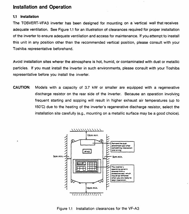
1. Installation requirements
Installation method: Only supports vertical wall mounted installation. For non vertical installation, please consult a Toshiba representative.
Ventilation gap (Figure 1.1):
Top/bottom: minimum 10cm
Left and right sides: minimum 5cm
Environmental restrictions:
Temperature: -10 ℃~40 ℃ (up to 50 ℃ without casing)
Humidity: ≤ 90%, no condensation
Altitude: ≤ 1000m (3300ft)
Vibration: Acceleration ≤ 0.5G (20-50Hz), amplitude ≤ 0.1mm (50-100Hz)
Special note: Models with 3.7kW and below have a built-in regenerative discharge resistor on the back. Frequent start stop cycles can cause the exhaust temperature to reach 150 ℃. It is recommended to install it on a metal surface for heat dissipation.
2. Wiring process and specifications
Preparation before wiring:
Disconnect the main switch of the distribution panel and confirm that the "CHARGE" light of the frequency converter is off (to avoid electric shock).
Open the front cover: Pull forward and lift up (Figure 1.2).
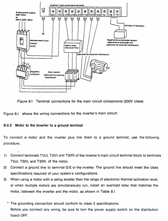
Main circuit wiring (Figure 1.3):
Terminal Name Connection Object Precautions
L1/R, L2/S, L3/T 3-phase power input cannot be reversed to the motor end (T1/U, etc.), otherwise the equipment will be damaged
T1/U, T2/V, T3/W 3-phase motors require corresponding motor U, V, and W terminals
The grounding wire of the G/E system complies with Class 3 grounding specifications
R1/T1 (200V level), R38/R41 (400V level) control circuit power supply single-phase signal, ensuring independent power supply for the control circuit
Control circuit wiring:
Frequency setting signal: PP (10Vdc reference) RR(0-10Vdc/0-5Vdc)、IV(0-5Vdc/4-20mAdc), The type needs to be switched through JP1/JP2 jumper (Table 6.1).
Operation control signals: ST (preparation for operation), F (forward rotation), R (reverse rotation), JOG (jog), short circuit the corresponding terminal to CC to achieve the function.
Taboo:
Do not connect power factor compensation capacitors on the power side or motor end.
The control circuit (excluding FLA/FLB/FLC) needs to be insulated from the main circuit to avoid interference.
Operation process and core function settings
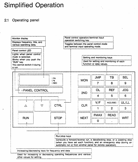
1. Operation panel and basic operations
Panel layout (Figure 2.1): including "PANEL CON" LED, MON (monitoring/setting switch), RUN/STOP (run/stop), frequency ± key, parameter setting key (WRT/READ/NEXT, etc.).
Simplify the operation process (trial run, recommended low-frequency startup):
Power ON: When the MCCB is closed, the monitor flashes "OFF" first and then displays "0.0".
Switch panel control: Press the "CTRL" key, and the "PANEL Control" LED will light up.
Set frequency:
Numerical keys: If set to 10Hz, press "1", "0", and "WRT" to display "10" and "FC" alternately.
± key: Long press "△" (increase)/"▽" (decrease), if set to 5.5Hz, press "WRT" to save.
Start/Stop: Press "RUN" to accelerate to the set frequency; Press' STOP 'to slow down and stop.
2. Core Function Settings
(1) Frequency and voltage characteristic settings
Maximum frequency (FH): 30-400Hz (1Hz step size), default 50Hz for 50Hz models and 60Hz for 60Hz models, cannot be modified during operation (requires shutdown).
Torque boost (ub): 0-30% (1% step size), default 3%, used to boost starting torque, excessive can cause overcurrent during startup.
Automatic torque boost (Rub): 0=off, 1=on, automatically adjusts voltage based on load current (Figure 3.4).
Fundamental frequency (uL): 25-400Hz (1Hz step size), set 50Hz for 50Hz motors and 60Hz for 60Hz motors (Table 3.1).
V/f mode (Pt.): 0=constant torque (conveyor), 1=variable torque (fan/pump, energy-saving) (Figure 3.6).
(2) Acceleration, deceleration, and braking control
Acceleration and deceleration time (ACC/DEC):
Range: 0.1-6000 seconds, supports 2 sets of time (ACC1/ACC2, DEC1/DEC2).
Mode: 0=linear, 1=non-linear 1 (slow acceleration at low torque), 2=non-linear 2 (slow acceleration at high speed) (Figure 3.8).
DC injection braking (dbF/dbu/dbt):
Starting frequency (dbF): 0-10Hz, braking voltage (dbu): 0-20%, braking time (dbt): 0-5 seconds, used for precise positioning (Figure 3.27).
Regenerative braking (Pb):
Applicable scenarios for Pb setting function
0 normal load without regenerative braking (or using regenerative discharge unit)
1. There is regenerative braking, no resistance overload detection, and moderate inertia load
2. There is regenerative braking and resistance overload detection for large inertia loads (such as centrifuges)
(3) Multi speed and special operation
Multi speed operation (S1-S7): 7 speeds are achieved through the combination of SS1/SS2/SS3 terminals, with a frequency range from the lower limit frequency (LL) to the upper limit frequency (UL), and can be controlled by panel or external signals (Table 3.7).
Jog operation (JOG): frequency 0-20Hz (0.1Hz step size), only starts when stopped, press the "RUN" button to run, release to stop (Figure 3.21).
Frequency jump (FJ1-FJ3): 3 jump points, set the jump frequency and width to avoid load resonance (Figure 3.24).
3. Status monitoring and fault reset
Operation/shutdown monitoring: Press the "NEXT" button to cycle through the status (Table 3.2), such as "60.0"=operating frequency 60Hz, "PSO. 0"=overvoltage limit activation, "OC"=overcurrent detection.
Fault monitoring: When tripping, press "NEXT" to check the fault status (such as frequency, current, voltage), and support tracing the last 4 faults (Table 3.4).
Fault reset:
Panel reset: Press "CLR"+"WRT".
External reset: Short circuit the RST-CC terminal (Figure 4.9).
Troubleshooting and Maintenance
1. Fault codes and solutions (Table 9.1)
Meaning of fault code and solution measures
OC1 acceleration overcurrent 1. Increase ACC time; 2. Reduce UB settings; 3. Check if there is a sudden change in the load
OH frequency converter overheating 1. Check the cooling fan; 2. Confirm that the ambient temperature is ≤ 40 ℃; 3. Clean the heat dissipation channel
EF load terminal grounding fault 1. Check the insulation of the motor and output circuit; 2. Check the grounding short circuit point
EEP EEPROM abnormality 1. Restart the power supply; 2. If ineffective, repair/replace EEPROM
2. Regular maintenance and storage
Regular inspection (every 3-6 months):
Terminal screws: Tighten loose screws to prevent poor contact.
Line inspection: Check if the wire crimping point is overheated (discolored) and if the insulation is damaged.
Dust removal: Use a vacuum cleaner to clean the ventilation openings and printed circuit board dust to avoid overheating.
Insulation test: Use a 500V megohmmeter to test the insulation of the main circuit. The motor needs to be tested after disconnecting the frequency converter.
Storage requirements:
Environment: Dry, dust-free, non corrosive gas, temperature -10-40 ℃.
Activation: Long term storage (>2 years) requires power on every 2 years; After removing the storage, the motor needs to be powered on for at least 5 hours before running.
Optional accessories and warranty terms
1. Optional accessories (Table 7.1/7.2)
Type Accessory Name Model Example Function
External installation of input reactor PFL2012-2100 improves power factor and suppresses harmonics
External installation of regenerative discharge resistor PBR3-2055 enhances braking effect, suitable for large inertia loads
Built in multi option printed circuit board VF3X-0888B supports RS-232C communication, BCD code input, etc
External installation of PANEL-KIT (1M/3M/5M) remote control panel, including 1/3/5 meter cable
2. Warranty terms
Warranty period: 12 months after delivery.
Warranty expiration situation:
Unauthorized maintenance/modification of equipment.
Damage caused by vibration/impact during transportation/installation.
Force majeure events such as fires, floods, lightning strikes, and abnormal power grid voltage.
Used for designated purposes of non industrial frequency converters.
Acceptance requirements: After opening the box, check that the equipment is undamaged and the model is consistent with the order. If there are any problems, immediately contact a Toshiba representative.
Key issues
Question 1: What are the space and environmental restrictions that must be followed when installing the TOSBERT VF-A3 frequency converter? What are the consequences of ignoring these restrictions?
Answer:
Restrictions that must be followed:
Installation method: Only supports vertical wall mounting, non vertical installation requires prior consultation with Toshiba representatives.
Ventilation gap: minimum 10cm at the top/bottom, and minimum 5cm on both sides to ensure smooth heat dissipation.
Environmental parameters: temperature -10 ℃~40 ℃ (≤ 50 ℃ without casing), humidity ≤ 90% (no condensation), altitude ≤ 1000m, vibration acceleration ≤ 0.5G (20-50Hz)/amplitude ≤ 0.1mm (50-100Hz).
Special models: Models with 3.7kW and below have regenerative discharge resistors on the back, and the exhaust temperature can reach 150 ℃. It is recommended to avoid installing on flammable surfaces and choose metal surfaces for heat dissipation.
The consequences of ignoring restrictions:
Insufficient ventilation can cause the frequency converter to overheat (fault code OH), triggering a protective shutdown and potentially damaging the power module in the long run.
Excessive humidity/condensation can cause a short circuit and ground fault (EF code) in the main circuit.
Excessive vibration may cause loose terminals, poor contact leading to overcurrent (OC code) or equipment shutdown.
Question 2: In the daily operation of VF-A3 frequency converter, how to set the "DC injection braking" function through the panel to achieve precise motor stop? It is necessary to clarify the setting range and default values of key parameters.
Answer: The steps and key parameters for setting "DC injection braking" through the panel are as follows:
Enter the second functional mode:
Press the "MON" button, and the display will show "no.0 →: t: JP"; Press the "2ND" key to switch to the "2nd" mode.
Select DC injection braking related parameters (function number 0, Table 3.1):
Parameter Name Function Setting Range Default Value Operation Instructions
When the DBF (DC injection braking start frequency) motor drops to this frequency, it triggers the braking 0-10Hz (0.1Hz step size) 0Hz. Press "READ" to read the current value, press "△/▽" or the numerical key to adjust, and press "WRT" to save
DBU (DC injection braking voltage) injects a DC voltage that accounts for 0-20% (1% step size) during braking. If the voltage is too high, it will cause the motor to overheat. It is recommended to adjust according to the inertia of the load (such as 10% -15%)
DBT (DC injection braking time) braking duration 0-5 seconds (0.1 second step) 0 seconds. It is necessary to ensure that the time is sufficient to stop the motor and avoid incomplete braking caused by too short a time
Confirm settings: Press the "MON" key to return to the original display (frequency/OFF), and the settings will take effect.
Attention: DC injection braking is only activated during deceleration and stopping process, and should be accompanied by appropriate deceleration time (DEC) to avoid triggering overcurrent protection due to excessive current during braking.
Question 3: What are the possible reasons when the VF-A3 frequency converter displays "OC1" (acceleration overcurrent) fault? What are the corresponding solutions? What safety precautions should be taken during troubleshooting?
Answer:
Reason for "OC1" fault: During acceleration, the main circuit current exceeds the protection threshold. Common reasons include:
The acceleration time (ACC) is set too short, and the motor speed cannot keep up with the frequency increase, resulting in excessive stalling current.
The torque boost (ub) is set too high, causing overcurrent due to high voltage during startup.
Sudden load changes in the motor (such as sudden blockage of the conveyor), and the load current exceeds the rated output of the frequency converter.
Poor wiring of the main circuit (such as loose wiring at the motor end) can cause current fluctuations.
Solution:
Extend acceleration time: Enter the first function ("MON" → select function number 2), adjust "ACC1/ACC2" to a longer time (such as changing from 1 second to 3 seconds), and press "WRT" to save.
Reduce torque boost: Enter the first function (function number 1), reduce the "ub" value (such as from 10% to 5%), and avoid starting overvoltage.
Check the load: Check if the mechanical load is stuck, clean up foreign objects or reduce the load to ensure that the load is within the rated range of the motor.
Check wiring: Disconnect the power supply (MCCB), confirm that the "CHARGE" light is off, tighten the terminal screws of the main circuit (L1/R, T1/U, etc.), and check the insulation of the circuit.
Check safety precautions:
Before checking all wiring, the main switch of the distribution panel must be disconnected and wait for the "CHARGE" light to turn off (to avoid electric shock caused by residual voltage of the capacitor).
When adjusting parameters, it is necessary to ensure that the frequency converter is in a stopped state. Modifying acceleration time/torque increase during operation may cause equipment instability.
If the fault still exists after multiple troubleshooting, it is necessary to check the motor insulation (using a 500V megohmmeter) to avoid overcurrent caused by internal short circuit of the motor.
- OMRON
- ABB
- General Electric
- EMERSON
- Honeywell
- HIMA
- ALSTOM
- Rolls-Royce
- MOTOROLA
- Rockwell
- Siemens
- Woodward
- YOKOGAWA
- FOXBORO
- KOLLMORGEN
- MOOG
- KB
- YAMAHA
- BENDER
- TEKTRONIX
- Westinghouse
- AMAT
- AB
- XYCOM
- Yaskawa
- B&R
- Schneider
- KONGSBERG
- NI
- WATLOW
- ProSoft
- SEW
- ADVANCED
- Reliance
- TRICONEX
- METSO
- MAN
- Advantest
- STUDER
- DANAHER MOTION
- Bently
- Galil
- EATON
- MOLEX
- DEIF
- B&W
- ZYGO
- Aerotech
- DANFOSS
- Beijer
- Moxa
- Rexroth
- Johnson
- WAGO
- TOSHIBA
- BMCM
- SMC
- HITACHI
- HIRSCHMANN
- Application field
- XP POWER
- CTI
- TRICON
- STOBER
- Thinklogical
- Horner Automation
- Meggitt
- Fanuc
- Baldor
- SHINKAWA
- Other Brands
- UniOP
- KUKA
- Iba
- Beckhoff
-
 Basler BE1-25 Time Overcurrent Relay M1FA6PA4S0F
 -
 Basler SR4A2B05B3E Static Voltage Regulator
 -
 Basler DECS-200-2L Digital Excitation Control
 -
 Basler BE303280001 Control Transformer
 -
 Basler 9262103004 Voltage Regulator Board For Basler DECS-400
 -
 Basler ICRM-7 Inrush Current Reduction Module
 -
 Basler BE1-32R Power Relay
 -
 BASLER ELECTRIC KR4F VOLTAGE REGULATOR 9042600100 600V 50/60Hz
 -
 Basler 9222600101 Power Module
 -
 Basler SR8A-2B15B3A Static Voltage Regulator
 -
 BASLER BE1-87G G1E A1L A0N1P Generator Differential Relay w/ Reactor 9170818100
 -
Basler 9284900101 DECS Power Module
-
 Basler PRS250 Veri-Sync Relay
 -
 Basler BE 12296 001 Transformer
 -
 Basler 905970-104 Rev.M Voltage Regulator
 -
Basler BE1-87T Transformer Differential Relay
-
 Basler SR8A-2B15B3A Static Voltage Regulator
 -
 Basler SR32A2B05B3E Static Voltage Regulator
 -
 Basler SR4A-2B16B3A Static Voltage Regulator
 -
 Basler SR32A-2B13B3E Static Voltage Regulator
 -
 Basler KR4F Voltage Regulator 9042600100
 -
 Basler SSR 32-12 Static Voltage Regulator 400Hz
 -
 Basler CBS 212A Current Boost System
 -
 Basler MVC236 Manual Control Module
 -
Basler UFOV Protective Module 9040000100
-
 Basler SSR 125-12 Static Voltage Regulator
 -
 Basler SR4A2B10A3E Static Voltage Regulator
 -
 Basler BE1-25 Solid State Time Overcurrent Relay
 -
 Basler MVC 232 Manual Voltage Control Module
 -
Basler PRS 250 Veri-Sync Relay
-
 Basler UFOV 260A Under Frequency Over Voltage Relay
 -
 Basler RUL2098-10GC Load Relay
 -
 Basler 9 1049 04 100 PC Board
 -
Basler 125-12 Static Voltage Regulator
-
Basler PRS 250 Veri-Sync Relay
-
Basler 9185900102 SSR 125-12 Regulator
-
Basler BE12819001 Reactor
-
 Teradyne 535-100-00 Power Supply
 -
 Basler BE1-67 Directional OC Relay
 -
 Basler PRP110 Reverse Power Relay
 -
 Basler BE30631001 Isolation Transformer
 -
 Basler DECS-200-2L Digital Excitation Control
 -
 Basler BE1-47N Voltage Phase Sequence Relay
 -
 Basler AEC63-7 Analog Excitation Controller 220-277V
 -
Basler BE1-50/51B-107 Overcurrent Relay
-
 Basler Electric BE1‑32R BE1‑E1P‑BON0F Protective Relay
 -
Basler BE1-25 Solid State Time Overcurrent Relay M1EA6PA5S1F
-
 Basler MVC 232 Manual Voltage Control Module 90 37000 103 60VAC 55VDC
 -
Basler RAL6144-16GM Racer GigE Line Scan Camera
-
Basler SSR 63-12 Static Voltage Regulator
-
 Basler BE1-51A Overcurrent Relay
 -
Basler BE1-87T Solid State Protective Relay
-
Basler SR4A2B01B3A Static Voltage Regulator
-
 Basler SSR 32-12 Static Voltage Regulator
 -
 Basler TRR00696 Transformer 1KVA 115V
 -
 Basler DECS-100-B15 AVR Replacement
 -
Basler BE1-27 Under-Voltage Relay
-
 Basler ACA2000-50GM Interface Module
 -
 Basler AEC63-7 Analog Excitation Controller
 -
Basler PRS 250 Veri-Sync Relay
-
 Basler SR4A-2B15B3A Static Voltage Regulator
 -
Basler BE1-32R Power Relay
-
Basler SR8A-2B06B3E Static Voltage Regulator
-
Basler BE1-81 O/U Frequency Relay
-
 Basler BE1-51A-K2E-W6M-B1N0F Overcurrent Relay
 -
Basler BE1-851 Overcurrent Relay G3A1S1 – 48-125V AC/DC
-
 Basler BEI-51 Overcurrent Relay – NSN 5945-01-293-2363
 -
Basler Electric L301KC Protective Relay – L301KC
-
 Basler DECS-100-B15 Automatic Voltage Regulator – Generator AVR
 -
Basler SR4A-2B15B3A Static Voltage Regulator – SR4A2B15B3A
-
Basler UF 312 Under Frequency Protective Module – 9094700100
-
Basler Electric MVC 232 Manual Control Module – 60VAC 55VDC 20A
-
Basler PRS 250 Veri-Sync Relay – Generator Synchronizing Relay
-
 Basler DECS-100-A05 Digital Regulator Review
 -
 Basler AEM-2020 Analog Expansion Module Specs
 -
 Basler DECS-100-B15 Digital Excitation Specs
 -
Basler Electric 9125600106 Regulator Component
-
Basler BE1-51A-K1E-W6M-B1N0F Overcurrent Relay
-
 Basler MVC-301 MVC 300 Excitation Controller
 -
Basler SSR 32-12 Static Voltage Regulator
-
Basler 9-2849-00-101 Control Module
-
Basler BE1-51A Overcurrent Relay
-
 Basler BE1-51/27R Overcurrent Relay
 -
 Basler BE1-51 Overcurrent Relay
 -
 Basler SR8A-2B15B3A Static Voltage Regulator
 -
 Basler BE32965001 Transformer and Timer Board
 -
 Basler 9174700100 EL200-7 Excitation Limiter
 -
 Basler BE2000E AVR Voltage Regulator
 -
Basler BE1-87G Differential Relay
-
 Basler BE21834001 Generator Control Module
 -
Basler DECS-100-B15 AVR
-
 Basler D90 96801 100 PCB Card
 -
 Basler XR2002F Voltage Regulator (110 VAC, 48-480 Hz)
 -
 Basler SR8A-2B14B3A Regulator
 -
 Basler 9561500100 Module
 -
 Basler DECS-400 BE1-11 System
 -
 Basler DECS-100-B15 Excitation Control
 -
Basler SCP 210 Frequency Controller
-
Basler SR4A-2B15B3A Static Voltage Regulator
-
Basler BE1-32R Power Relay
-
 Basler PIA2400-17GM Power Interface Adapter
 -
 Basler MVC 232 Manual Voltage Control Module
 -
Basler SSR 32-12 Static Voltage Regulator
-
Basler 5MW AVR Generator Voltage Regulator
-
 Basler VR63-4B Voltage Regulator
 -
Basler DECS-100-A05 AVR for Engine Generator
-
Basler DECS-100-B15 Automatic Voltage Regulator
-
Basler BE1-32R Directional Power Relay
-
Basler BE1-87B Differential Relay
-
 Basler UFOV 260A Protective Module
 -
 Basler 9-2614-02-100 PCB Rev M
 -
Basler DECS-100-B15 Digital AVR
-
 Basler 9284900103 PS DECS-400N
 -
 Basler D4N3H1U Intertie Protection
 -
 Basler DECS-100-B15 A15 AVR
 -
 Basler KR4F Voltage Regulator
 -
 Basler BE26434 T14 Transformer
 -
 Basler SR8A-2B15B3A Regulator
 -
 Westinghouse 774B472A12 AR Relay
 -
Basler DECS-100-B15 AVR
-
Basler XR2002F Regulator 110V
-
Basler SR125-E Static Regulator
-
Basler SSR 125-12 Regulator
-
Basler MOC2599 Motor Pot
-
 Basler BE1-DFPR Feeder Relay
 -
 Basler CBS 305 Current Boost
 -
Basler BE1-25 AutoSync
-
Basler MVC 300 Voltage Control


