
TOSHIBA V200 series programmable logic controller
Target audience: Qualified Person operators are required, who possess electrical equipment installation/maintenance skills and have received safety training (in compliance with NFPA 70E standards).
TOSHIBA V200 series programmable logic controller
Document Overview and Product Positioning
1.1 Core positioning of the document
Document number: UM-V200-E001, initial version released in January 2012, is a technical guide for the entire lifecycle of V200 series PLCs, covering the entire process from unboxing installation to fault maintenance.
Target audience: Qualified Person operators are required, who possess electrical equipment installation/maintenance skills and have received safety training (in compliance with NFPA 70E standards).
1.2 Core Product Parameters
The V200 series is divided into basic models and extended models. The core parameters of the basic models are compared as follows:
Basic model, local I/O configuration, expansion capability, communication interface, high-speed counting capability, size (mm), weight (gm)
GPU288 * 3S 8-in (digital)/8-out (6 relays+2 transistors) supports 8 expansion modules COM1 (RS232/RS485), COM2 (RS485), USB 2-channel single-phase (50kHz), 1-channel orthogonal (5kHz) 100 × 35 × 70 200
GPU232 * 3S 16 in (digital)/16 out (digital) without expandability COM1 (RS232), COM2 (RS485), USB 2-channel single-phase (50kHz) 155 × 102 180
GPU200 * 3S without local I/O support 8 expansion modules COM1 (RS232/RS485), Ethernet, USB 2-channel single-phase (100kHz) 100 × 35 × 70 200
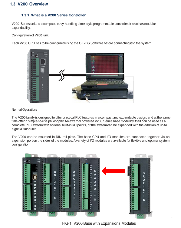
The expansion models include digital expansion (such as GDI216S: 16 digital inputs) and analog expansion (such as GAD208S: 8 analog inputs), supporting flexible configuration of I/O points.
Safety operation standards (top priority)
2.1 Definition of Warning Signs
The document specifies the risk level through "identification+text", and all identification is printed on the equipment body and key positions in the manual:
Core meaning of warning signs Typical scenarios
DANGER operational errors can result in death or serious injury (such as high-voltage electric shock, fire). Opening terminal covers and contacting high-voltage components when powered on
Incorrect operation of Warning may result in serious injury or equipment damage (such as device falling or burning). Handheld terminal cover handling or touching the heat sink
CAUTION operation errors can result in minor injuries or equipment malfunctions (such as loose terminals, electrostatic damage), ungrounded operations, and wiring errors
2.2 Core Security Rules
Prohibited operation list:
Do not open the power terminal cover (which contains 24VDC high-voltage components) when powered on.
Do not insert foreign objects such as wires, tools, dust, etc. into the ventilation openings or terminal slots of the equipment (to prevent short circuits).
It is prohibited to disassemble or modify hardware without authorization (such as replacing non original capacitors), as this will result in warranty failure and safety risks.
It is prohibited to use unverified models in explosion-proof environments (such as flammable gas areas).
Mandatory operation checklist:
Before installation/maintenance, it is necessary to read the manual thoroughly and confirm that the operator is a Qualified Person.
After power failure, wait for at least 15 minutes and use a multimeter with 800Vdc or higher to check that the voltage of the DC main circuit (PA/+and PC/-) is ≤ 45V before operation.
Reliable grounding is required: D-type grounding is used for 240V level, C-type grounding is used for 500/600V level, grounding resistance is ≤ 4 Ω, and the grounding wire specification is not less than the main circuit wire.
When enabling the Auto restart function, a warning label stating 'Possible sudden restart' should be affixed next to the device.
Hardware installation and wiring
3.1 Installation environment requirements
The allowable range of environmental indicators and the prohibited range
Environmental temperature 0 ℃~55 ℃ (operation), -20 ℃~85 ℃ (storage) exceeding 55 ℃ (triggering overheating protection), below -20 ℃ (capacitor failure)
Relative humidity 20%~90% (no condensation) Condensation environment, humidity>90% (causing short circuit)
Vibration requirement ≤ 5.9m/s ² (5-150Hz) exceeding 5.9m/s ² (additional anti vibration pads need to be installed)
Environmental cleanliness without dust, metal powder, corrosive gas, dense dust, and oil mist environment (blocking heat dissipation)
3.2 Wiring specifications
Main circuit wiring:
Power input: 24VDC ± 15%, requires separate wiring (threaded separately from the control circuit), terminal screw torque: M3 is 0.5N · m, M4 is 1.4N · m.
Digital input: 24VDC, current per point 5mA (high-speed input 20mA), input impedance 5.4k Ω (high-speed input 1.2k Ω).
Digital output: Relay type (230V/2A, 30VDC/2A), transistor type (24VDC/0.5A), output terminals need to be wired according to the "set of common terminals every 4 points".
Communication wiring:
RS485: 2-wire system, maximum transmission distance of 1200m, supports 32 nodes, requires 120 Ω terminal resistors to be connected at both ends of the bus.
USB: For programming only, using USB 2.0 Type B interface, cable length ≤ 2m.
Ethernet (GPU200 * 3S): RJ45 interface, supports 10/100Mbps adaptive, requires shielded Ethernet cable.
- OMRON
- ABB
- General Electric
- EMERSON
- Honeywell
- HIMA
- ALSTOM
- Rolls-Royce
- MOTOROLA
- Rockwell
- Siemens
- Woodward
- YOKOGAWA
- FOXBORO
- KOLLMORGEN
- MOOG
- KB
- YAMAHA
- BENDER
- TEKTRONIX
- Westinghouse
- AMAT
- AB
- XYCOM
- Yaskawa
- B&R
- Schneider
- KONGSBERG
- NI
- WATLOW
- ProSoft
- SEW
- ADVANCED
- Reliance
- TRICONEX
- METSO
- MAN
- Advantest
- STUDER
- DANAHER MOTION
- Bently
- Galil
- EATON
- MOLEX
- DEIF
- B&W
- ZYGO
- Aerotech
- DANFOSS
- Beijer
- Moxa
- Rexroth
- Johnson
- WAGO
- TOSHIBA
- BMCM
- SMC
- HITACHI
- HIRSCHMANN
- Application field
- XP POWER
- CTI
- TRICON
- STOBER
- Thinklogical
- Horner Automation
- Meggitt
- Fanuc
- Baldor
- SHINKAWA
- Other Brands
- UniOP
- KUKA
- Iba
- Beckhoff
-
 Basler BE1-25 Time Overcurrent Relay M1FA6PA4S0F
 -
 Basler SR4A2B05B3E Static Voltage Regulator
 -
 Basler DECS-200-2L Digital Excitation Control
 -
 Basler BE303280001 Control Transformer
 -
 Basler 9262103004 Voltage Regulator Board For Basler DECS-400
 -
 Basler ICRM-7 Inrush Current Reduction Module
 -
 Basler BE1-32R Power Relay
 -
 BASLER ELECTRIC KR4F VOLTAGE REGULATOR 9042600100 600V 50/60Hz
 -
 Basler 9222600101 Power Module
 -
 Basler SR8A-2B15B3A Static Voltage Regulator
 -
 BASLER BE1-87G G1E A1L A0N1P Generator Differential Relay w/ Reactor 9170818100
 -
Basler 9284900101 DECS Power Module
-
 Basler PRS250 Veri-Sync Relay
 -
 Basler BE 12296 001 Transformer
 -
 Basler 905970-104 Rev.M Voltage Regulator
 -
Basler BE1-87T Transformer Differential Relay
-
 Basler SR8A-2B15B3A Static Voltage Regulator
 -
 Basler SR32A2B05B3E Static Voltage Regulator
 -
 Basler SR4A-2B16B3A Static Voltage Regulator
 -
 Basler SR32A-2B13B3E Static Voltage Regulator
 -
 Basler KR4F Voltage Regulator 9042600100
 -
 Basler SSR 32-12 Static Voltage Regulator 400Hz
 -
 Basler CBS 212A Current Boost System
 -
 Basler MVC236 Manual Control Module
 -
Basler UFOV Protective Module 9040000100
-
 Basler SSR 125-12 Static Voltage Regulator
 -
 Basler SR4A2B10A3E Static Voltage Regulator
 -
 Basler BE1-25 Solid State Time Overcurrent Relay
 -
 Basler MVC 232 Manual Voltage Control Module
 -
Basler PRS 250 Veri-Sync Relay
-
 Basler UFOV 260A Under Frequency Over Voltage Relay
 -
 Basler RUL2098-10GC Load Relay
 -
 Basler 9 1049 04 100 PC Board
 -
Basler 125-12 Static Voltage Regulator
-
Basler PRS 250 Veri-Sync Relay
-
Basler 9185900102 SSR 125-12 Regulator
-
Basler BE12819001 Reactor
-
 Teradyne 535-100-00 Power Supply
 -
 Basler BE1-67 Directional OC Relay
 -
 Basler PRP110 Reverse Power Relay
 -
 Basler BE30631001 Isolation Transformer
 -
 Basler DECS-200-2L Digital Excitation Control
 -
 Basler BE1-47N Voltage Phase Sequence Relay
 -
 Basler AEC63-7 Analog Excitation Controller 220-277V
 -
Basler BE1-50/51B-107 Overcurrent Relay
-
 Basler Electric BE1‑32R BE1‑E1P‑BON0F Protective Relay
 -
Basler BE1-25 Solid State Time Overcurrent Relay M1EA6PA5S1F
-
 Basler MVC 232 Manual Voltage Control Module 90 37000 103 60VAC 55VDC
 -
Basler RAL6144-16GM Racer GigE Line Scan Camera
-
Basler SSR 63-12 Static Voltage Regulator
-
 Basler BE1-51A Overcurrent Relay
 -
Basler BE1-87T Solid State Protective Relay
-
Basler SR4A2B01B3A Static Voltage Regulator
-
 Basler SSR 32-12 Static Voltage Regulator
 -
 Basler TRR00696 Transformer 1KVA 115V
 -
 Basler DECS-100-B15 AVR Replacement
 -
Basler BE1-27 Under-Voltage Relay
-
 Basler ACA2000-50GM Interface Module
 -
 Basler AEC63-7 Analog Excitation Controller
 -
Basler PRS 250 Veri-Sync Relay
-
 Basler SR4A-2B15B3A Static Voltage Regulator
 -
Basler BE1-32R Power Relay
-
Basler SR8A-2B06B3E Static Voltage Regulator
-
Basler BE1-81 O/U Frequency Relay
-
 Basler BE1-51A-K2E-W6M-B1N0F Overcurrent Relay
 -
Basler BE1-851 Overcurrent Relay G3A1S1 – 48-125V AC/DC
-
 Basler BEI-51 Overcurrent Relay – NSN 5945-01-293-2363
 -
Basler Electric L301KC Protective Relay – L301KC
-
 Basler DECS-100-B15 Automatic Voltage Regulator – Generator AVR
 -
Basler SR4A-2B15B3A Static Voltage Regulator – SR4A2B15B3A
-
Basler UF 312 Under Frequency Protective Module – 9094700100
-
Basler Electric MVC 232 Manual Control Module – 60VAC 55VDC 20A
-
Basler PRS 250 Veri-Sync Relay – Generator Synchronizing Relay
-
 Basler DECS-100-A05 Digital Regulator Review
 -
 Basler AEM-2020 Analog Expansion Module Specs
 -
 Basler DECS-100-B15 Digital Excitation Specs
 -
Basler Electric 9125600106 Regulator Component
-
Basler BE1-51A-K1E-W6M-B1N0F Overcurrent Relay
-
 Basler MVC-301 MVC 300 Excitation Controller
 -
Basler SSR 32-12 Static Voltage Regulator
-
Basler 9-2849-00-101 Control Module
-
Basler BE1-51A Overcurrent Relay
-
 Basler BE1-51/27R Overcurrent Relay
 -
 Basler BE1-51 Overcurrent Relay
 -
 Basler SR8A-2B15B3A Static Voltage Regulator
 -
 Basler BE32965001 Transformer and Timer Board
 -
 Basler 9174700100 EL200-7 Excitation Limiter
 -
 Basler BE2000E AVR Voltage Regulator
 -
Basler BE1-87G Differential Relay
-
 Basler BE21834001 Generator Control Module
 -
Basler DECS-100-B15 AVR
-
 Basler D90 96801 100 PCB Card
 -
 Basler XR2002F Voltage Regulator (110 VAC, 48-480 Hz)
 -
 Basler SR8A-2B14B3A Regulator
 -
 Basler 9561500100 Module
 -
 Basler DECS-400 BE1-11 System
 -
 Basler DECS-100-B15 Excitation Control
 -
Basler SCP 210 Frequency Controller
-
Basler SR4A-2B15B3A Static Voltage Regulator
-
Basler BE1-32R Power Relay
-
 Basler PIA2400-17GM Power Interface Adapter
 -
 Basler MVC 232 Manual Voltage Control Module
 -
Basler SSR 32-12 Static Voltage Regulator
-
Basler 5MW AVR Generator Voltage Regulator
-
 Basler VR63-4B Voltage Regulator
 -
Basler DECS-100-A05 AVR for Engine Generator
-
Basler DECS-100-B15 Automatic Voltage Regulator
-
Basler BE1-32R Directional Power Relay
-
Basler BE1-87B Differential Relay
-
 Basler UFOV 260A Protective Module
 -
 Basler 9-2614-02-100 PCB Rev M
 -
Basler DECS-100-B15 Digital AVR
-
 Basler 9284900103 PS DECS-400N
 -
 Basler D4N3H1U Intertie Protection
 -
 Basler DECS-100-B15 A15 AVR
 -
 Basler KR4F Voltage Regulator
 -
 Basler BE26434 T14 Transformer
 -
 Basler SR8A-2B15B3A Regulator
 -
 Westinghouse 774B472A12 AR Relay
 -
Basler DECS-100-B15 AVR
-
Basler XR2002F Regulator 110V
-
Basler SR125-E Static Regulator
-
Basler SSR 125-12 Regulator
-
Basler MOC2599 Motor Pot
-
 Basler BE1-DFPR Feeder Relay
 -
 Basler CBS 305 Current Boost
 -
Basler BE1-25 AutoSync
-
Basler MVC 300 Voltage Control


