
TOSHIBA TOSBERT VF-S15 series frequency converter
TOSHIBA TOSBERT VF-S15 series frequency converter
1. Core positioning and scope of application of the document
1.1 Document positioning
This document is the official complete manual for the TOSBERT VF-S15 series frequency converter released by Toshiba Industrial Products and Systems Corporation. It includes five core functions: installation guidance, operation tutorial, parameter configuration manual, troubleshooting guide, and maintenance specification. It is an essential technical document for the entire life cycle of the equipment from unboxing to scrapping. All information may be updated without notice, and the latest version must be obtained through the official website.
1.2 Core Product Parameters
1.2.1 Model and Power Coverage
Voltage level, phase, power range, core application scenarios
240V level 3-phase 0.4kW -15kW universal industrial three-phase motor speed regulation
240V level 1-phase 0.2kW -2.2kW small single-phase power supply drives three-phase motor
500V level 3-phase 0.4kW -15kW medium and high voltage industrial equipment (such as pumps and fans)
600V 3-phase 1.5kW -15kW High Voltage Industrial Production Line Motor Control
1.2.2 Applicable motor types
Core Adaptation: Three phase induction motors, built-in permanent magnet synchronous motors (IPMSMs), surface permanent magnet synchronous motors (SPMSMs) (for general industrial scenarios only).
Explicitly prohibited: single-phase motors (unable to be driven by frequency converters), special motors (such as high-speed motors and high slip motors requiring special parameter configuration).
1.2.3 Prohibited application scenarios
High risk public areas: scenarios such as power plants, railways, and public transportation that may have significant public impacts.
Life safety related: nuclear power equipment, aerospace equipment, medical surgical equipment, life support systems, and other equipment that may directly endanger life due to malfunctions.
Special quality requirements: Equipment that requires dedicated quality control or special warranty terms (if needed, contact Toshiba in advance to assess compatibility).
2. Safety precautions (top priority)
2.1 Warning Signs and Definitions
The document specifies the risk level through "identification+text description", and all identification is printed on the inverter body and key positions in the manual:
Core meaning of warning signs Typical applicable scenarios
Warning operation errors can directly lead to death or serious injury (such as electric shock, fire, serious injury). Disassembling the frequency converter, opening the terminal cover when powered on, and contacting high-voltage components
CAUTION operation errors can result in minor injuries (without hospitalization/long-term outpatient treatment), such as burns, mild electric shocks, pinch injuries touching the heat sink, holding terminal covers during transportation, and scratching hands when disassembling and assembling terminals
NOTICE operation errors can lead to property damage (equipment failure, material loss, etc.), improper wiring can cause the frequency converter to burn out, and improper environment can lead to equipment failure
2.2 Absolute prohibition of operation (zero tolerance clause)
Disassembly, modification, and maintenance are prohibited: The frequency converter contains high-voltage components and precision electronic components inside. Disassembling it without authorization may cause electric shock and fire. Any malfunctions should be handled by contacting an authorized Toshiba dealer.
Do not open the terminal cover when powered on: The power circuit terminal cover covers the high-voltage area, and opening it while powered on will directly expose the high voltage, causing electric shock accidents.
Prohibited foreign object intrusion: It is forbidden to insert fingers, wires, tools, etc. into the wiring holes of the frequency converter, the openings of the cooling fan cover, etc., to avoid short circuits, electric shocks, or equipment damage.
Prohibited liquid contact: Do not allow water, oil, chemical liquids, etc. to come into contact with the frequency converter, otherwise it may cause short circuit, electric shock, and fire.
Do not connect the power supply in reverse: Do not connect the power supply to the output terminals (U/T1, V/T2, W/T3), and do not connect the braking resistor between the DC terminals (PA/+and PC/- or PO and PC/-), otherwise it will burn the frequency converter and cause a fire.
Prohibition of driving motors in violation of regulations: It is prohibited to use this frequency converter to drive single-phase motors or motors exceeding the adapted power (such as small capacity frequency converters driving large capacity motors).
Prohibit direct use of IT systems: When the frequency converter is connected to the IT system power supply (ground isolation or high impedance grounding), the grounding capacitor must be disconnected, otherwise it may cause faults or fires.
2.3 Mandatory Execution Operation (must be followed)
Manual management requirements: The manual must be delivered to the end user, read thoroughly before installation/operation, and stored in a safe and easily accessible location for future reference.
Power off operation specifications: Before wiring, maintenance, and terminal disassembly, it is necessary to: ① turn off all input power sources; ② Wait for at least 15 minutes (to discharge the capacitor); ③ Use a multimeter with a range of 800Vdc or higher to confirm that the DC main circuit voltage (between PA/+and PC/-) is ≤ 45V; ④ The PM motor needs to be additionally confirmed to have completely stopped (high voltage will be generated at the output terminal during rotation).
Grounding requirements: The grounding wire must be of the same or larger specification as the main circuit wire, firmly connected (240V level is D-type grounding, 500V/600V level is C-type grounding), and the grounding resistance must comply with local safety standards. Improper grounding may cause electric shock in case of equipment failure.
Installation of emergency stop device: An emergency stop device that meets the system specifications (such as mechanical braking) must be installed. Emergency stop cannot be achieved solely by the frequency converter, and failure to install it may result in accidents.
Terminal screw tightening: All terminal screws must be tightened to the specified torque (such as 1.0N · m for M3.5 and 2.4N · m for M5). Insufficient torque can cause poor contact, heat generation, and fire hazards.
Power supply voltage verification: The power supply voltage must be within the range of+10% to -15% of the voltage indicated on the nameplate (± 10% when running continuously under 100% load). Exceeding this range may cause equipment failure or fire.
Warning label pasting: When enabling the Auto restart or retry function, prominent warning labels must be pasted on the frequency converter, motor, and equipment, indicating that "the equipment may suddenly restart, do not approach".
3. Detailed specifications for installation and connection
3.1 Transportation and unboxing inspection
3.1.1 Transportation taboos
It is prohibited to handle the power circuit terminal cover by hand. The terminal cover may fall off, causing equipment damage or personal injury.
During transportation, it is necessary to ensure that the terminal cover is installed in place and avoid reaching hands into the wiring holes or heat dissipation ports to prevent pinching or scratching.
Do not stack heavy objects during transportation to avoid squeezing the inverter casing and heat sink.
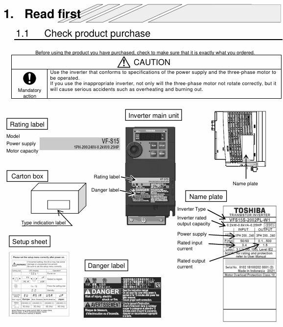
3.1.2 Open box inspection items
Appearance inspection: The shell is not damaged or deformed, the heat sink is not bent, and the terminals are not oxidized or loose.
Accessory inspection: The inverter host, quick start manual, multilingual warning label kit, CD-ROM (electronic manual), and installation accessories (screws, washers) are complete.
Nameplate verification: The parameters such as model, voltage level, rated power, and rated current are consistent with the order.
3.2 Installation environment requirements
3.2.1 Environmental Parameters
The allowable range of environmental indicators and the prohibited range
Ambient temperature -10 ° C~60 ° C Exceeding 60 ° C (triggers overheat protection), below -10 ° C (capacitor failure)
Relative humidity 20%~90% (no condensation) Condensation environment, humidity exceeding 90% (can cause short circuit)
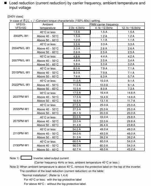
There is no clear upper limit for altitude ≤ 1000m (for altitudes above 1000m, capacity reduction is required), but capacity reduction of 10% is required for every 1000m increase in altitude
Vibration requirement ≤ 5.9m/s ² (5-150Hz) exceeding 5.9m/s ² (additional anti vibration pad required)
Environmental cleanliness: no dust, metal powder, oil mist, corrosive gas, dense dust, corrosive gas, oil mist environment
3.2.2 Installation Space Requirements
Single installation: A space of ≥ 5cm should be reserved at the top, bottom, and both sides to ensure heat dissipation and ventilation.
Multiple parallel installations: When the distance between adjacent frequency converters is ≥ 3cm and the ambient temperature exceeds 40 ° C, the top protective label needs to be removed and additional ventilation measures need to be taken.
Cabinet installation: The cabinet needs to reserve sufficient ventilation openings or install cooling fans to ensure that the temperature inside the cabinet does not exceed the upper limit of ambient temperature allowed by the frequency converter; The frequency converter should be installed above the interior of the cabinet to avoid the accumulation of hot air.
3.3 Detailed wiring specifications
3.3.1 Main circuit wiring (core link)
3.3.1.1 Terminal Definition and Function
Terminal symbol function description, wiring precautions
Connect the R/L1, S/L2, T/L3 3-phase power input terminals correctly according to the phase and do not connect them in reverse; The 1-phase model only uses R/L1, S/L2/N, without T/L3 terminals
The output terminals of U/T1, V/T2, and W/T3 motors are connected to the three-phase windings of the motor, and phase errors can cause the motor to reverse; Do not connect power input
PA/+, PC/- internal DC main circuit terminals (positive and negative) can be connected to the DC common power supply; Do not directly connect the braking resistor
The PB brake resistor connection terminal should be connected to the brake resistor according to the specified specifications in the manual, and the wrong terminal should not be connected
The connection terminal of PO DC reactor (DCL) is short circuited with PA/+when it leaves the factory. Before installing the DC reactor, the short circuiting piece needs to be removed
The grounding terminal (⊕) of the equipment must be reliably grounded, with at least one grounding terminal connected. It is recommended to connect all available grounding terminals
3.3.1.2 Wiring Materials and Specifications
Main circuit wire: Copper core wire is required, and the specifications should be selected according to the rated current of the frequency converter (refer to the table in section 10.1). For example, 1.0mm ² wire is recommended for the 0.4kW 240V model.
Control circuit wire: 0.3-1.5mm ² twisted wire (single stranded wire requires a wire nose), with a stripping length of 6mm to avoid short circuits caused by long exposed wires.
Grounding wire: Specification ≥ main circuit wire, recommended to use yellow green dual color wire, grounding resistance ≤ 4 Ω (adjusted according to local standards).
3.3.1.3 Wiring taboos
The wires of the main circuit and control circuit are prohibited from being laid in the same pipe, parallel or bundled together to avoid interference.
Wire length: The length of the main circuit wire is ≤ 30m, and if it exceeds 30m, the wire specification needs to be increased; If the length of the control circuit wire is ≤ 5m, shielded wire should be used, and one end of the shielding layer should be grounded.
It is prohibited to install power factor correction capacitors and noise suppression filters on the output side of the frequency converter (except for Toshiba's recommended motor end surge voltage suppression filter), otherwise it may cause frequency converter failure or fire.
3.3.2 Control Circuit Wiring
3.3.2.1 Terminal Layout and Function
The control circuit terminal block is universal for all models, and the core terminal functions are as follows:
Terminal symbol input/output core functional electrical specifications
F. Input forward (F) and reverse (R) commands, default short circuit F-CC (Sink logic) or P24-F (Source logic) to start no voltage logic input, 24Vdc, below 5mA
RES input fault reset, short circuit RES-CC or P24-RES reset, under normal conditions, short circuit is invalid and shares logic with F and R (Sink/Source can be switched through SW1)
S1, S2, S3 input preset speed command input, S2 can be set as pulse sequence input through f146, S3 can be set as PTC input through SW2, pulse sequence input: 10pps~2kpps, duty cycle 50 ± 10%
VIA and VIB input analog frequency command input, default 0-10VDC; VIB can be set to -10~+10Vdc with an input impedance of 30k Ω and a resolution of 1/1000 through f107
VIC input analog current command input, default 4-20mAdc (can be set to 0-20mAdc) input impedance 250 Ω
FM output analog signal output (such as frequency, current), can be set to 0-1mA, 0-20mA, 0-10VDC through f681 load resistance: current output ≤ 600 Ω, voltage output ≥ 1k Ω
FLA, FLB, FLC output relay contact output, default detection protection function action (FLA-FLC closed and FLB-FLC disconnected during protection action) Maximum switching capacity: 250Vac-2A, 30Vdc-2A (resistive load)
RY and RC output relay contact output, default low-speed signal output 30Vdc-1A, minimum load 5Vdc-100mA
RS485 input/output communication interface, supports RS485 communication 2-wire interface, requires matching terminal resistance
3.3.2.2 Logical Switching (SW1, SW2)
SW1 (Sink/Source Switching): By default, switch the logic types of F, R, RES, S1-S3 on the PLC side. Sink logic shares the CC terminal, while Source logic shares the P24 terminal.
SW2 (VIB/S4, S3/PTC switching): The upper SW2 switches VIB to analog input (VIB side) or logic input (S4 side); Switching S3 to logic input (S3 side) or PTC input (PTC side) on the lower side of SW2 requires coordination with parameters f109 and f147.
3.3.3 Grounding capacitor switch operation
Applicable models: 1-phase 240V models (VFS15S-2002PL-W1~2022PL-W1), 3-phase 500V models (VFS15-4004PL-W1~4150PL-W1).
Function: Switch the grounding capacitor capacity, default to "large" capacity (factory setting), pull the switch to change to "small" capacity, reduce leakage current.
Key requirement: When connecting the IT system power supply, it must be switched to a "small" capacity (disconnect the grounding capacitor); After switching the 4037PL-W1 model, the f300 (PWM carrier frequency) should be set to 4kHz or below, and the motor cable length should be ≤ 30m.
3.4 Inspection after installation
Wiring recheck: The terminal wiring is not loose, misconnected, or missed, and there is no cross interference between the main circuit and control circuit wires.
Insulation inspection: Use a multimeter to check the insulation of the main circuit to ground, and there is no short circuit phenomenon.
Mechanical inspection: The frequency converter is firmly fixed and not loose; The heat sink is unobstructed and the ventilation channel is unobstructed.
4. Detailed explanation of operation and parameter settings
4.1 Operation panel functions and basic operations
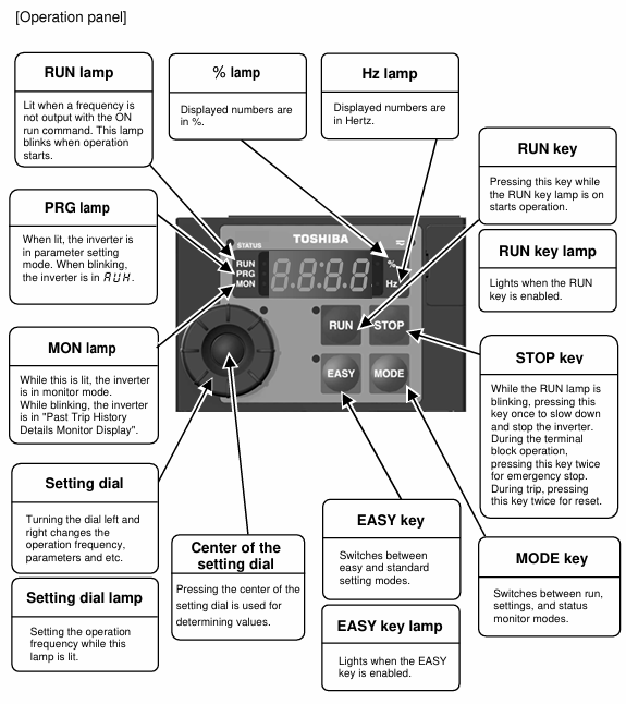
4.1.1 Operation panel layout and button functions
Component Name Function Description
Display screen with 4-digit LED, capable of displaying frequency, parameters, fault codes, monitoring data, etc., supporting numerical and alphabetical display
Run button, press the start motor when the RUN button light is on
STOP key: Press once to slow down and stop during operation; Press the emergency stop button twice during terminal operation; Reset twice in case of malfunction
MODE key mode switch, switch between standard monitoring, parameter settings, and status monitoring modes
EASY key for switching between simple/standard settings mode. When the EASY key light is on, it enters the simple mode (displaying only commonly used parameters)
Set the parameter values and frequency for adjusting the left and right rotation of dialing; Press to confirm settings
When the Hz light is on, the display screen shows the frequency (Hz)
%When the light is on, the display screen shows the percentage (such as load rate)
When the RUN light flashes, it indicates that the motor is running, and when it is constantly on, it indicates that the RUN button is valid
When the PRG light is on, it indicates the parameter setting mode, and when it flashes, it indicates automatic tuning is in progress
When the MON light is on, it indicates the status monitoring mode, and when it flashes, it indicates the monitoring of fault history details
The STATUS light lights up or flashes during CANopen communication
When the Charge light is on, it indicates that there is still high voltage inside the inverter, and it is forbidden to open the terminal cover
4.1.2 Basic operation process
4.1.2.1 Panel operation (default mode, cmod=1)
Power on: The Charge light will turn on and then turn off, and the display screen will show "0.0" (default output frequency).
Frequency setting: Rotate the setting dial and adjust it to the target frequency (such as 50Hz). When fmod=0, there is no need to confirm (power off and save); When fmod=3, press the set dialing confirmation button (flash and save).
Start motor: Press the RUN button, the RUN light flashes, the motor starts according to the set acceleration time, and the display screen shows the real-time output frequency.
Stop motor: Press the STOP button to stop the motor according to the set deceleration time, and the display screen returns to "0.0".
4.1.2.2 Terminal operation (cmod=0)
Parameter settings: Set cmod to 0 (terminal block command mode) and fmod to the corresponding input method (e.g. 1=VIA terminal).
Wiring: Connect the forward (F), reverse (R), and common (CC) terminals (Sink logic) according to the standard connection diagram.
Start: Short circuit F-CC, motor starts; Disconnect F-CC, the motor decelerates and stops.
Emergency stop: Press the STOP button on the panel twice or trigger the external emergency stop device.
4.2 Parameter Setting Core System
4.2.1 Classification of Parameter Modes
Easy setting mode: The EASY key light is on, displaying only 10 commonly used parameters (such as cmod, fmod, acc, dec, ul, ll, etc.), and up to 32 parameters can be custom registered through f751-f782.
Standard setting mode: EASY key light off, displaying all basic and extended parameters (thousands in total), classified by function (such as frequency parameters, protection parameters, communication parameters).
Parameter protection: Parameter protection can be set through f700 (0=allow read/write, 1=prohibit panel writing, 2=prohibit communication writing), or password can be set through f738 (1-9998) to prevent misoperation.
4.2.2 Detailed Explanation of Core Parameters (Classified by Function)
4.2.2.1 Frequency related parameters
Parameter Name Parameter Symbol Adjustment Range Default Value Function Description
The maximum frequency fh is between 30.0-500.0Hz and 80.0Hz, which is the upper limit of the output frequency of the frequency converter and serves as a reference for acceleration/deceleration time
The upper limit frequency ul 0.5-fh (Hz) is the maximum limit of the actual output frequency of the setup menu and cannot exceed fh
The lower limit frequency ll 0.0-ul (Hz) is the lowest limit of the actual output frequency, below which the motor stops
The basic frequency of 1 vl 20.0-500.0Hz is determined by the rated frequency of the setup menu motor (such as 50Hz, 60Hz), which determines the constant torque control area
The basic frequency voltage is 1 vlv 50-330V (240V level), and the output voltage corresponding to the basic frequency of the setup menu needs to match the rated voltage of the motor
Jump frequency 1-3 f270-f272 0.0-fh (Hz) is a frequency point to avoid mechanical resonance, such as f270=50Hz and f271=2Hz (jump width)
Starting frequency f240 0.1-10.0Hz 0.5Hz is the instantaneous output frequency during startup to avoid torque delay. It is recommended to use 0.5-3.0Hz
4.2.2.2 Acceleration/deceleration related parameters
Parameter Name Parameter Symbol Adjustment Range Default Value Function Description
Acceleration time 1 acc 0.0-3600s 10.0s Acceleration time from 0Hz to fh
Deceleration time 1 dec 0.0-3600s 10.0s Deceleration time from fh to 0Hz
Acceleration/deceleration time unit f519 0=default, 1=0.01s, 2=0.1s 0 Switching time adjustment accuracy, such as ACC can be set to 0.01s when f519=1
Automatic acceleration/deceleration au1 0=disabled, 1=automatic, 2=only accelerating automatic 0. Automatically adjust acceleration/deceleration time according to load to avoid overcurrent and overvoltage
Acceleration/deceleration mode 1 f502 0=linear, 1=S mode 1, 2=S mode 2 0. Linear mode is universal, S mode 1 is suitable for fast acceleration, and S mode 2 is suitable for high-speed spindles
The second acceleration time f500 0.0-3600s 10.0s can be switched through the terminal for the second set of acceleration times
The second deceleration time f501 is 0.0-3600s and 10.0s, which can be switched through the terminal for the second set of deceleration times
4.2.2.3 Motor protection parameters
Parameter Name Parameter Symbol Adjustment Range Default Value Function Description
Electronic thermal protection level 1 thr 10-100% (or A) 100% is based on the rated current of the frequency converter and needs to be adjusted according to the rated current of the motor (for example, if the rated current of the motor is 42% of the frequency converter, set it as 42%)
Electronic thermal protection level 2 f173 10-100% (or A) 100% second group electronic thermal protection level, which can be switched through terminals
Overload characteristic selection: aul 0=default, 1=constant torque, 2=variable torque 0 1=150% -60s (applicable to conveyors), 2=120% -60s (applicable to fans and pumps)
Electronic thermal memory f632 0=disabled, 1=enabled, 0. Save the accumulated overload value after power failure, and continue calculation after power on
Overload alarm level f657 10-100%. When 50% overload reaches this level, a flashing alarm will sound, and an alarm signal can be output through the output terminal
Motor 150% overload detection time f607 10-2400s 300s When the motor current reaches 150%, delay the time and trip
Stall protection level 1 f601 10-199% (or A), 200=disable 150% overcurrent stall protection threshold, automatic frequency reduction when exceeding this value
4.2.2.4 Special functional parameters
Parameter Name Parameter Symbol Adjustment Range Default Value Function Description
Automatic restart control f301 0=disabled, 1=instantaneous power outage restart, 2=ST terminal control 0 1=detect motor speed after instantaneous power outage, smooth restart after power restoration
The retry count f303 0=disabled, 1-10 times 0. Automatic retry after overcurrent, overvoltage, etc. tripping, retry interval increases from 1s to 10s
Dynamic braking selection f304 0=disabled, 1=enabled (resistance protection), 2=enabled. After enabling 0, the braking resistor needs to be connected for rapid deceleration or regenerative load scenarios
The resistance value of the braking resistor f308 1.0-1000 Ω should be consistent with the actual resistance value of the connected braking resistor depending on the model
Overvoltage limit operation f305 0=enabled, 1=disabled, 2=rapid deceleration, 2=automatic frequency adjustment when DC voltage is too high during deceleration to avoid overvoltage tripping
PID control selection f360 0=disabled, 1=process type, 2=speed type 0 is used for closed-loop control of flow, pressure, etc., and feedback signals (such as 4-20mA at VIC terminal) need to be coordinated
The PID setpoint fpid f368-f367 (Hz) is the target value of the 0.0Hz PID control, which can be adjusted through the panel or communication
4.3 Parameter Setting Operation Steps (Taking Adjusting Thr as an Example)
Switching mode: Press the MODE key, the display screen will show "auh" (history function), rotate the setting dial to select "thr".
Read current value: Press the set dial button, and the display screen will show the current value (such as 100%).
Adjust parameters: Rotate the dial setting to the target value (such as 42%).
Confirm save: Press the set dial button, and the display screen will alternately show "42" and "thr", indicating successful save.
Return to monitoring: Press the MODE button twice to return to standard monitoring mode (display output frequency).
4.4 Example of Common Operating Mode Configuration
4.4.1 Panel operation+setting dialing frequency (default configuration)
Cmod=1 (panel command mode)
Fmod=0 (set dial 1, power off and save)
Operation: Rotate to set the dialing frequency, press RUN to start, press STOP to stop.
4.4.2 Terminal operation+external potentiometer frequency
CMOD=0 (Terminal Command Mode)
Fmod=1 (VIA terminal input)
Wiring: VIA-CC indirect external potentiometer (1k-10k Ω)
Operation: Short circuit F-CC starts, disconnect F-CC stops, adjust potentiometer to change frequency.
4.4.3 Preset speed operation (3-speed)
CMOD=0 (Terminal Command Mode)
Fmod=14 (sr0 preset speed)
Parameter settings: sr1=20Hz, sr2=30Hz, sr3=50Hz (set 3-stage speed)
Wiring: S1-CC (speed 1), S2-CC (speed 2), S3-CC (speed 3)
Operation: Short circuit corresponding terminal selection speed, short circuit F-CC starts.
5. Monitoring and fault handling
5.1 Status monitoring function
5.1.1 Standard Monitoring Mode
Default display: Output frequency (f710=0), can be switched through f710 to display: output current (1), frequency command value (2), input voltage (3), output voltage (4), torque (7), etc.
Peak/minimum monitoring: f709=1 (peak hold), f709=2 (minimum hold), triggered by EASY key (f750=3) for measurement.
5.1.2 Status Monitoring Mode
Entry method: Press the MODE button twice, and the MON light will turn on.
Monitoring content: frequency command value, output current, output voltage, terminal input status, terminal output status, PID feedback value, overload rate, etc. Multiple monitoring items are supported and can be switched through dial-up settings.
5.1.3 Fault History Monitoring
Entry method: When the MON light flashes, enter to view the fault codes, frequency, current, voltage, and other data of the last 8 trips.
5.2 Common Fault Codes and Handling
5.2.1 Overcurrent faults (oc1, oc2, oc3)
Fault cause: ① Motor short circuit, grounding; ② Excessive load; ③ The acceleration time is too short; ④ Terminal wiring error; ⑤ Internal malfunction of the frequency converter.
Processing steps:
Power off and check the insulation of the motor winding, eliminate short circuits and grounding faults.
Check if the load is stuck, clean any foreign objects, and ensure that the load is within the rated range.
Increase the acceleration time (acc) or enable automatic acceleration (au1=1).
Recheck the wiring of the main circuit terminals to ensure there are no misconnections or looseness.
If all of the above are normal, contact a Toshiba dealer to inspect the internal of the frequency converter.
5.2.2 Overvoltage faults (op1, op2, op3)
Fault cause: ① High power supply voltage; ② The deceleration time is too short; ③ Excessive regeneration load; ④ Braking resistor not connected or faulty; ⑤ Overvoltage limit operation disabled.
Processing steps:
Measure the power supply voltage and confirm that it is within the rated range (+10%~-15%).
Increase deceleration time (dec) or enable overvoltage limit operation (f305=0).
Check if the brake resistor connection is correct and if the resistance value meets the requirements.
In scenarios with large regenerative loads (such as crane lowering), larger capacity braking resistors need to be replaced.
5.2.3 Overload fault (ol1, ol2, ol3)
Fault cause: ① The rated current of the motor does not match the THR; ② The load exceeds the rated value for a long time; ③ Error in setting electronic thermal protection characteristics; ④ Poor heat dissipation of the motor.
Processing steps:
Check the rated current of the motor and adjust the Thr parameter (e.g. if the rated current of the motor is 50% of the frequency converter, set Thr to 50%).
Check if the load is overloaded, reduce the load or replace the motor with a higher power.
Confirm that the aul parameters match the motor type (constant torque load set aul=1).
Check if the motor cooling fan is working properly and clean the dust on the cooling fins.
5.2.4 Overheating Fault (oh)
Fault cause: ① Excessive ambient temperature; ② Blockage of heat sink; ③ Cooling fan malfunction; ④ PWM carrier frequency is too high; ⑤ The frequency converter is running under overload.
Processing steps:
Improve ventilation environment and reduce ambient temperature (ensure ≤ 60 ° C).
Clean the dust and debris from the heat sink to ensure that the heat dissipation channel is unobstructed.
Check if the cooling fan is running, and replace the fan if there is a malfunction.
Reduce the PWM carrier frequency (f300, such as from 12kHz to 8kHz).
Check for long-term overload operation, adjust the load or increase the capacity of the frequency converter.
5.3 Fault reset method
Manual reset: After troubleshooting, press the STOP button on the panel twice or short-circuit the RES-CC terminal (Sink logic) for more than 1 second.
Automatic reset: Enable the retry function (f303=1-10), and the frequency converter will automatically retry starting after troubleshooting.
Attention: Before resetting, it is necessary to confirm that the cause of the fault has been eliminated and the operation command has been turned off to avoid accidents caused by sudden motor start-up.

6. Maintenance and upkeep standards
6.1 Maintenance Classification and Cycle
6.1.1 Daily Inspection (Daily)
Appearance inspection: There are no abnormal sounds or odors, and the shell is not overheated (can be touched by hand, no overheating phenomenon).
Running status: There are no fault codes on the display screen, and the indicator lights are in normal condition (such as RUN light, Charge light).
Environmental inspection: The ambient temperature and humidity are within the allowable range, and there is no accumulation of dust or oil mist.
6.1.2 Regular inspection (every 6 months)
Cleaning: Use compressed air (pressure ≤ 0.3MPa) to clean the dust on the heat sink and cooling fan. Do not clean with water or chemical solvents.
Wiring inspection: All terminal screws should be tightened to the specified torque, and the insulation layer of the wire should be checked for aging or damage.
Fan inspection: There is no abnormal noise when the cooling fan is running, and the air volume is normal. If the fan speed decreases or there is abnormal noise, it needs to be replaced.
Capacitor inspection: Observe the appearance of the capacitor for any bulges or leaks. If any are found, replace it immediately.
6.1.3 Annual Inspection (Every Year)
Insulation test: After power failure, use a 500V megohmmeter to test the insulation resistance of the main circuit to ground, which should be ≥ 1M Ω.
Parameter backup: Backup the current parameter settings (through the panel or communication tool) to prevent parameter loss.
Component lifespan inspection: Based on accumulated operating time and ambient temperature, check the lifespan of vulnerable parts such as capacitors and fans, and replace them in advance if they are close to their lifespan.
6.2 Specification for Replacement of Vulnerable Parts
6.2.1 Cooling fan
Replacement cycle: The cumulative operating time is about 20000 hours (or 2 years), and the cycle will be shortened if the ambient temperature is high.
Replacement note: Toshiba designated model fan must be used. Before replacement, power off and wait for the capacitor to discharge. After installation, test that the fan runs normally.
After replacement, set typ=9 and reset the accumulated running time of the fan to zero.
6.2.2 Capacitors (main circuit capacitors, control circuit capacitors)
Replacement cycle: The cumulative operating time is about 50000 hours (or 5 years), and it is shortened to 3 years when the ambient temperature exceeds 40 ° C.
Replacement precautions: Capacitors of the same specifications and capacity must be used. When replacing, discharge them thoroughly to avoid electric shock; After replacement, it is necessary to check the correct polarity of the capacitor.
6.2.3 Terminals and Wires
Replacement cycle: Replace immediately if insulation aging or terminal oxidation is found in the wire.
Replacement precautions: The wire specifications should be consistent with the original specifications, and the terminals should be securely crimped and tightened to the specified torque.
6.3 Storage Specifications
Storage environment: Temperature -20 ° C~60 ° C, humidity 20%~90% (no condensation), no dust or corrosive gases.
Storage period: Long term storage (over 6 months) requires power on every 6 months for 30 minutes each time to prevent capacitor failure.
Preparation before storage: Clean the equipment of dust, disconnect all external wiring, package well to prevent moisture and collision.
6.4 Disposal of Waste
Disposal requirements: Frequency converters belong to industrial waste and must be disposed of by professional industrial waste disposal institutions (such as industrial waste collectors and transporters). Disassembly by oneself is prohibited.
Preparation before disposal: Disconnect all power sources, discharge fully, remove the grounding wire, ensure that there is no residual voltage in the capacitor, and prevent capacitor explosion or harmful gas production during disassembly.
Compliance requirements: Comply with local laws and regulations related to industrial waste disposal.
7. Appendix and Supplementary Information
7.1 Compliance Standards
CE certification: Complies with CE directive requirements, requires installation of EMC board and shielding wire according to manual requirements to ensure electromagnetic compatibility.
UL/CSA standards: Complies with UL and CSA safety standards, input voltage ≤ 480V (500V level), and requires the use of specified wiring materials.
ATEX certification: Some models comply with ATEX standards and are suitable for explosion-proof environments, requiring installation according to relevant specifications.
7.2 Common Accessories and Options
Braking resistor: PBR series (such as PBR-2007 120W-200 Ω), to be selected according to the frequency converter model and load.
Reactor: Input Reactor (ACL), DC Reactor (DCL), used to improve input power factor and suppress harmonics.
Communication accessories: USB communication conversion unit (USB001Z), parameter writer (RKP002Z), expansion panel (RKP007Z).
Filter: Motor end surge voltage suppression filter (MSF series), used in long cable scenarios (over 30m).
- OMRON
- ABB
- General Electric
- EMERSON
- Honeywell
- HIMA
- ALSTOM
- Rolls-Royce
- MOTOROLA
- Rockwell
- Siemens
- Woodward
- YOKOGAWA
- FOXBORO
- KOLLMORGEN
- MOOG
- KB
- YAMAHA
- BENDER
- TEKTRONIX
- Westinghouse
- AMAT
- AB
- XYCOM
- Yaskawa
- B&R
- Schneider
- KONGSBERG
- NI
- WATLOW
- ProSoft
- SEW
- ADVANCED
- Reliance
- TRICONEX
- METSO
- MAN
- Advantest
- STUDER
- DANAHER MOTION
- Bently
- Galil
- EATON
- MOLEX
- DEIF
- B&W
- ZYGO
- Aerotech
- DANFOSS
- Beijer
- Moxa
- Rexroth
- Johnson
- WAGO
- TOSHIBA
- BMCM
- SMC
- HITACHI
- HIRSCHMANN
- Application field
- XP POWER
- CTI
- TRICON
- STOBER
- Thinklogical
- Horner Automation
- Meggitt
- Fanuc
- Baldor
- SHINKAWA
- Other Brands
- UniOP
- KUKA
- Iba
- Beckhoff
-
 Basler Electric Phase Directional Overcurrent Relay BE1-Z2JA0N2F
 -
 Basler SSR125-12 Static Voltage Regulator
 -
 Basler Electric KR7F VOLTAGE REGULATOR 9116200100
 -
 BASLER ELECTRIC BE1-59N-A8E-E1L-N0S1F Ground Overvoltage Relay
 -
 Basler SR8A2B06B3A Static Voltage Regulator
 -
 BASLER ELECTRIC BE1-81O/UT3EE1KA7N1F Under/Over Frequency Relay
 -
 Basler MOC2107 Output Module
 -
 Basler 9125600102 Control Module
 -
 BASLER ELECTRIC BE1-81T1EE1EA2N0F
 -
 Basler BE3-25A Time Overcurrent Relay
 -
 Basler Electric CBS 212 Current Boost System 9 2650 00 100 120/240 VAC 50/60Hz
 -
Basler Electric BE1-27 Under Voltage Relay A3EC1JA0N5F
-
 Basler BE1-32R Power Relay B2EE1PA0N1F
 -
 Basler DECS100-B15 Automatic Voltage Regulator
 -
 Basler SR8A-2B15B3A Static Voltage Regulator
 -
 Basler AVC63-4 Analog Voltage Regulator
 -
 Basler UFOV 260 A Overvoltage Module
 -
 Basler SR4A-2B16B3A Static Voltage Regulator
 -
Basler SR4A-2B16B3E Static Voltage Regulator
-
 Basler SCA1300-32GM CCD Camera
 -
 Basler BE34062001 G18 Transformer
 -
Basler BE1-87T Transformer Differential Relay
-
 Basler 9 2849 00 101 DECS Power Module
 -
 Basler RAL6144-16GM Line Scan Camera
 -
 Basler 9269101107 Voltage Regulator Board
 -
 Basler BE1-851 Overcurrent Relay
 -
 Basler SR32A-2B13B3E Static Voltage Regulator
 -
 Basler 9 2007 00 100 Current Boost System CBS 305
 -
 Basler DECS-100-B11 Automatic Voltage Regulator
 -
 Basler BE127 Under Voltage Relay
 -
 Basler 3300C03B1028-G01 Spike Suppressor
 -
 Basler SSR 125-12 Static Voltage Regulator
 -
Basler SCA1300-32GM CCD Camera Lens Enclosure
-
 Basler BE32965001 Transformer Timer Kit
 -
 Basler D90 96801 100 PCB Card
 -
 Basler BE1-81-T1E-E1C-A0N1F / 9106400 Underfrequency Relay
 -
 Pro-Face Basler AGP3600-T1-D24 HMI Touch
 -
Basler SR4A2B10B1A Static Voltage Regulator
-
Basler SR8A2B05B3A Static Voltage Regulator
-
Basler BE1-25 Time Overcurrent Relay M1FA6PA4S0F
-
Basler SR4A2B05B3E Static Voltage Regulator
-
 Basler DECS-200-2L Digital Excitation Control
 -
 Basler BE303280001 Control Transformer
 -
Basler 9262103004 Voltage Regulator Board For Basler DECS-400
-
 Basler ICRM-7 Inrush Current Reduction Module
 -
Basler BE1-32R Power Relay
-
 BASLER ELECTRIC KR4F VOLTAGE REGULATOR 9042600100 600V 50/60Hz
 -
Basler 9222600101 Power Module
-
 Basler SR8A-2B15B3A Static Voltage Regulator
 -
BASLER BE1-87G G1E A1L A0N1P Generator Differential Relay w/ Reactor 9170818100
-
Basler 9284900101 DECS Power Module
-
 Basler PRS250 Veri-Sync Relay
 -
 Basler BE 12296 001 Transformer
 -
Basler 905970-104 Rev.M Voltage Regulator
-
Basler BE1-87T Transformer Differential Relay
-
 Basler SR8A-2B15B3A Static Voltage Regulator
 -
Basler SR32A2B05B3E Static Voltage Regulator
-
 Basler SR4A-2B16B3A Static Voltage Regulator
 -
 Basler SR32A-2B13B3E Static Voltage Regulator
 -
 Basler KR4F Voltage Regulator 9042600100
 -
 Basler SSR 32-12 Static Voltage Regulator 400Hz
 -
 Basler CBS 212A Current Boost System
 -
 Basler MVC236 Manual Control Module
 -
Basler UFOV Protective Module 9040000100
-
 Basler SSR 125-12 Static Voltage Regulator
 -
Basler SR4A2B10A3E Static Voltage Regulator
-
Basler BE1-25 Solid State Time Overcurrent Relay
-
 Basler MVC 232 Manual Voltage Control Module
 -
Basler PRS 250 Veri-Sync Relay
-
Basler UFOV 260A Under Frequency Over Voltage Relay
-
Basler RUL2098-10GC Load Relay
-
 Basler 9 1049 04 100 PC Board
 -
Basler 125-12 Static Voltage Regulator
-
Basler PRS 250 Veri-Sync Relay
-
Basler 9185900102 SSR 125-12 Regulator
-
Basler BE12819001 Reactor
-
 Teradyne 535-100-00 Power Supply
 -
 Basler BE1-67 Directional OC Relay
 -
 Basler PRP110 Reverse Power Relay
 -
 Basler BE30631001 Isolation Transformer
 -
 Basler DECS-200-2L Digital Excitation Control
 -
 Basler BE1-47N Voltage Phase Sequence Relay
 -
 Basler AEC63-7 Analog Excitation Controller 220-277V
 -
Basler BE1-50/51B-107 Overcurrent Relay
-
 Basler Electric BE1‑32R BE1‑E1P‑BON0F Protective Relay
 -
Basler BE1-25 Solid State Time Overcurrent Relay M1EA6PA5S1F
-
 Basler MVC 232 Manual Voltage Control Module 90 37000 103 60VAC 55VDC
 -
Basler RAL6144-16GM Racer GigE Line Scan Camera
-
Basler SSR 63-12 Static Voltage Regulator
-
 Basler BE1-51A Overcurrent Relay
 -
Basler BE1-87T Solid State Protective Relay
-
Basler SR4A2B01B3A Static Voltage Regulator
-
 Basler SSR 32-12 Static Voltage Regulator
 -
 Basler TRR00696 Transformer 1KVA 115V
 -
 Basler DECS-100-B15 AVR Replacement
 -
Basler BE1-27 Under-Voltage Relay
-
 Basler ACA2000-50GM Interface Module
 -
 Basler AEC63-7 Analog Excitation Controller
 -
Basler PRS 250 Veri-Sync Relay
-
 Basler SR4A-2B15B3A Static Voltage Regulator
 -
Basler BE1-32R Power Relay
-
Basler SR8A-2B06B3E Static Voltage Regulator
-
Basler BE1-81 O/U Frequency Relay
-
 Basler BE1-51A-K2E-W6M-B1N0F Overcurrent Relay
 -
Basler BE1-851 Overcurrent Relay G3A1S1 – 48-125V AC/DC
-
 Basler BEI-51 Overcurrent Relay – NSN 5945-01-293-2363
 -
Basler Electric L301KC Protective Relay – L301KC
-
 Basler DECS-100-B15 Automatic Voltage Regulator – Generator AVR
 -
Basler SR4A-2B15B3A Static Voltage Regulator – SR4A2B15B3A
-
Basler UF 312 Under Frequency Protective Module – 9094700100
-
Basler Electric MVC 232 Manual Control Module – 60VAC 55VDC 20A
-
Basler PRS 250 Veri-Sync Relay – Generator Synchronizing Relay
-
 Basler DECS-100-A05 Digital Regulator Review
 -
 Basler AEM-2020 Analog Expansion Module Specs
 -
 Basler DECS-100-B15 Digital Excitation Specs
 -
Basler Electric 9125600106 Regulator Component
-
Basler BE1-51A-K1E-W6M-B1N0F Overcurrent Relay
-
 Basler MVC-301 MVC 300 Excitation Controller
 -
Basler SSR 32-12 Static Voltage Regulator
-
Basler 9-2849-00-101 Control Module
-
Basler BE1-51A Overcurrent Relay
-
 Basler BE1-51/27R Overcurrent Relay
 -
 Basler BE1-51 Overcurrent Relay
 -
 Basler SR8A-2B15B3A Static Voltage Regulator
 -
 Basler BE32965001 Transformer and Timer Board
 -
 Basler 9174700100 EL200-7 Excitation Limiter
 -
Basler BE2000E AVR Voltage Regulator
-
Basler BE1-87G Differential Relay


