
Tektronix TPS2000 series digital storage oscilloscope
Tektronix TPS2000 series digital storage oscilloscope
Overview
The official guide document for the Tektronix TPS2000 series digital storage oscilloscope covers the 2-channel (TPS2012) and 4-channel (TPS2014/TPS2024) models, with a core positioning for portable isolation measurement scenarios (such as industrial equipment floating ground testing and outdoor on-site maintenance). The document structure is clear, gradually deepening from safety specifications to advanced functions, including 11 core chapters and 6 appendices, catering to both novice operation and professional measurement needs, while providing rich diagrams and step instructions to reduce operational complexity.
Core parameters and characteristics of the product
1. Model classification and key parameters
Model Number of Channels Bandwidth Sampling Rate Single Battery Endurance Dual Battery Endurance
TPS 2012 2 100MHz 1GS/s 5.5 hours 11 hours
TPS 2014 4 100MHz 1GS/s 4.5 hours 9 hours
TPS2024 4 200MHz 2GS/s 4.5 hours 9 hours
2. Core Features
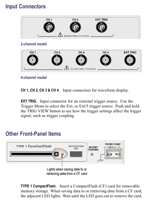
Isolation channel: All channels and Ext Trig inputs are isolated from chassis, supporting independent floating ground measurement with an input impedance of 3M Ω, solving the common ground limitation of traditional oscilloscopes;
Portable power supply: compatible with TPSBAT lithium batteries (standard 1, optional 2), can be charged simultaneously when powered by mains electricity;
Full function analysis: supports peak detection (capturing ≥ 10ns glitches), video triggering (NTSC/PAL/SECAM), FFT spectrum analysis (2048 point transform);
Data interface: Front mounted Type 1 CompactFlash card slot, rear mounted RS-232 (9-pin) and Centronics (parallel printing) interfaces.
Safety operation standards
1. Electrical safety
Voltage limitation: The maximum voltage of the input channel is 300V RMS CAT II. When it exceeds 100kHz, it will attenuate by 20dB/tenfold to avoid arc damage;
Probe safety: The reference end of the P2220 probe is prohibited from floating above 30V RMS. For high voltage measurements, P5120 (600V RMS CAT II) or differential probes are required;
Grounding requirements: A 3-pin power cord must be used and disconnection of the grounding is prohibited; The equipment chassis needs to be reliably grounded to avoid electric shock caused by floating operations.
2. Operation taboos
Prohibit use in damp/explosive environments and avoid liquid spraying equipment;
Before connecting/disconnecting the probe, the signal source must be disconnected first, and live operation is prohibited;
Before disassembling the battery, it is necessary to turn off the device and avoid short circuiting the battery contacts or putting them into a fire.
Basic operation process
1. Probe operation
Key requirements for operation type steps
Manual compensation: 1. Connect the probe to CH1 and set it to 10X; 2. Connect it to PROBE COMP; 3. Autoset; 4. Adjust the compensation hole to a square wave that is flat and free of dents/bulges. Re compensate each time the channel is changed
Attenuation setting 1. Press CHx MENU → Probe → Voltage Attenuation; 2. Choose 1X/10X P2220 and set the bandwidth limit to 6MHz for 1X
Current probe scaling 1. Press CHx MENU → Probe → Current → Scale; 2. Choose a matching value (such as 10A/V) to ensure consistency with the output ratio of the current probe and avoid reading deviation
2. Self calibration and firmware updates
Self calibration:
Disconnect all probes and press 【 Utility 】 → 【 Do Self Cal 】;
Wait for 2 minutes, and upon completion, display 'Calibration PASSED';
Trigger condition: If the environmental temperature difference exceeds 5 ℃ or once a week, preheating for 20 minutes is required.
Firmware update:
Download the latest firmware from the official website and copy it to the root directory of CompactFlash;
Insert the oscilloscope and press 【 Utility 】 → 【 File Utilities 】 → 【 Update Firmware 】;
Wait for completion, do not power off or unplug the card.
Core Systems and Functions
1. Collection system (three modes)
The working principle of the collection mode is applicable to different scenarios
Sampling mode equidistant sampling, 1-point/interval conventional stable signal (sine wave/square wave)
Peak detection mode records the maximum/minimum values of each interval, including signals with spikes and narrow pulses (≥ 10ns)
After multiple acquisitions in average mode, the signal containing random noise (power ripple, sensor output) is averaged (4/16/64/128 times)
2. Trigger system (three types)
Trigger type key parameters applicable scenarios
Edge triggered slope (rising/falling), coupling (AC/DC/noise suppression), stable display of conventional signals (such as clock signals)
Video trigger standards (NTSC/PAL/SECAM), synchronous (field/line) composite video signals (such as medical equipment video output)
Pulse width triggering condition (=≠<>), width (33ns-10s), polarity capture abnormal pulse (such as communication link narrow pulse interference)
3. FFT spectrum analysis
Setting steps:
Center the time-domain signal (align the 0V line with the center of the screen) to ensure complete waveform;
Press Math Menu → Operation → FFT to select the source channel;
Window selection function (Hanning window: excellent frequency resolution; flat top window: excellent amplitude accuracy).
De aliasing method:
Increase sampling rate (switch from SEC/DIV to faster gear);
Enable 20MHz bandwidth limit;
External filtering (adding a low-pass filter at the signal source end).
Battery Management (Core Features)
1. Charging and battery life
Charging method: single battery charging time, dual battery charging sequence, battery life (4-channel model)
In machine (power on), charge the high battery first for 7 hours, then charge the low battery for 4.5 hours (single battery), and 9 hours (dual battery)
In machine (standby) 4.5 hours as above-
External TPSCHG charger can charge 2 units simultaneously in 3 hours-
2. Calibration and maintenance
Calibration:
External calibration: TPSCHG charger left slot → press "Recalibrate", takes about 10 hours (charge discharge cycle);
In machine calibration: discharge to shutdown → charge for 5 hours → discharge to shutdown → recharge for another 5 hours.
Storage:
Temperature: 5-20 ℃, humidity ≤ 80%;
Electricity consumption: about 50%, replenished once every 6 months;
Taboo: Long term full charge (>80%) or empty charge (<20%) storage is prohibited.
Data Storage and Communication
1. CompactFlash card operation
Storage Content File Name Format 1MB Capacity Approximately Storage Quantity Key Operations
18 waveform files FnnnnCHx.CSV, press 【 Save/Recall 】 → 【 Save Waveform 】 → Select Channel
Set file FnnnnTEK.SET to 250, press 【 Save/Recall 】 → 【 Save Setup 】 → select storage location
16 image files FnnnnTEK.BMP, press [Print] (set to "Save Image to File")
2. RS-232 communication settings
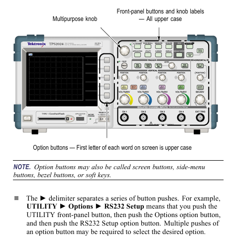
Parameter configuration: Press 【 Utility 】 → 【 Options 】 → 【 RS232 Setup 】 to set the baud rate (default 9600), flow control (Hardtagging), and checksum (None);
Test steps:
Connect the oscilloscope to the PC using cable 012-1379-00;
Open HyperTerminal on the PC and set the same parameters;
Send 'ID?', the oscilloscope returns' ID TEK/TPS2024, CF: 91.1CT, FV: V10.00 '.
Typical application cases
1. Isolation channel measurement differential signal
Connect the probe tip to the positive terminal of the differential signal and the reference terminal to the negative terminal (no common ground required);
Press' AutoSet 'to display the differential waveform;
Press' Single Seq 'to capture a snapshot, and use the cursor to measure the amplitude/rise time.
2. Video signal triggering (NTSC)
Connect the probe to video output, press 【 CH1 MENU 】 → 【 Coupling 】 → 【 AC 】;
Press 【 Trig Menu 】→【 Type 】→【 Video 】→【 Standard 】→【 NTSC 】;
Select [Sync] → [All Lines], adjust SEC/DIV to 500ns/div, and observe the color synchronization signal.
3. Power waveform measurement (voltage x current)
CH1 connected to voltage probe (10X), CH2 connected to current probe (10A/V);
Press 【 Math Menu 】→【 Operation 】→【 × 】→【 CH1 × CH2 】;
Adjust the Math waveform position/scale to display instantaneous power (in VA).
Appendix and Support
1. Key performance parameters
System parameter description
Vertical system resolution 8-bit, 2mV-5V/div
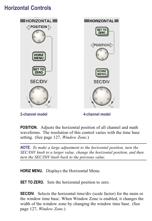
Horizontal system time base range TPS2024:2.5ns-50s/div; TPS2012/2014:5ns-50s/div
Trigger system edge trigger sensitivity DC coupling: 1div (DC-10MHz), 2div (100-200MHz)
Display system resolution of 320 × 240 pixels, 5.7-inch LCD
2. Probe compatibility
Probe model, attenuation ratio, bandwidth, maximum voltage, applicable scenarios
P2220 (Standard) 1X/10X 6MHz/200MHz 150V/300V RMS CAT II Conventional Voltage Measurement
P5120 (optional) 20X 200MHz 1000V RMS CAT II high voltage measurement
TCP303 (optional) 5/50mV/A 15MHz 150A RMS high current AC/DC measurement
- OMRON
- ABB
- General Electric
- EMERSON
- Honeywell
- HIMA
- ALSTOM
- Rolls-Royce
- MOTOROLA
- Rockwell
- Siemens
- Woodward
- YOKOGAWA
- FOXBORO
- KOLLMORGEN
- MOOG
- KB
- YAMAHA
- BENDER
- TEKTRONIX
- Westinghouse
- AMAT
- AB
- XYCOM
- Yaskawa
- B&R
- Schneider
- KONGSBERG
- NI
- WATLOW
- ProSoft
- SEW
- ADVANCED
- Reliance
- TRICONEX
- METSO
- MAN
- Advantest
- STUDER
- DANAHER MOTION
- Bently
- Galil
- EATON
- MOLEX
- DEIF
- B&W
- ZYGO
- Aerotech
- DANFOSS
- Beijer
- Moxa
- Rexroth
- Johnson
- WAGO
- TOSHIBA
- BMCM
- SMC
- HITACHI
- HIRSCHMANN
- Application field
- XP POWER
- CTI
- TRICON
- STOBER
- Thinklogical
- Horner Automation
- Meggitt
- Fanuc
- Baldor
- SHINKAWA
- Other Brands
- UniOP
- KUKA
- Iba
- Beckhoff
- ADLINK
-
 Basler BE1-CDS Current Differential System
 -
 Basler Electric CBS 212 Current Boost System 9 2650 00 100
 -
 Basler Electric IFM-150 Firing Circuit Chassis
 -
 Basler Electric BE1-60 Voltage Balance Relay C1F A1P D0C3F
 -
 Basler Electric BE1-32R Power Relay A2E D1R A0N0F
 -
Basler Electric BE1-32R Power Relay A2E D1R A0N0F
-
 Basler Electric 8650C80G01 Isolation Transducer PCB Board
 -
 ETEL EA-P2M-300-4/7.5A-0100-01 AccurET Modular 300 Servo Drive
 -
 Basler Electric 87T Transformer Differential Relay
 -
 Basler Electric BE-6868 Power Transformer 5950007559202
 -
 Basler Electric PRS250 Veri-Sync Relay 9088800102
 -
 Basler Electric SCP-250-G-60 VAR Power Factor Controller
 -
 Basler DECS-150 AVR 1NS2V1N1S Voltage Regulator
 -
 Basler UFOV 260A Under Frequency Overvoltage Module
 -
 Basler MOC2 199 Motor Operated Control – Overview and Setup
 -
 Basler BE3-49R-5K5A1 Temperature Relay – Complete Guide
 -
Basler BE 20035 001 Transformer – Technical Data and Installation
-
 Basler BE 02727 001 Transformer – Specifications and Usage
 -
 Basler BE127 Under Voltage Relay – Features and Application Guide
 -
 Basler CBS377 Current Boost System – Complete Technical Guide
 -
 Basler BE1-87G P/N 9170818100 Differential Relay – In-Depth Specs
 -
Basler BE1-87G Generator Differential Relay – Technical Overview
-
 Basler Electric SR4A2B16 SVR Static Voltage Regulator – Complete Guide
 -
 Basler Electric 9261500101 Power Supply Module
 -
 Basler Electric AEM-2020 Analog Expansion Module
 -
Basler Electric DGC-2020 Digital Genset Controller 51BRBNEAH001
-
 Basler Electric BE1-59N Ground Fault Overvoltage Relay
 -
 Basler Electric BE1-59N-A5E-E1L-N0S1F Neutral Overvoltage Relay
 -
Basler Electric MOC2499 Motor Operator Control Potentiometer 9072300430
-
 Basler Electric BE1-50/51M Overcurrent Relay
 -
 Basler Electric 9148100106 MOC3502 Solid State Relay 250VDC 0.25A
 -
 Basler Electric CBS 212 Current Boost System 9265000100
 -
 Basler Electric 10493002 Control Module
 -
Basler BE1-32R D3E E1R A0N1F Power Relay
-
 Basler SR8A2B15B3A Static Voltage Regulator
 -
 Basler IFM-105 Firing Circuit Chassis 9324100105
 -
 Basler SR4A2B05B3A Static Voltage Regulator
 -
 Basler BE151G1EB6PB0N0F Protective Relay
 -
Basler BE1-59 Electric Over Voltage Relay
-
 Basler 277 Static Programmable Powerline Carrier Channel
 -
 Basler BE1-32R D1E A1P A0N1F Power Relay
 -
Basler SR4A1B07B3A Static Voltage Regulator
-
 Basler Electric BE1-700 Digital Protective Relay
 -
Basler Electric SR8A-2B01B3A Static Voltage Regulator
-
 Basler Electric SR4A-2B01B3E Static Voltage Regulator
 -
 Basler Electric 9017709102 PC Board
 -
Basler Electric SR4A-2B01B3A Static Voltage Regulator
-
 Basler Electric PRS-250 Veri-Sync Relay
 -
 Basler Electric 9066800102 Excitation Support System
 -
Basler Electric BE1-87G Generator Differential Relay 9 1708 18 100
-
 Basler Electric 36T865-2 BE03752001 Power Supply
 -
 Basler Electric M-300 149D940G02 Power Supply
 -
 Basler Electric ACA2040-25GM 4Mp 25Fps Area Scan Camera
 -
 Basler BE1-87G-S1A-A1C-A0N0 Differential Relay
 -
Basler SR8A-2B06B3E Static Regulator SR8A2B06B3E
-
 Basler SCP-210 Frequency Controller 9095400100
 -
 Basler BE1-59-A3E-A1J-N1N3F Overvoltage Relay BE159A3EA1JN1N3F
 -
Basler 9 2011 11 100 Bracket Mounted Terminal Unit
-
Basler 9 1606 00 101 Voltage Regulator
-
 Basler CBS-377 Current Boost System 9109600102
 -
 Basler 8650C72 Exciter Control Module PCB Rev 5
 -
 Basler C2EE1PA0N1F BE1-32R Reverse Power Relay
 -
 ADLINK HPCI-14S12U - Industrial Control Backplane 12PCI Backplane PCI-14S Passive Backplane
 -
-0010.png) ADLINK PCIe-GIE74C - image acquisition card 4-CH GigE Vision PoE+ Frame Grabber
ADLINK PCIe-GIE74C - image acquisition card 4-CH GigE Vision PoE+ Frame Grabber -
-0010_1.png) ADLINK PCI-8164 - control card 4-Axis Advanced Motion Controller Board
ADLINK PCI-8164 - control card 4-Axis Advanced Motion Controller Board -
 ADLINK PCIe-U304 - 4 Port USB3 PCIe Frame Grabbers USB Screw Hole Card
 -
 ADLINK PCI-9112 - Multi-Function Data Acquisition Card DAQ Card
 -
 ADLINK PCI-7432 - 51-12013-0A50 4-CH Isolated Numérique I/O PCI Cartes Digital I/O Card
 -
 ADLINK PCA-6106P3-0C1 REV.C1 - backplane 6-Slot Passive Backplane Board
 -
 ADLINK PCI-7224 - 24-CH Opto-Isolated Digital I/O PCI Board
 -
 ADLINK CPCI-7433R(G) - Digital Input Board Rear I/O CompactPCI Card
 -
 ADLINK EBP-13E4 - 51-46703-0A30 Industrial PC Backplane Passive Backplane
 -
 ADLINK PCIE-HDV62 - Image acquisition card High Definition Video Frame Grabber
 -
 ADLINK EBP-13E4 - 51-46703-0A30 Industrial Backplane Board Passive Backplane
 -
 ADLINK 90111-B1 / CPCI-6770 - PCB CPU MODULE CompactPCI Single Board Computer
 -
 ADLINK PCI-7248 - DATA ACQUISITION PCI CARD 48-CH Parallel Digital I/O Board
 -
 ADLINK PCI-7230 - 51-12003-0a50 board PCI7230 32-CH Isolated Digital I/O Card
 -
 ADLINK PCI2A000CB - 51-20000-0B30 Multi-Function DAQ Card Baseboard
 -
 ADLINK PCI-8134-005 - 4-Axis Motion Controller Card
 -
 ADLINK PCI-7224 - 24-CH Opto-Isolated Digital I/O PCI Card
 -
 ADLINK PCI-7434 - 64-CH Isolated Digital Output Card
 -
 ADLINK PCI-8132 - motion control card 2-Axis Servo & Stepper Controller
 -
 ADLINK PCI-8134 - Motion Controller PCI Card 4-Axis Controller Board
 -
 ADLINK PCI-8164 - Motion Control Card 51-12406-0A40 4-Axis Controller
 -
 ADLINK 51-12001-0C20 - Circuit Board Data Acquisition Interface Module Hardware
 -
 ADLINK NuPR0-840 - industrial control motherboard Full-Size PICMG CPU Board
 -
 ADLINK PCI-7444 - 51-12023-0A10 card 128-CH Isolated Digital Output Board
 -
 ADLINK PCI-1612B - data acquisition card 4-Port RS-232/422/485 Serial Communication Card
 -
 ADLINK PCI-6208V 009 - 8/16-CH 16-Bit Analog Output Cards PCB-I-E-482=6BX3
 -
 ADLINK NUPRO-935A/LV - industrial control motherboard Full-Size PICMG SBC Board
 -
 ADLINK PCI-9114DG - Multi-Function DAQ Card Data Acquisition PCI Card
 -
 ADLINK ACL-7130 - Data acquisition card Isolated Digital I/O Board
 -
 ADLINK ABX-6300D-4E1-BP - board ABX6300D4E1BP Video Interface Expansion Card
 -
 ADLINK CPCI-6940 - CPCI-6940/D1539/M16-0(EA)-000E 6U CompactPCI Processor Board
 -
 ADLINK NuPRO-760 - industrial control motherboard Half-Size PICMG SBC CPU Board
 -
 ADLINK IMB-M42H (G)-0020 - industrial control motherboard LGA1155 Micro-ATX Mainboard
 -
 ADLINK RTV-24 / PCI-MP4S - 51-12519-1C30 4-Channel Real Time Video Capture Board
 -
 ADLINK PCI-8134 - 4-Axis Servo & Stepper Motion Controller Card
 -
 ADLINK MXC-6101D - V.PC000.002.ST.00 Box PC Configurable Embedded Computer
 -
.png) ADLINK PCI-8134A - 51-12421-0A10 Motion Control Card 4-Axis Controller Card
ADLINK PCI-8134A - 51-12421-0A10 Motion Control Card 4-Axis Controller Card -
 ADLINK DIN-100S / DIN-100SA1 - Technology SCSI-II TB 100-PIN Terminal Block Board
 -
.png) ADLINK DIN-812M001 / DIN812M001 - 51-14034-0A1 51140340A1 Terminal Module Breakout Interface
ADLINK DIN-812M001 / DIN812M001 - 51-14034-0A1 51140340A1 Terminal Module Breakout Interface -
_1.png) ADLINK PCI-8164 - Servo motion control 4-Axis Advanced Controller Card
ADLINK PCI-8164 - Servo motion control 4-Axis Advanced Controller Card -
 ADLINK PCIe-GIE64 - Acquisition card GigE Vision PoE+ Frame Grabber
 -
 ADLINK M-302 - Industrial control motherboard ATX PC Board Mainboard
 -
 ADLINK PCI-8134 - Motion Controller PCI Card 4-Axis Controller Board
 -
 ADLINK PCI-RTV24 - Image capture card Analog Video Frame Grabber
 -
 ADLINK PCI-8102 - Motion control card 2-Axis Servo & Stepper Controller Board
 -
 ADLINK PCI-9112 REV.B1 - Card Multi-Function Data Acquisition Card
 -
 ADLINK HSI-DI32-M-N / HSL-TB32-M-DIN - Discrete I/O MODULE Distributed Automation Module System
 -
 ADLINK PCI-7296 - IO card REV.A3 96-CH Parallel Digital I/O Card
 -
-0020.png) ADLINK DIN-814P-A4 / 814Y - terminal board Motion Control Interface Block
ADLINK DIN-814P-A4 / 814Y - terminal board Motion Control Interface Block -
 ADLINK DIN-814P-A4 - 51-14056-0A10 PCB-I-E-2736=ZA01 Screw Terminal Board Breakout
 -
 ADLINK M-322 - motherboard Industrial Control Computer Mainboard
 -
 ADLINK NUPRO-406 REV:B1 - industrial control motherboard Full-Size PICMG CPU Board
 -
 ADLINK AMP-204C - card DSP-Based 4-Axis Advanced Pulse-Train Controller
 -
 ADLINK HPCI14S REV.B1 - industrial computer baseboard 14-Slot Passive Backplane
 -
 ADLINK PCI-7250 - 8-CH Relay Output & 8-CH Isolated DI PCI Card
 -
 ADLINK EBP-13E2 - baseplate Passive Backplane Industrial Computer Chassis Board
 -
 ADLINK LPCI-3488A - PCI-GPIB card 51-12801-0A30 acquisition card IEEE-488 Interface Board
 -
 ADLINK PCI-6216V-GL - 51-12201-0C30 16-CH 16-Bit Voltage Analog Output Card
 -
 ADLINK ACL-8454 - 16-CH Isolated Digital I/O & 4-CH Counter Card
 -
 ADLINK HPCI-9S7U - backplane Passive Backplane Compatible with NuPRO-A301 852 841 842
 -
 ADLINK DAQ-2010-007 - Simultaneous-Sampling Multi-Function Data Acquisition Card
 -
 ADLINK MP-C154 - 51-64205-0A10 Motion Control Card 4-Axis Controller Board
 -
 ADLINK MXE-202/mSSD16B/WiFi-BT - Matrix Rugged I/O Platform Embedded Fanless Computer
 -
 ADLINK CM-920-R-17 - PC/104-Plus Single Board Computer Module Intel Celeron M
 -
 ADLINK PCI-7250 NSMP - 8-CH Relay Output & 8-CH Isolated DI Card


