
YASKAWA AC Drive V1000 Compact Vector Control Drive
Core purpose: To guide users in correctly installing, operating, and debugging frequency converters, ensuring safe and stable operation of the equipment.
Copyright and Revision: First published in 2007, latest revised in December 2016, including updates to safety standards, functional supplements, and more.
YASKAWA AC Drive V1000 Compact Vector Control Drive
Basic information of the document
Applicable models: 200V level (single-phase input 0.1-4.0kW, three-phase input 0.1-18.5kW), 400V level (three-phase input 0.37-18.5kW) CIMR-V series frequency converters.
Core purpose: To guide users in correctly installing, operating, and debugging frequency converters, ensuring safe and stable operation of the equipment.
Copyright and Revision: First published in 2007, latest revised in December 2016, including updates to safety standards, functional supplements, and more.
Key content of core chapters
1. Safety instructions and warnings
Risk classification: Clearly define three types of warnings: Warning (fatal/serious injury), CAUTION (minor/moderate injury), and NOTICE (equipment damage).
Core taboos: Do not modify equipment, touch terminals before discharge, and operate by non professionals; Strict adherence to grounding regulations is required (leakage current exceeding 3.5mA, grounding conductor cross-section ≥ 10mm ² (copper)/16mm ² (aluminum)).
Special risk: During the rotation self-tuning period, the motor may suddenly start, and after power failure, it is necessary to wait for the capacitor to fully discharge (at least 5 minutes).
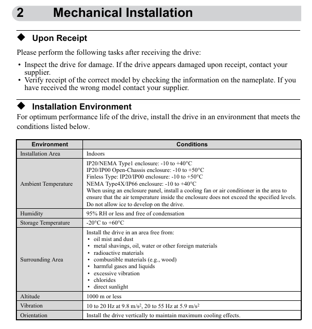
2. Mechanical installation
Environmental requirements: Indoor installation, temperature -10~+50 ℃ (adjusted according to protection level), humidity ≤ 95%, no condensation, no dust, oil pollution, vibration and other interference.
Installation specifications: Vertical installation is required to ensure heat dissipation, and 30mm (on both sides) and 100mm (up and down) heat dissipation space should be reserved around the equipment.
Acceptance and verification: After receiving the goods, check that the equipment is not damaged and verify the nameplate to confirm that the model is correct.
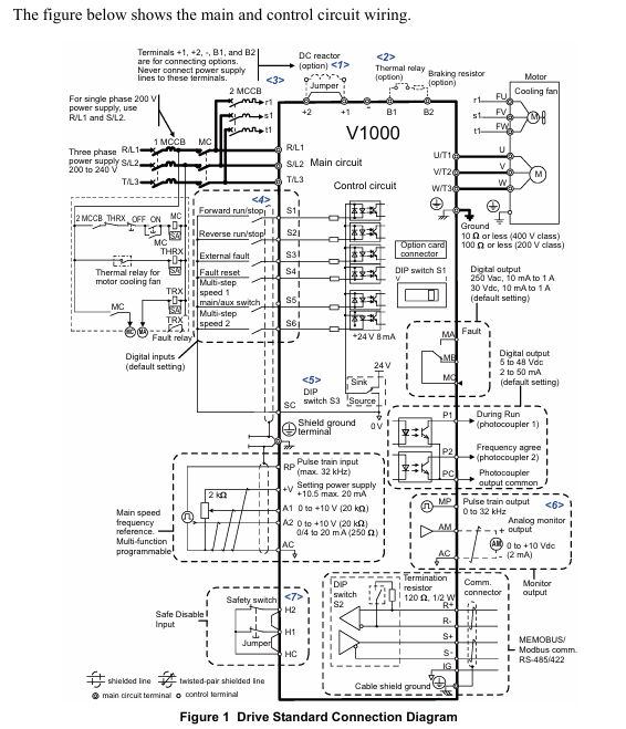
3. Electrical installation
Wiring specifications: The main circuit power supply is connected to R/L1, S/L2, T/L3 (only R/L1, S/L2 are used for single-phase), the motor is connected to U/T1, V/T2, W/T3, and it is forbidden to connect the power supply to the output terminal.
Cable requirements: The control circuit should use shielded twisted pair cables to avoid mixing with the main circuit cables; The specifications of the main circuit cables need to match the model (such as 2.5mm ², 6mm ², etc.).
EMC compliance: A designated EMC filter must be installed on the input side, and the grounding surface must be repainted to ensure low impedance.
4. Keyboard operation and startup debugging
Keyboard functions: including RUN/STOP start and stop keys, parameter setting keys, mode switching keys (LOCAL/REMOTE), LED indicator lights to display running status, faults, and other information.
Start up process: Install wiring → Power on → Select control mode (V/f, open-loop vector, etc.) → Set load type (standard/heavy load) → Motor self-tuning (or manually input motor parameters) → I/O configuration → Trial operation → Load operation.
Mode selection: V/f control is suitable for multi motor drive, open-loop vector control is suitable for high-precision speed regulation, and open-loop vector control of permanent magnet motor focuses on energy saving.
5. Key parameters and troubleshooting
Core parameters: including frequency reference (b1-01), acceleration and deceleration time (C1-01/C1-02), motor rated current (E2-01), overload protection (L1-01), etc.
Troubleshooting: List common faults (such as overcurrent, overvoltage, overload) and their corresponding causes and solutions, including troubleshooting methods for programming errors (oPE series) and self-tuning errors (Er series).
Safety disable function: Compliant with SIL2/PL safety standards, controlled through HC and H1 terminals, the motor torque is cut off within 1ms when disconnected, requiring professional personnel to wire and debug.
6. UL/cUL compliance requirements
Installation restrictions: Pollution level ≤ 2, ambient temperature -10~+50 ℃ (depending on protection level).
Wiring specification: Use UL certified copper wire, and the terminal tightening torque must comply with the standard (such as 0.8-1.0N · m for M3.5 terminals).
Protection configuration: The input side needs to be equipped with a specified type of fuse (such as Class J/T/CC), and the motor overload protection is set through parameters E2-01 and L1-01.
Precautions for use
Operators must possess professional qualifications and strictly adhere to the safety regulations outlined in the manual.
The equipment needs regular inspection and maintenance, with daily safety function checks. It is recommended to replace it after 10 years of use.
When the safety disable function is not used, the HC and H1 terminals must be kept short circuited; Modifying the equipment will result in the expiration of the warranty.
- OMRON
- ABB
- General Electric
- EMERSON
- Honeywell
- HIMA
- ALSTOM
- Rolls-Royce
- MOTOROLA
- Rockwell
- Siemens
- Woodward
- YOKOGAWA
- FOXBORO
- KOLLMORGEN
- MOOG
- KB
- YAMAHA
- BENDER
- TEKTRONIX
- Westinghouse
- AMAT
- AB
- XYCOM
- Yaskawa
- B&R
- Schneider
- KONGSBERG
- NI
- WATLOW
- ProSoft
- SEW
- ADVANCED
- Reliance
- TRICONEX
- METSO
- MAN
- Advantest
- STUDER
- DANAHER MOTION
- Bently
- Galil
- EATON
- MOLEX
- DEIF
- B&W
- ZYGO
- Aerotech
- DANFOSS
- Beijer
- Moxa
- Rexroth
- Johnson
- WAGO
- TOSHIBA
- BMCM
- SMC
- HITACHI
- HIRSCHMANN
- Application field
- XP POWER
- CTI
- TRICON
- STOBER
- Thinklogical
- Horner Automation
- Meggitt
- Fanuc
- Baldor
- SHINKAWA
- Other Brands
- UniOP
- KUKA
- Iba
- Beckhoff
-
 Basler D90 96801 100 PCB Card
 -
 Basler XR2002F Voltage Regulator (110 VAC, 48-480 Hz)
 -
 Basler SR8A-2B14B3A Regulator
 -
 Basler 9561500100 Module
 -
 Basler DECS-400 BE1-11 System
 -
 Basler DECS-100-B15 Excitation Control
 -
 Basler SCP 210 Frequency Controller
 -
 Basler SR4A-2B15B3A Static Voltage Regulator
 -
 Basler BE1-32R Power Relay
 -
 Basler PIA2400-17GM Power Interface Adapter
 -
 Basler MVC 232 Manual Voltage Control Module
 -
 Basler SSR 32-12 Static Voltage Regulator
 -
 Basler 5MW AVR Generator Voltage Regulator
 -
 Basler VR63-4B Voltage Regulator
 -
 Basler DECS-100-A05 AVR for Engine Generator
 -
 Basler DECS-100-B15 Automatic Voltage Regulator
 -
 Basler BE1-32R Directional Power Relay
 -
 Basler BE1-87B Differential Relay
 -
 Basler UFOV 260A Protective Module
 -
 Basler 9-2614-02-100 PCB Rev M
 -
Basler DECS-100-B15 Digital AVR
-
 Basler 9284900103 PS DECS-400N
 -
 Basler D4N3H1U Intertie Protection
 -
 Basler DECS-100-B15 A15 AVR
 -
 Basler KR4F Voltage Regulator
 -
 Basler BE26434 T14 Transformer
 -
 Basler SR8A-2B15B3A Regulator
 -
 Westinghouse 774B472A12 AR Relay
 -
Basler DECS-100-B15 AVR
-
Basler XR2002F Regulator 110V
-
Basler SR125-E Static Regulator
-
 Basler SSR 125-12 Regulator
 -
 Basler MOC2599 Motor Pot
 -
 Basler BE1-DFPR Feeder Relay
 -
 Basler CBS 305 Current Boost
 -
 Basler BE1-25 AutoSync
 -
 Basler MVC 300 Voltage Control
 -
 Basler BE3-25A AutoSync
 -
 Basler KR7FF Static Regulator
 -
 Basler 90-49000-100 Regulator
 -
 Basler 880 kVA Dry Type Transformer Specs
 -
 Basler Electric BE1-25 Sync-Check Relay Specs
 -
 Basler SSR 125-12 Voltage Regulator Specs
 -
 Basler Electric BE1-851 Overcurrent Relay Review
 -
Basler Electric 149D930G02 Control Sub-Assembly
-
 Basler Electric BE1-81O/UT Frequency Relay Specs
 -
 Basler Electric BE1-51/27C Overcurrent Relay
 -
 Basler Electric 149D956G02 Industrial Component
 -
Basler Electric BE1-51A Overcurrent Relay Specs
-
 Basler Electric BE1-40Q Loss of Excitation Relay
 -
 Basler DECS-200 Excitation Control System
 -
 Basler DECS-200 Voltage Regulator 56-277V AC / 125V DC
 -
Basler BE1-87T Transformer Differential Relay
-
 Basler RDP-110-S1 Protection Relay
 -
 Basler BE1-700V Digital Protective Relay
 -
 Basler BE1-951 Overcurrent Protection System
 -
 Basler DECS-300 Digital Excitation Control
 -
 Basler DECS-200 Digital Excitation Control
 -
 Basler DECS-200-1C Excitation Control System
 -
Basler DECS-200-1L Digital Excitation Control
-
 Basler Electric BE1-GPS Generator Protection System
 -
Basler Electric DECS-200-1C Digital Excitation Controller
-
 Basler Electric DECS125-15 Excitation Control with Power Module
 -
 Basler Electric BE1-87G Differential Relay
 -
 Basler Electric BE1-11 Protection System I5A3M2P2N0EA00
 -
Basler Electric DECS-200-1C Excitation Control System
-
Basler Electric BE1-11g Generator Protection Relay
-
Basler Electric DECS 125-15-B2C1 V2.0.9 Excitation Control
-
 Basler Electric BE1-81O/UT3ED1JA7N2F Frequency Relay
 -
Basler Electric BE1-81O/UT3EE1YB7N1F Frequency Relay
-
 Basler Electric DECS-200-1L Digital Excitation Control System
 -
Basler DECS125-15-B2C1 Excitation Control
-
 Basler 9507900205 SSR Retrofit Voltage Regulator
 -
 Basler BE2000E Digital Voltage Regulator
 -
 Basler BE1-GPS Generator Protection System
 -
Basler DECS-250-CN1CN1N Digital Excitation Control
-
 Basler DGC-2020 Genset Controller
 -
 Basler BE1-81O UT3ED1LA7N0F Frequency Relay (Variant)
 -
 Basler BE1-81O UT3EE1YA9S0F Frequency Relay (Variant)
 -
Basler BE1-81O Over/Under Frequency Relay
-
Basler DECS125-15 Digital Excitation Control
-
Basler Electric BE1-951 Overcurrent Protection System
-
 Basler Electric BE1-700V Digital Protective Relay
 -
 Basler Electric APR63-5 Automatic Voltage Regulator
 -
Basler Electric BE1-851 Overcurrent Protection System
-
Basler Electric DECS-250-LN1SN1N Excitation Control
-
 Basler Electric BE1-87T Transformer Differential Relay
 -
Basler Electric DECS-200-1L Excitation Control System
-
 Basler Electric 9310300100 DECS-300 Excitation Control
 -
 Basler Electric SSE-N 125-4.5KW Shunt Exciter Regulator
 -
 Basler Electric DGC-2020HD-5NS1DNSBA Genset Controller
 -
Basler Electric BE1-81-O/UT3EE1JB7N1F Frequency Relay
-
Basler Electric BE1-81T1EE1WA0N1F Frequency Relay
-
 Basler Electric BE1-25M1EA6PN5R1F Sync-Check Relay
 -
 Basler Electric BE1-GPS Generator Protection System
 -
Basler Electric DECS-250-LN1SN1N Excitation Control Rev V
-
 Basler Electric DECS-250-CN2CN1N Excitation Control
 -
Basler Electric BE1-50/51B-207 Overcurrent Relay
-
Basler Electric DECS-300-C0N0 Excitation Control System
-
Basler Electric DECS-200 Digital Excitation Control System
-
Basler Electric DECS-250-LN1CN1N Excitation Unit
-
Basler Electric DECS-250 LN2SA1D Excitation Unit Specs
-
Basler Electric BE1-87T Transformer Relay Review
-
Basler Electric BE1-11 Protection System
-
Basler Electric BE1-GPS100-E4N1H1N Protection System
-
 Allen-Bradley 442G-MABH-R Safety Module
 -
 Beckhoff CX1030-0111 PLC Assembly Profile
 -
 FANUC IC693CPU364 PLC Module
 -
 Orange Denmark Type 200816 220 PLC Specs
 -
 OMRON C200H-SNT31 Sysmac PLC Module
 -
 Allen Bradley 20AB022A3AYNANC0 PowerFlex 70
 -
 OMRON C200HW-PCU01 Position Control Unit
 -
 ABB AO845A-eA Analog Output Module
 -
 OMRON CJ1M-CPU22 CPU Unit
 -
 Allen Bradley 100-E265ED11 Contactor
 -
 Honeywell 51304511-100 Interface Module
 -
 SOLEXY BXF3S0101N0018 Gateway Module
 -
 OMRON CJ2H-CPU65 CPU Unit
 -
 Automation Direct GS2-45P0 AC Drive
 -
 M68-2000 2-Axis Motion CNC Controller
 -
 OMRON CJ1M-CPU11 V3.0 PLC CPU Unit
 -
 OMRON CJ1W-NC413 4-Axis Positioning Controller
 -
 OMRON 3G2A3-PRO16 Programming Console HMI
 -
 Siemens 3VT8440-2AA04-2GA2 Molded Case Circuit Breaker
 -
 Siemens 3RT5045 Contactor Series
 -
 OMRON C200HS-CPU01-E SYSMAC PLC Controller
 -
 OMRON C500-NC103-E Positioning Control Unit
 -
 OMRON CJ1W-TC001 Temperature Control Unit


