
YASKAWA VARISPEED-626M/656MR5 series vector control frequency converter
YASKAWA VARISPEED-626M/656MR5 series vector control frequency converter
Document Fundamentals and Product Overview
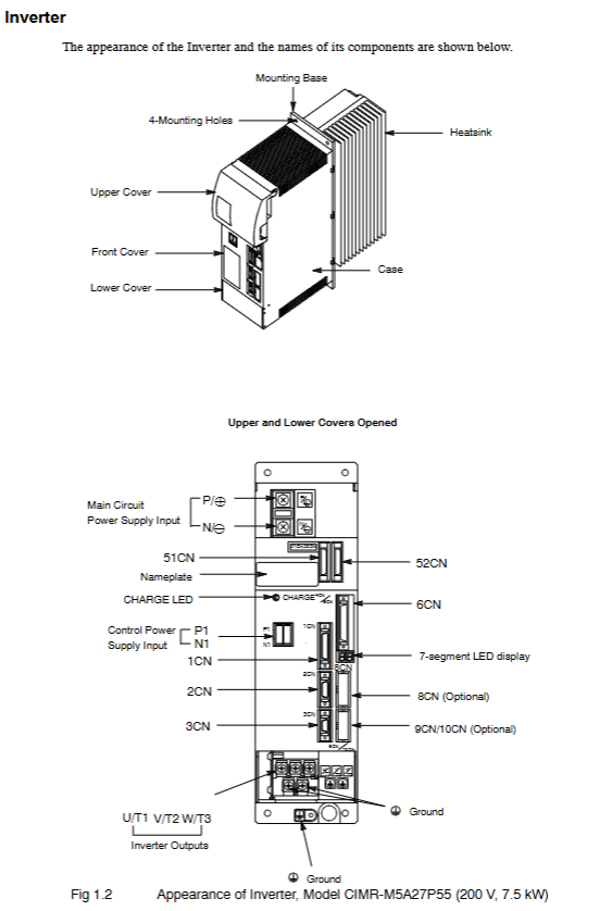
Document positioning: Yaskawa VARISPEED-626M5656MR5 series user manual, mainly used for vector control inverters/converters with power regeneration function for machine tools, guiding installation, maintenance, troubleshooting, and specification inquiry.
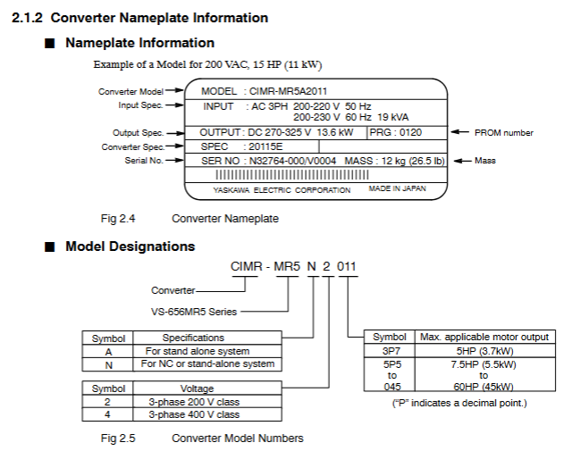
Product model and specifications:
Product Type Model Voltage Level Power Range (kW) Power Range (HP) Remarks
Variable frequency drive (VS-626M5) CIMR-M5 200V level 3.7/2.2-37/30 5/3-50/40 including M5A (independent drive), M5N (NC system)
Variable frequency drive (VS-626M5) CIMR-M5 400V level 5.5/3.7-45/37 7.5/5-60/50 including M5A (independent drive), M5N (NC system)
Converter (VS-656MR5) CIMR-MR5 200V class 3.7/2.2-37/30 5/3-50/40, including MR5A (without 24V control power supply) and MR5N (with 24V control power supply)
Converter (VS-656MR5) CIMR-MR5 400V class 5.5/3.7-45/37 7.5/5-60/50 including MR5A (without 24V control power supply), MR5N (with 24V control power supply)
Warranty information:
Warranty period: 12 months after delivery to the customer or 18 months from the date of shipment from the Yaskawa factory, whichever comes first.
Warranty scope: Only covers faults caused by defects in Yaskawa craftsmanship or materials, excluding improper maintenance, modification, and use beyond specifications.
Regional restrictions: Warranty services are only free within Japan and require payment overseas.
Safety regulations and operating taboos
Definition of Security Level:
Warning: Potential hazardous situation that, if not avoided, may result in death or serious personal injury (such as opening the cover with electricity, not grounded).
CAUTION: Potential hazardous situation that, if not avoided, may result in minor/moderate personal injury or equipment damage (such as grabbing the front cover during transportation or installing on flammable materials).
Core security precautions:
Power off operation: Before wiring or disassembling the digital operator (JVOP-132), the power must be turned off and the capacitor must be discharged (refer to the warning label time, usually 5 minutes).
Grounding requirements: 200V level grounding resistance ≤ 100 Ω, 400V level grounding resistance ≤ 10 Ω. It is strictly prohibited to share the ground with welding machines and high current equipment.
Temperature control: The ambient temperature of the frequency converter/inverter should be ≤ 55 ℃ (131 ° F), and the inlet temperature of the heat sink should be ≤ 45 ℃ (113 ° F). A fan or cooling device should be installed.
Operation taboos:
Do not connect the power supply to the output terminals of the frequency converter (U/T1, V/T2, W/T3), otherwise it will damage the internal components.
Do not connect phase-shifting capacitors, LC/RC noise filters, or electromagnetic switches in the output circuit, as it may cause damage or overcurrent to the frequency converter.
Do not modify the product, otherwise the warranty will expire and may cause electric shock/injury.
Equipment installation and wiring
Delivery Confirmation (CAUTION):
Check if the model is consistent with the order (verify the nameplate), if there is no transportation damage to the appearance, if screws or other components are loose, and if damaged/missing equipment is not allowed to be installed.
Installation requirements:
Environment: Indoor, no corrosive/explosive gases, no dust/metal particles, avoid direct sunlight, vibration acceleration ≤ 2.5G (10-60Hz).
Installation material: It must be installed on non combustible materials such as metal.
Distance requirement (to ensure heat dissipation):
Equipment type, left and right spacing, up and down spacing, note
External heat dissipation type ≥ 120mm ≥ 120mm Side spacing ≥ 5mm
Open chassis type ≥ 150mm ≥ 150mm Side spacing ≥ 5mm
Wiring specifications:
Main circuit wiring: Use the specified wire diameter (such as 200V level frequency converter CIMR-M5A23P7, main circuit wire diameter ≥ 2mm ²), and the terminal screw torque meets the requirements (such as M5 screw 2.35N · m).
Control circuit wiring: Separate the control signal line from the power line, with a length of ≤ 20m, and use shielded twisted pair to avoid wiring in the same conduit.
Core functions and operations
Digital Operator (JVOP-132):
Function: Display operating status (motor speed U1-01, torque reference U1-04), set control constants, fault reset, single machine trial run.
Operation mode: Set from positions 1 to 37, with 11 being the digital operator operation mode, which can achieve jog (5% rated speed) and forward/reverse control.
Trial operation process:
Check the power supply voltage (200V level 3-phase 200-230V, 400V level 3-phase 400-460V).
(NC system) Set YENET1200 node address (rotary switch SW1).
Connect the control power supply and confirm that the frequency converter displays "-" and the inverter displays "- U".
Connect the main circuit power supply, the inverter display changes to "- b", and the CHARGE light is on.
Check the direction of the motor cooling fan (standard intake from the load side).
Send RUN signal to confirm the motor direction (counterclockwise when viewed from the load end during forward rotation) and no abnormal vibration/noise.
Directional control:
Encoder directional control:
Resolution: 360 °/4096=0.088 °, repeatability accuracy ± 0.2 °.
Applicable scenario: The load shaft is connected 1:1 to the motor shaft and requires a load shaft encoder (such as NE-1024-2MDF-068).
Magnetic sensor directional control:
Repetition accuracy ± 0.2 °, using magnet (MG-1378BS) and magnetic sensor (FS-1378C), detection range ± 15mm.
Troubleshooting and Maintenance
Common faults and solutions:
Fault code, fault type, cause, and handling measures
AL-01 inverter overcurrent output short circuit, ground fault check wiring, confirm no short circuit
AL-11 main circuit overvoltage input voltage is too high, load inertia is large. Check the power supply and adjust the acceleration time from C1 to 10
AL-20 winding switching fault switching was not completed within the specified time. Check the contactor wiring and confirm the C1-25 motor code
Maintenance cycle:
Daily inspection: motor abnormal noise, vibration, ambient temperature, display screen values.
Regular inspection:
Remarks on component replacement cycle
Cooling fan has accumulated 20000 hours of operation over 2-3 years
Filter capacitor for 5 years at an ambient temperature of 30 ℃
Motor bearings disassembled and inspected for wear after 12000 hours/2 years
- OMRON
- ABB
- General Electric
- EMERSON
- Honeywell
- HIMA
- ALSTOM
- Rolls-Royce
- MOTOROLA
- Rockwell
- Siemens
- Woodward
- YOKOGAWA
- FOXBORO
- KOLLMORGEN
- MOOG
- KB
- YAMAHA
- BENDER
- TEKTRONIX
- Westinghouse
- AMAT
- AB
- XYCOM
- Yaskawa
- B&R
- Schneider
- KONGSBERG
- NI
- WATLOW
- ProSoft
- SEW
- ADVANCED
- Reliance
- TRICONEX
- METSO
- MAN
- Advantest
- STUDER
- DANAHER MOTION
- Bently
- Galil
- EATON
- MOLEX
- DEIF
- B&W
- ZYGO
- Aerotech
- DANFOSS
- Beijer
- Moxa
- Rexroth
- Johnson
- WAGO
- TOSHIBA
- BMCM
- SMC
- HITACHI
- HIRSCHMANN
- Application field
- XP POWER
- CTI
- TRICON
- STOBER
- Thinklogical
- Horner Automation
- Meggitt
- Fanuc
- Baldor
- SHINKAWA
- Other Brands
- UniOP
- KUKA
- Iba
- Beckhoff
-
 Basler D90 96801 100 PCB Card
 -
 Basler XR2002F Voltage Regulator (110 VAC, 48-480 Hz)
 -
 Basler SR8A-2B14B3A Regulator
 -
 Basler 9561500100 Module
 -
 Basler DECS-400 BE1-11 System
 -
 Basler DECS-100-B15 Excitation Control
 -
 Basler SCP 210 Frequency Controller
 -
 Basler SR4A-2B15B3A Static Voltage Regulator
 -
 Basler BE1-32R Power Relay
 -
 Basler PIA2400-17GM Power Interface Adapter
 -
 Basler MVC 232 Manual Voltage Control Module
 -
 Basler SSR 32-12 Static Voltage Regulator
 -
 Basler 5MW AVR Generator Voltage Regulator
 -
 Basler VR63-4B Voltage Regulator
 -
 Basler DECS-100-A05 AVR for Engine Generator
 -
 Basler DECS-100-B15 Automatic Voltage Regulator
 -
 Basler BE1-32R Directional Power Relay
 -
 Basler BE1-87B Differential Relay
 -
 Basler UFOV 260A Protective Module
 -
 Basler 9-2614-02-100 PCB Rev M
 -
Basler DECS-100-B15 Digital AVR
-
 Basler 9284900103 PS DECS-400N
 -
 Basler D4N3H1U Intertie Protection
 -
 Basler DECS-100-B15 A15 AVR
 -
 Basler KR4F Voltage Regulator
 -
 Basler BE26434 T14 Transformer
 -
 Basler SR8A-2B15B3A Regulator
 -
 Westinghouse 774B472A12 AR Relay
 -
Basler DECS-100-B15 AVR
-
Basler XR2002F Regulator 110V
-
Basler SR125-E Static Regulator
-
 Basler SSR 125-12 Regulator
 -
 Basler MOC2599 Motor Pot
 -
 Basler BE1-DFPR Feeder Relay
 -
 Basler CBS 305 Current Boost
 -
 Basler BE1-25 AutoSync
 -
 Basler MVC 300 Voltage Control
 -
 Basler BE3-25A AutoSync
 -
 Basler KR7FF Static Regulator
 -
 Basler 90-49000-100 Regulator
 -
 Basler 880 kVA Dry Type Transformer Specs
 -
 Basler Electric BE1-25 Sync-Check Relay Specs
 -
 Basler SSR 125-12 Voltage Regulator Specs
 -
 Basler Electric BE1-851 Overcurrent Relay Review
 -
Basler Electric 149D930G02 Control Sub-Assembly
-
 Basler Electric BE1-81O/UT Frequency Relay Specs
 -
 Basler Electric BE1-51/27C Overcurrent Relay
 -
 Basler Electric 149D956G02 Industrial Component
 -
Basler Electric BE1-51A Overcurrent Relay Specs
-
 Basler Electric BE1-40Q Loss of Excitation Relay
 -
 Basler DECS-200 Excitation Control System
 -
 Basler DECS-200 Voltage Regulator 56-277V AC / 125V DC
 -
Basler BE1-87T Transformer Differential Relay
-
 Basler RDP-110-S1 Protection Relay
 -
 Basler BE1-700V Digital Protective Relay
 -
 Basler BE1-951 Overcurrent Protection System
 -
 Basler DECS-300 Digital Excitation Control
 -
 Basler DECS-200 Digital Excitation Control
 -
 Basler DECS-200-1C Excitation Control System
 -
Basler DECS-200-1L Digital Excitation Control
-
 Basler Electric BE1-GPS Generator Protection System
 -
Basler Electric DECS-200-1C Digital Excitation Controller
-
 Basler Electric DECS125-15 Excitation Control with Power Module
 -
 Basler Electric BE1-87G Differential Relay
 -
 Basler Electric BE1-11 Protection System I5A3M2P2N0EA00
 -
Basler Electric DECS-200-1C Excitation Control System
-
Basler Electric BE1-11g Generator Protection Relay
-
Basler Electric DECS 125-15-B2C1 V2.0.9 Excitation Control
-
 Basler Electric BE1-81O/UT3ED1JA7N2F Frequency Relay
 -
Basler Electric BE1-81O/UT3EE1YB7N1F Frequency Relay
-
 Basler Electric DECS-200-1L Digital Excitation Control System
 -
Basler DECS125-15-B2C1 Excitation Control
-
 Basler 9507900205 SSR Retrofit Voltage Regulator
 -
 Basler BE2000E Digital Voltage Regulator
 -
 Basler BE1-GPS Generator Protection System
 -
Basler DECS-250-CN1CN1N Digital Excitation Control
-
 Basler DGC-2020 Genset Controller
 -
 Basler BE1-81O UT3ED1LA7N0F Frequency Relay (Variant)
 -
 Basler BE1-81O UT3EE1YA9S0F Frequency Relay (Variant)
 -
Basler BE1-81O Over/Under Frequency Relay
-
Basler DECS125-15 Digital Excitation Control
-
Basler Electric BE1-951 Overcurrent Protection System
-
 Basler Electric BE1-700V Digital Protective Relay
 -
 Basler Electric APR63-5 Automatic Voltage Regulator
 -
Basler Electric BE1-851 Overcurrent Protection System
-
Basler Electric DECS-250-LN1SN1N Excitation Control
-
 Basler Electric BE1-87T Transformer Differential Relay
 -
Basler Electric DECS-200-1L Excitation Control System
-
 Basler Electric 9310300100 DECS-300 Excitation Control
 -
 Basler Electric SSE-N 125-4.5KW Shunt Exciter Regulator
 -
 Basler Electric DGC-2020HD-5NS1DNSBA Genset Controller
 -
Basler Electric BE1-81-O/UT3EE1JB7N1F Frequency Relay
-
Basler Electric BE1-81T1EE1WA0N1F Frequency Relay
-
 Basler Electric BE1-25M1EA6PN5R1F Sync-Check Relay
 -
 Basler Electric BE1-GPS Generator Protection System
 -
Basler Electric DECS-250-LN1SN1N Excitation Control Rev V
-
 Basler Electric DECS-250-CN2CN1N Excitation Control
 -
Basler Electric BE1-50/51B-207 Overcurrent Relay
-
Basler Electric DECS-300-C0N0 Excitation Control System
-
Basler Electric DECS-200 Digital Excitation Control System
-
Basler Electric DECS-250-LN1CN1N Excitation Unit
-
Basler Electric DECS-250 LN2SA1D Excitation Unit Specs
-
Basler Electric BE1-87T Transformer Relay Review
-
Basler Electric BE1-11 Protection System
-
Basler Electric BE1-GPS100-E4N1H1N Protection System
-
 Allen-Bradley 442G-MABH-R Safety Module
 -
 Beckhoff CX1030-0111 PLC Assembly Profile
 -
 FANUC IC693CPU364 PLC Module
 -
 Orange Denmark Type 200816 220 PLC Specs
 -
 OMRON C200H-SNT31 Sysmac PLC Module
 -
 Allen Bradley 20AB022A3AYNANC0 PowerFlex 70
 -
 OMRON C200HW-PCU01 Position Control Unit
 -
 ABB AO845A-eA Analog Output Module
 -
 OMRON CJ1M-CPU22 CPU Unit
 -
 Allen Bradley 100-E265ED11 Contactor
 -
 Honeywell 51304511-100 Interface Module
 -
 SOLEXY BXF3S0101N0018 Gateway Module
 -
 OMRON CJ2H-CPU65 CPU Unit
 -
 Automation Direct GS2-45P0 AC Drive
 -
 M68-2000 2-Axis Motion CNC Controller
 -
 OMRON CJ1M-CPU11 V3.0 PLC CPU Unit
 -
 OMRON CJ1W-NC413 4-Axis Positioning Controller
 -
 OMRON 3G2A3-PRO16 Programming Console HMI
 -
 Siemens 3VT8440-2AA04-2GA2 Molded Case Circuit Breaker
 -
 Siemens 3RT5045 Contactor Series
 -
 OMRON C200HS-CPU01-E SYSMAC PLC Controller
 -
 OMRON C500-NC103-E Positioning Control Unit
 -
 OMRON CJ1W-TC001 Temperature Control Unit


