YASKAWA AC Servo Drive HR Series (CACR-HR) Multi functional/Positioning Control
YASKAWA AC Servo Drive HR Series (CACR-HR) Multi functional/Positioning Control
Overview
This document is a multifunctional/positioning control manual for the Yaskawa AC servo drive HR series (model CACR-HR, including rack mounted CACR-HR □□ BAB and base mounted CACR-HR □□□ BB), covering in detail the model identification, rated specifications (such as motor output power 0.07-8.2HP, drive input voltage 100-230VAC), mechanical characteristics (allowing radial/axial loads, anti vibration and anti impact performance), wiring connections (typical connections and terminal definitions for main circuit/control circuit/encoder/brake power supply, etc.) of the servo motor (M/F/G/D/S/R/P series) and servo drive I/O signal operation (2CN/5CN input/output signal timing and function), serial communication (RS422 protocol, supporting baud rates such as 9600/4800), parameter setting (100 parameters, including core parameters such as position loop gain Kp and speed loop gain Kv), display/monitoring function (LED indicator light and 7-segment digital tube status display), installation and wiring specifications, trial operation and maintenance (battery replacement, troubleshooting), while emphasizing safety precautions (such as opening the cover after 5 minutes of power outage, anti electric shock/anti scald measures), providing comprehensive guidance for the selection, installation, debugging and maintenance of servo systems.
Product Model and Configuration
1. Analysis of servo motor models (taking USAGED-13A2 as an example)
Explanation of the meaning of model segmentation
USA product prefix Yaskawa servo motor identification
G series (fully enclosed self cooling type, IP65 protection)
ED structural characteristics with encoder
13 output specification 1.3kW (corresponding to 1.7HP)
A-axis end specification with keyway
2 encoder types incremental 8192P/R
2. Analysis of servo drive models (taking CACR-HR03BAB12 as an example)
Explanation of the meaning of model segmentation
CACR-HR Product Series Yaskawa HR Series Servo Drivers
03 Output capacity 300W (0.4HP)
BAB installation and power supply B=rack mounted, A=single-phase, B=200VAC
12th Design Version 12th Design
3. Matching principle between motor and driver
Power matching: The output capacity of the driver needs to cover the rated power of the motor (such as a 300W motor matched with HR03 series driver).
Voltage matching: 100V motor (R series DS model) matches HR □□ BAB11 driver, 200V motor matches HR □□ BAB12/BB driver.
Encoder matching: The absolute encoder motor requires the driver to support battery backup (the HR series panel comes with a 3.6V battery).

Rated specifications and mechanical characteristics
1. Core specifications of servo motors (examples by series)
Motor series model example Rated output Rated speed Rated torque Peak torque Encoder type
M-series USAMED-03B2 0.3kW (0.4HP) 1000r/min 2.84N · m 8.92N · m incremental 8192P/R
S-series USASEM-15A2 1.5kW (2.1HP) 3000r/min 4.90N · m 13.7N · m incremental 2048P/R
R series (200V) USAREM-05CS 500W (0.67HP) 3000r/min 1.59N · m 4.76N · m absolute formula 8192P/R
P Series USAPEM-07CW 750W (1.0HP) 3000r/min 2.39N · m 7.06N · m Absolute 1024P/R
2. Core specifications of servo drive
Driver model input power output current (continuous/peak) control mode protection function
CACR-HR03BAB12 single-phase 200-230VAC 2.7A/7.8A full wave rectification+PWM sine wave drive OC, OV, OL, PG disconnection, etc
CACR-HR15BB three-phase 200-230VAC 11.7A/33.0A full wave rectification+PWM sine wave drive OC, OV, OL, phase loss (O-PH), etc
CACR-HR05BAB11 single-phase 100-115VAC 5.5A/16.3A full wave rectification+PWM sine wave drive OC, OV, OL, battery low voltage (BATALM), etc
3. Mechanical characteristics (motor)
Allowable load: Radial load 78.4-1764N (such as S series 02A model 78.4N, M series 60B model 1764N), axial load 39.2-588N.
Environmental tolerance:
Temperature: 0-40 ℃ for operation, 20-60 ℃ for storage;
Vibration: below 15 μ m (10-50Hz);
Protection level: IP44 (S/R series), IP65 (M/F/G/D/P series, excluding shaft ends).
Connection and wiring
1. Typical connection circuit
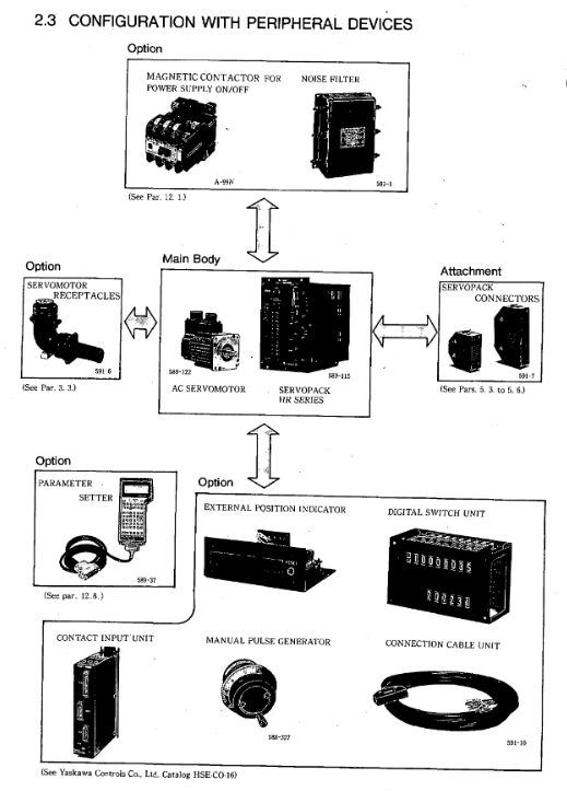
Main circuit connection: three-phase/single-phase power supply → circuit breaker (MCCB) → noise filter → servo driver (R/S/T) → motor (U/V/W).
Control circuit connection:
I/O signals: 2CN (servo enable SVON, start AST), 5CN (manual operation MCW/MCCW);
Encoder: 3CN (A/B/C phase signals,+5V power supply);
Serial communication: 4CN (TXD/RXD, RS422 protocol).
2. Definition of Key Terminals (Taking 2CN as an Example)
Terminal number, signal name, type, and function
8 SVON input servo enable, main circuit transistor unlocked when ON, motor powered on
Automatic operation/zeroing start with 16 AST inputs, valid rising edge, must be maintained for ≥ 5ms
15 STOP input temporarily stops, when ON, the motor decelerates and stops according to the parameter settings
11 ALM output fault alarm, transistor cutoff during fault (normally ON)
12 BK output brake release, when servo ON, ON, release motor brake
3. Wiring specifications
Cable selection:
Main circuit: 1.25-8mm ² copper core wire (e.g. 8mm ² for HR60BB);
Signal circuit: 0.2mm ² shielded twisted pair (DP8409123 and other dedicated wires are used for encoder lines).
- ABB
- General Electric
- EMERSON
- Honeywell
- HIMA
- ALSTOM
- Rolls-Royce
- MOTOROLA
- Rockwell
- Siemens
- Woodward
- YOKOGAWA
- FOXBORO
- KOLLMORGEN
- MOOG
- KB
- YAMAHA
- BENDER
- TEKTRONIX
- Westinghouse
- AMAT
- AB
- XYCOM
- Yaskawa
- B&R
- Schneider
- Kongsberg
- NI
- WATLOW
- ProSoft
- SEW
- ADVANCED
- Reliance
- TRICONEX
- METSO
- MAN
- Advantest
- STUDER
- KONGSBERG
- DANAHER MOTION
- Bently
- Galil
- EATON
- MOLEX
- DEIF
- B&W
- ZYGO
- Aerotech
- DANFOSS
- Beijer
- Moxa
- Rexroth
- Johnson
- WAGO
- TOSHIBA
- BMCM
- SMC
- HITACHI
- HIRSCHMANN
- Application field
- XP POWER
- CTI
- TRICON
- STOBER
- Thinklogical
- Horner Automation
- Meggitt
- Fanuc
- Baldor
- SHINKAWA
- Other Brands


