
Yaskawa VARISPEED-626M5 frequency converter
Voltage level and power range:
Voltage level, power range, and motor compatibility
200V level 3.7kW-37kW (5HP-50HP) 50Hz/60Hz three-phase AC motor
400V class 5.5kW-45kW (7.5HP-60HP) 50Hz/60Hz three-phase AC motor
Core control features: sine wave PWM vector control, supporting speed/torque control, servo mode optional
Yaskawa VARISPEED-626M5 frequency converter
Product Overview
1. Core positioning and model
Product type: VARISPEED-626M5 frequency converter (vector control)+VS-656MR5 power regeneration converter, specializing in high-precision drive of industrial motors
Voltage level and power range:
Voltage level, power range, and motor compatibility
200V level 3.7kW-37kW (5HP-50HP) 50Hz/60Hz three-phase AC motor
400V class 5.5kW-45kW (7.5HP-60HP) 50Hz/60Hz three-phase AC motor
Core control features: sine wave PWM vector control, supporting speed/torque control, servo mode optional
2. Key performance parameters
Speed regulation performance: Speed regulation range from 40r/min to the maximum motor speed (up to 8000r/min), speed accuracy ≤ 0.2% (rated speed)
Overload capacity: 120% rated current/1 minute, 200% rated current/1 second (converter)
Control response: Soft start time adjustable from 0.1-180 seconds, fast torque response (optimized through proportional gain/integral time parameters)
Protection functions: 20+protections for overcurrent, overvoltage, undervoltage, overheating, motor overload, encoder failure, etc
Installation and wiring specifications
1. Installation requirements
Environmental conditions: temperature 0-55 ℃ (inlet temperature of heat sink ≤ 45 ℃), humidity 5% -95% (no condensation), altitude ≤ 1000m
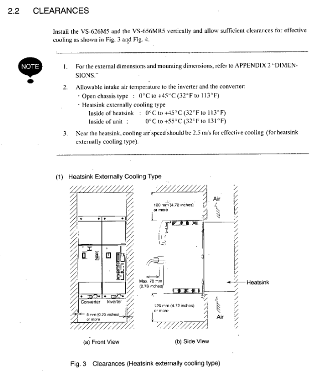
Installation method: Vertical installation, cooling distance requirement:
External heat sink type: front and rear ≥ 120mm, left and right ≥ 5mm
Open chassis type: front and back ≥ 150mm, left and right ≥ 50mm
Protection level: IEC IP00, indoor installation (anti-corrosion gas, dust)
2. Core wiring specifications
Main circuit wiring:
Power side: MCCB (molded case circuit breaker) and AC reactor (harmonic suppression) must be connected in series
Output side: It is strictly prohibited to connect AC power supply or phase advance capacitor, with a wiring length of ≤ 20m
Grounding: Dedicated grounding terminal, independent grounding (not shared with high current equipment), grounding resistance ≤ 10 Ω (400V level)/≤ 100 Ω (200V level)
Control circuit wiring:
Signal types: analog (0 ± 10V speed command), digital (forward/reverse, emergency stop, etc.), encoder signal (RS-422A)
Wiring requirements: The distance from the main circuit should be ≥ 30cm, shielded twisted pair cables should be used, and the shielding layer should be grounded at one end
Operation and control functions
1. Operation mode and control mode
Operating modes: FWD (Forward Rotation), REV (Reverse Rotation), Jog (JOG, 5% rated speed), SV (Servo Mode), CHW (Winding Switching), Positioning Stop
Control method:
Control mode, signal type, core parameters
Analog control 0 ± 10V voltage signal input impedance 50k Ω, high resolution
Digital quantity control 12 bit BCD/binary supports 8 levels of internal speed settings (C1-41-C1-48)
The local control digital operator (JVOP-132) supports parameter modification, fault reset, and jog operation
2. Key operational procedures
Start up process: Control power supply → Main circuit power supply → Run command → Slowly increase speed command
Debugging steps:
Power on self-test (7-segment LED displays "- b" as ready)
Motor steering inspection (motor rotates counterclockwise under forward rotation command)
Speed response test (smoothness of acceleration/deceleration)
Protection function verification (overload, emergency stop test)
Parameter settings: The core parameters include rated speed (C1-26), speed proportional gain (C1-01), and soft start time (C1-10). Some parameter modifications require a power outage and restart to take effect
Maintenance and troubleshooting
1. Regular maintenance plan
Replacement cycle of vulnerable parts:
Remarks on component replacement cycle
Check the cooling fan after running for 20000 hours in 2-3 years
Smooth capacitor 5-year inspection for bulging and leakage
Electrolytic capacitor (control board) with a 5-year adjustment cycle based on ambient temperature
Motor bearings lubricated or replaced as needed after 12000 hours/2 years
Daily inspection: tightening of terminal screws, cleaning of heat sinks (blowing with compressed air), insulation of cables
2. Fault diagnosis system
Fault display: 7-segment LED alternately displays the fault occurrence number and fault code (such as "2-01" indicating that the second fault is overcurrent)
Common faults and solutions:
Fault code, fault name, handling measures
AL-C1 overcurrent inspection for motor short circuit, loose wiring, and load overload
AL-11 main circuit overvoltage check input voltage, regenerative braking circuit
AL-30 encoder signal disconnection inspection encoder wiring, shielding layer grounding
AL-42 motor thermistor disconnection check motor temperature and thermistor wiring
Fault record: The frequency converter can store 6 fault records, which can be viewed through the operator and need to be manually cleared
Application and adaptation scenarios
Typical applications: Machine tool spindle drive, industrial machinery transmission system
Adapt to peripheral devices:
Detection components: incremental encoder (RS-422A interface), magnetic sensor
Protective components: MCCB, magnetic contactor, AC reactor (model UZBA-B series)
- OMRON
- ABB
- General Electric
- EMERSON
- Honeywell
- HIMA
- ALSTOM
- Rolls-Royce
- MOTOROLA
- Rockwell
- Siemens
- Woodward
- YOKOGAWA
- FOXBORO
- KOLLMORGEN
- MOOG
- KB
- YAMAHA
- BENDER
- TEKTRONIX
- Westinghouse
- AMAT
- AB
- XYCOM
- Yaskawa
- B&R
- Schneider
- KONGSBERG
- NI
- WATLOW
- ProSoft
- SEW
- ADVANCED
- Reliance
- TRICONEX
- METSO
- MAN
- Advantest
- STUDER
- DANAHER MOTION
- Bently
- Galil
- EATON
- MOLEX
- DEIF
- B&W
- ZYGO
- Aerotech
- DANFOSS
- Beijer
- Moxa
- Rexroth
- Johnson
- WAGO
- TOSHIBA
- BMCM
- SMC
- HITACHI
- HIRSCHMANN
- Application field
- XP POWER
- CTI
- TRICON
- STOBER
- Thinklogical
- Horner Automation
- Meggitt
- Fanuc
- Baldor
- SHINKAWA
- Other Brands
- UniOP
- KUKA
- Iba
- Beckhoff
-
 Basler DECS-200-2L Digital Excitation Control
 -
 Basler BE1-47N Voltage Phase Sequence Relay
 -
 Basler AEC63-7 Analog Excitation Controller 220-277V
 -
 Basler BE1-50/51B-107 Overcurrent Relay
 -
 Basler Electric BE1‑32R BE1‑E1P‑BON0F Protective Relay
 -
 Basler BE1-25 Solid State Time Overcurrent Relay M1EA6PA5S1F
 -
 Basler MVC 232 Manual Voltage Control Module 90 37000 103 60VAC 55VDC
 -
 Basler RAL6144-16GM Racer GigE Line Scan Camera
 -
 Basler SSR 63-12 Static Voltage Regulator
 -
 Basler BE1-51A Overcurrent Relay
 -
 Basler BE1-87T Solid State Protective Relay
 -
 Basler SR4A2B01B3A Static Voltage Regulator
 -
 Basler SSR 32-12 Static Voltage Regulator
 -
 Basler TRR00696 Transformer 1KVA 115V
 -
 Basler DECS-100-B15 AVR Replacement
 -
Basler BE1-27 Under-Voltage Relay
-
 Basler ACA2000-50GM Interface Module
 -
 Basler AEC63-7 Analog Excitation Controller
 -
 Basler PRS 250 Veri-Sync Relay
 -
 Basler SR4A-2B15B3A Static Voltage Regulator
 -
Basler BE1-32R Power Relay
-
Basler SR8A-2B06B3E Static Voltage Regulator
-
Basler BE1-81 O/U Frequency Relay
-
 Basler BE1-51A-K2E-W6M-B1N0F Overcurrent Relay
 -
Basler BE1-851 Overcurrent Relay G3A1S1 – 48-125V AC/DC
-
 Basler BEI-51 Overcurrent Relay – NSN 5945-01-293-2363
 -
Basler Electric L301KC Protective Relay – L301KC
-
 Basler DECS-100-B15 Automatic Voltage Regulator – Generator AVR
 -
 Basler SR4A-2B15B3A Static Voltage Regulator – SR4A2B15B3A
 -
 Basler UF 312 Under Frequency Protective Module – 9094700100
 -
Basler Electric MVC 232 Manual Control Module – 60VAC 55VDC 20A
-
Basler PRS 250 Veri-Sync Relay – Generator Synchronizing Relay
-
 Basler DECS-100-A05 Digital Regulator Review
 -
 Basler AEM-2020 Analog Expansion Module Specs
 -
 Basler DECS-100-B15 Digital Excitation Specs
 -
Basler Electric 9125600106 Regulator Component
-
Basler BE1-51A-K1E-W6M-B1N0F Overcurrent Relay
-
 Basler MVC-301 MVC 300 Excitation Controller
 -
 Basler SSR 32-12 Static Voltage Regulator
 -
 Basler 9-2849-00-101 Control Module
 -
Basler BE1-51A Overcurrent Relay
-
 Basler BE1-51/27R Overcurrent Relay
 -
 Basler BE1-51 Overcurrent Relay
 -
 Basler SR8A-2B15B3A Static Voltage Regulator
 -
 Basler BE32965001 Transformer and Timer Board
 -
 Basler 9174700100 EL200-7 Excitation Limiter
 -
 Basler BE2000E AVR Voltage Regulator
 -
Basler BE1-87G Differential Relay
-
 Basler BE21834001 Generator Control Module
 -
Basler DECS-100-B15 AVR
-
 Basler D90 96801 100 PCB Card
 -
 Basler XR2002F Voltage Regulator (110 VAC, 48-480 Hz)
 -
 Basler SR8A-2B14B3A Regulator
 -
 Basler 9561500100 Module
 -
 Basler DECS-400 BE1-11 System
 -
 Basler DECS-100-B15 Excitation Control
 -
 Basler SCP 210 Frequency Controller
 -
Basler SR4A-2B15B3A Static Voltage Regulator
-
Basler BE1-32R Power Relay
-
 Basler PIA2400-17GM Power Interface Adapter
 -
 Basler MVC 232 Manual Voltage Control Module
 -
 Basler SSR 32-12 Static Voltage Regulator
 -
Basler 5MW AVR Generator Voltage Regulator
-
 Basler VR63-4B Voltage Regulator
 -
Basler DECS-100-A05 AVR for Engine Generator
-
Basler DECS-100-B15 Automatic Voltage Regulator
-
Basler BE1-32R Directional Power Relay
-
Basler BE1-87B Differential Relay
-
 Basler UFOV 260A Protective Module
 -
 Basler 9-2614-02-100 PCB Rev M
 -
Basler DECS-100-B15 Digital AVR
-
 Basler 9284900103 PS DECS-400N
 -
 Basler D4N3H1U Intertie Protection
 -
 Basler DECS-100-B15 A15 AVR
 -
 Basler KR4F Voltage Regulator
 -
 Basler BE26434 T14 Transformer
 -
 Basler SR8A-2B15B3A Regulator
 -
 Westinghouse 774B472A12 AR Relay
 -
Basler DECS-100-B15 AVR
-
Basler XR2002F Regulator 110V
-
Basler SR125-E Static Regulator
-
Basler SSR 125-12 Regulator
-
Basler MOC2599 Motor Pot
-
 Basler BE1-DFPR Feeder Relay
 -
 Basler CBS 305 Current Boost
 -
Basler BE1-25 AutoSync
-
Basler MVC 300 Voltage Control
-
 Basler BE3-25A AutoSync
 -
 Basler KR7FF Static Regulator
 -
Basler 90-49000-100 Regulator
-
 Basler 880 kVA Dry Type Transformer Specs
 -
Basler Electric BE1-25 Sync-Check Relay Specs
-
 Basler SSR 125-12 Voltage Regulator Specs
 -
 Basler Electric BE1-851 Overcurrent Relay Review
 -
Basler Electric 149D930G02 Control Sub-Assembly
-
 Basler Electric BE1-81O/UT Frequency Relay Specs
 -
 Basler Electric BE1-51/27C Overcurrent Relay
 -
 Basler Electric 149D956G02 Industrial Component
 -
Basler Electric BE1-51A Overcurrent Relay Specs
-
 Basler Electric BE1-40Q Loss of Excitation Relay
 -
Basler DECS-200 Excitation Control System
-
 Basler DECS-200 Voltage Regulator 56-277V AC / 125V DC
 -
Basler BE1-87T Transformer Differential Relay
-
 Basler RDP-110-S1 Protection Relay
 -
 Basler BE1-700V Digital Protective Relay
 -
 Basler BE1-951 Overcurrent Protection System
 -
 Basler DECS-300 Digital Excitation Control
 -
 Basler DECS-200 Digital Excitation Control
 -
 Basler DECS-200-1C Excitation Control System
 -
Basler DECS-200-1L Digital Excitation Control
-
 Basler Electric BE1-GPS Generator Protection System
 -
Basler Electric DECS-200-1C Digital Excitation Controller
-
 Basler Electric DECS125-15 Excitation Control with Power Module
 -
Basler Electric BE1-87G Differential Relay
-
 Basler Electric BE1-11 Protection System I5A3M2P2N0EA00
 -
Basler Electric DECS-200-1C Excitation Control System
-
Basler Electric BE1-11g Generator Protection Relay
-
Basler Electric DECS 125-15-B2C1 V2.0.9 Excitation Control
-
Basler Electric BE1-81O/UT3ED1JA7N2F Frequency Relay
-
Basler Electric BE1-81O/UT3EE1YB7N1F Frequency Relay
-
 Basler Electric DECS-200-1L Digital Excitation Control System
 -
Basler DECS125-15-B2C1 Excitation Control
-
 Basler 9507900205 SSR Retrofit Voltage Regulator
 -
 Basler BE2000E Digital Voltage Regulator
 -
 Basler BE1-GPS Generator Protection System
 -
Basler DECS-250-CN1CN1N Digital Excitation Control
-
 Basler DGC-2020 Genset Controller
 -
Basler BE1-81O UT3ED1LA7N0F Frequency Relay (Variant)


