
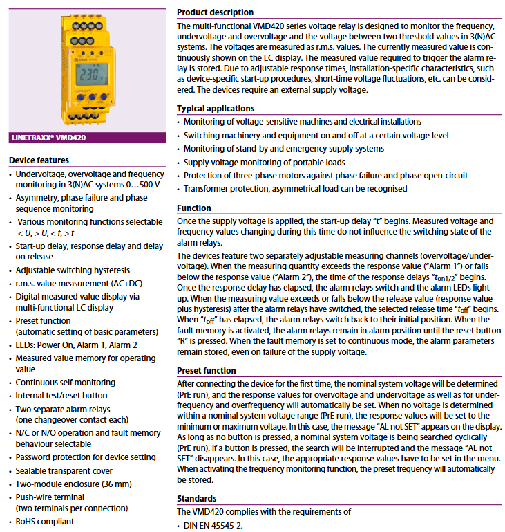
BENDER LINETRAXX ® VMD420 Three phase Voltage Frequency Monitor
BENDER LINETRAXX ® VMD420 Three phase Voltage Frequency Monitor
Product Overview
LINETRAXX ® VMD420 is a multifunctional voltage frequency monitor launched by BENDER, designed specifically for 3 (N) AC systems. Its core is used to monitor voltage (under voltage, over voltage), frequency (under frequency, over frequency), and phase related parameters (phase sequence, phase loss, asymmetry). The measurement voltage range covers 0... 500 V (L-L)/0... 288 V (L-N), and the frequency range is 15... 460 Hz. It adopts true RMS (AC+DC) measurement method to ensure data accuracy. The product complies with CE, DIN EN 45545-2, and IEC series standards, with high reliability and industrial grade protection performance, suitable for various electrical safety monitoring scenarios.
Core functions and features
(1) Comprehensive monitoring function
Voltage monitoring: It can simultaneously achieve undervoltage (U<) and overvoltage (U>) monitoring, with a monitoring range of AC 6... 500 V (3AC system, L-L wiring) or AC 6... 288 V (3 (N) AC system, L-N wiring), with a voltage setting resolution of 1 V, which can meet high-precision monitoring requirements. The device has a built-in preset function that automatically configures response values for different rated voltage systems: in the 3AC system, when the rated voltage Un is 400 V, the undervoltage preset value is 340 V (0.85Un) and the overvoltage preset value is 440 V (1.1Un); In the 3 (N) AC system, when Un is 230 V, the preset undervoltage value is 196 V and the preset overvoltage value is 253 V, without the need for manual configuration.
Frequency monitoring: Supports under frequency (<f) and over frequency (>f) monitoring, with a frequency setting range of 10... 500 Hz, where the resolution of the 10.0... 99.9 Hz interval is 0.1 Hz and the resolution of the 100... 500 Hz interval is 1 Hz, ensuring accurate capture of frequency fluctuations. The preset function is also applicable to frequency monitoring, with corresponding underfrequency and overfrequency preset values configured for rated frequencies of 16.7 Hz, 50 Hz, 60 Hz, and 400 Hz (such as 50 Hz corresponding to underfrequency of 49 Hz and overfrequency of 51 Hz), suitable for different power supply scenarios.
Phase related monitoring: including phase sequence, phase loss, and voltage asymmetry monitoring. Phase sequence monitoring supports recognition of two rotation directions: clockwise and counterclockwise. It is set to off by default and can be turned on according to actual system requirements; Phase loss is indirectly identified through voltage asymmetry threshold. When the three-phase voltage asymmetry exceeds the set value, an alarm is triggered; The asymmetric monitoring range is 5... 30%, and the factory defaults to 30%. It can be adjusted according to the system load characteristics to effectively prevent equipment damage caused by three-phase imbalance.
Measurement accuracy: The relative error of voltage measurement at 50/60 Hz power frequency is only ± 1.5% (± 2 digits), and the relative error within a wide frequency range of 15... 460 Hz is ± 3% (± 2 digits); The relative error of frequency measurement within the range of 15... 460 Hz is only ± 0.2% (± 1 digit), and high-precision measurement ensures the accuracy of alarm triggering, avoiding false alarms or missed alarms.
(2) Flexible time parameter configuration
Start delay (t): Set the range to 0... 300 seconds, with the factory default of 0 seconds. This function can avoid false alarms caused by unstable voltage and frequency during the device's power on start-up phase, and adapt to electrical characteristic fluctuations during the device's start-up process.
Response delay (ton1/2): Adjustable for two alarm channels, with a range of 0... 300 seconds and a default of 0 seconds. The delay time can be set according to the short-term fluctuations in on-site voltage and frequency, filtering out instantaneous interference signals and ensuring the reliability of alarm triggering.
Release delay (toff): Set the range from 0 to 300 seconds, with a default of 0.5 seconds. When the monitoring parameters return to the normal range (response value ± hysteresis), the device will not immediately reset, but will switch back to the initial state after a release delay to prevent frequent relay actions caused by repeated parameter fluctuations.
Action and recovery speed: The action time of voltage signal is ≤ 140 ms, and the action time of frequency signal is ≤ 335 ms, with rapid response and the ability to capture faults and trigger protection in a timely manner; The equipment recovery time is ≤ 300 ms, and after troubleshooting, it can quickly restore normal monitoring status.
(3) Display and storage functions
Display module: equipped with a multifunctional non luminous LC display screen, which can display the current measured voltage and frequency values in real time (display range 0... 500 V), and can also display device setting parameters, alarm status and other information. The interface is simple and intuitive, making it easy to view on site.
Storage function: equipped with running value memory function, which can record key parameters of the device during normal operation; Historical Memory (HiS) can store the measurement values at the first alarm, providing data support for troubleshooting; Fault memory supports three modes: on, off, and on. It is enabled by default. When set to continuous mode, even if the power supply is interrupted, the alarm parameters will still be retained, and historical fault information can be viewed after power supply is restored.
(4) Safety and operational assurance
Protection mechanism: The device supports password protection function, with a password range of 0... 999. It is disabled by default and can prevent unauthorized personnel from modifying device parameters when enabled; Equipped with a sealed transparent cover, it can protect the internal operating components, facilitate the viewing of equipment status, and meet the requirements of dust prevention and misoperation prevention; Equipped with continuous self-monitoring function, it can detect the working status of the equipment in real time. If there is a fault, it will be promptly reported through alarm lights and relays.
Operation buttons: including three core buttons: Test (T), Reset (R), and Menu (MENU). The functional reuse design balances convenience and integration:
Test key (T): Short press to switch the display of measurement values, and the menu can switch options up or modify parameters; Long press (>1.5 s) to activate the self-test function.
Reset button (R): Short press to switch the display of measurement values, and the menu can be used to switch down options or modify parameters; Long press (>1.5 s) to clear stored alarm records.
MENU: Short press to confirm, used to confirm the displayed measurement values or modified parameters; Long press (>1.5 s) to call up the menu system; Long press the ESC function (>1.5 seconds) to abort the current operation or return to the previous menu.
Indicator light status: Power light (ON, green): Always on when power supply is normal, flashing when system fault alarm is triggered; Alarm lights (AL1, AL2, yellow): keep on when triggered by corresponding alarm relays K1 and K2, and flash when the system fails; The indicator light status can quickly determine the working status and alarm situation of the equipment.
(5) Alarm output configuration
The equipment is equipped with two independent alarm relays (K1, K2), each designed with a single conversion contact, supporting switching between normally closed (N/C) or normally open (N/O) operating modes to meet different control circuit requirements.
The configurable monitoring types of relays include: Err, U<, U>, Asy, Hz<, Hz>, PHS, and S.AL. The factory default configuration is:
K1: Overvoltage (U>), asymmetry (Asy), normally open (N/O) mode.
K2: Under voltage (U<), asymmetric (Asy), normally closed (N/C) mode.
The electrical life of the relay reaches 10000 cycles, and the contact parameters comply with the IEC 60947-5-1 standard. The rated parameters under different usage categories are as follows:
Usage category: Rated voltage, rated current
AC-13 230 V 5 A
AC-14 230 V 3 A
DC-12 24 V 1 A
DC-12 110 V 0.2 A
DC-12 220 V 0.1 A
The minimum contact load is 1 mA when AC/DC ≥ 10 V, ensuring reliable operation in low load scenarios.
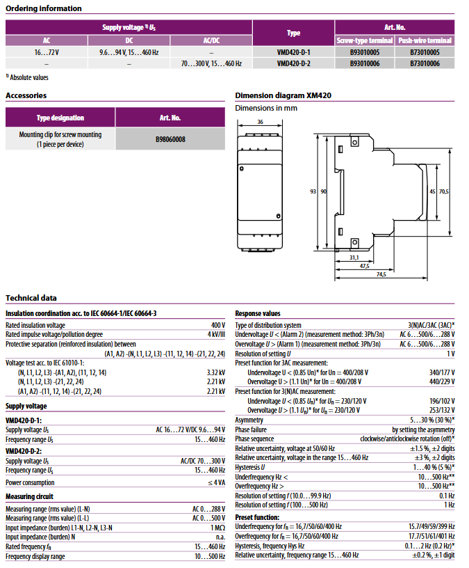
Model specifications and ordering information
(1) Core model parameters
The equipment is divided into two core models according to the power supply voltage, and each model provides two wiring options: screw terminals and push in terminals. The specific parameters are as follows:
Model Supply Voltage (Us) Frequency Range Terminal Type Product Number (Art. No.)
VMD420-D-1 AC 16... 72 V/DC 9.6... 94 V 15... 460 Hz screw terminal B93010005
Push in terminal B73010005
VMD420-D-2 AC/DC 70... 300 V 15... 460 Hz screw terminal B93010006
Push in terminal B73010006
Note: The power supply voltage is the absolute rated value, and actual use should be within the specified range to avoid overvoltage or undervoltage operation.
(2) Accessory information
Accessory Name Usage Product Number (Art. No.)
Fixed clamp for screw installation (1 per device) used for fixing equipment screws B98060008
Key technical parameters
(1) Insulation and voltage resistance performance
Project parameter specifications
Rated insulation voltage 400 V
Rated impulse voltage/pollution level 4 kV/III
Protective isolation (strengthened insulation) between A1, A2 and N, L1, L2, L3, 11, 12, 14, 21, 22, 24
Voltage withstand test (IEC 61010-1) (N, L1, L2, L3) and (A1, A2), (11,12,14): 3.32 kV
(N, L1, L2, L3) and (21,22,24): 2.21 kV
(A1, A2) and (11,12,14), (21,22,24): 2.21 kV
(2) Power supply and power consumption
Model Supply Voltage Range Frequency Range Power Consumption
VMD420-D-1 AC 16…72 V / DC 9.6…94 V 15…460 Hz ≤ 4 VA
VMD420-D-2 AC/DC 70…300 V 15…460 Hz ≤ 4 VA
(3) Measure circuit parameters
Project parameter specifications
Measurement range (true RMS) - L-N AC 0... 288 V
Measurement range (true RMS) - L-L AC 0... 500 V
Input impedance (L1-N, L2-N, L3-N) 1 M Ω
Input impedance (N line) None (n.a.)
Rated frequency (fn) 15... 460 Hz
Frequency display range 10... 500 Hz
(4) Environment and EMC Performance
Electromagnetic compatibility (EMC): Complies with EN 61326-1 standard, has strong resistance to electromagnetic interference, and is suitable for complex industrial electromagnetic environments.
Temperature range:
Working temperature: -25...+55 ℃
Transportation temperature: -25...+70 ℃
Storage temperature: -25...+55 ℃
Classification of climatic conditions (IEC 60721):
Fixed use (3K23): no condensation, no icing
Transportation (2K11, 1K22)
Long term storage (1K12)
Classification of mechanical conditions (IEC 60721):
Fixed use (3M11)
Transportation (2M4)
Long term storage (1M12)
Optional version (Option "W"): Designed for special climate environments, allowing condensation and freezing during fixed use (climate classification 3K23), mechanical condition classification 3M12, suitable for extreme scenarios such as high humidity and low temperature.
(5) Wiring parameters
The device supports two wiring methods: screw terminals and push in terminals. The specific wiring requirements are as follows:
Screw terminal:
Rigid wire: 0.2... 4 mm ² (AWG 24... 12)
Flexible wire: 0.2... 2.5 mm ² (AWG 24... 14)
Two rigid/flexible wires with the same cross-section: 0.2... 1.5 mm ² (AWG 24... 16)
Wire stripping length: 8-9 mm
Tightening torque of terminal screw: 0.5... 0.6 Nm
Push in terminal:
Rigid wire: 0.2... 2.5 mm ² (AWG 24... 14)
Flexible wire without cold press joint: 0.75... 2.5 mm ² (AWG 19... 14)
Flexible wire with cold press joint: 0.2... 1.5 mm ² (AWG 24... 16)
Wire stripping length: 10mm
Terminal opening force: 50 N
Test opening diameter: 2.1 mm
(6) Other physical and installation parameters
Project parameter specifications
Continuous operation in working mode
Installation method at any position (guide rail/screw)
Protection level (internal components/terminals) IP30/IP20 (DIN EN 60529)
Shell material polycarbonate
Flame retardant grade UL94 V-0
Rail installation standard IEC 60715
Screw installation requirements: 2 x M4 screws+fixing clip
Shell dimensions (width x height x depth) 36 mm x 93 mm x 90 mm
Weight ≤ 150 g
Working principle
(1) Basic workflow
After the device is connected to the external power supply voltage (A1, A2 terminals), the start delay (t) starts timing. During this stage, fluctuations in voltage and frequency will not affect the switching status of the alarm relay, ensuring stable device startup.
After the startup delay is over, the device enters the normal monitoring state, collects the voltage and frequency signals of the monitored system through terminals L1, L2, L3, and N, and calculates the true effective value and related parameters in real time.
When the monitoring parameters exceed (or fall below) the set response value, the response delay (ton1/2) of the corresponding alarm channel is activated; If the parameter remains in an over limit state during the response delay period, the corresponding alarm relay (K1/K2) will activate and the corresponding alarm light (AL1/AL2) will light up after the response delay ends.
After the alarm is triggered, if the monitoring parameters return to the release value (response value ± switching delay), the release delay (toff) will be activated; After the release delay is completed, the alarm relay resets and the alarm light goes out.
If the fault memory function is enabled, the alarm relay will remain in the alarm state until the reset button (R) is pressed to clear the alarm; If set to continuous fault memory mode, the alarm state will still be retained even if the power supply is interrupted.
(2) Preset function (PrE run)
After the device is first connected to the power supply, it automatically starts the preset function, detects the rated voltage (Un) of the system, and automatically configures the response values for undervoltage, overvoltage, underfrequency, and overclocking based on the detection results.
If no effective rated voltage is detected during the preset process (beyond the normal voltage range), the device will set the response value to the minimum or maximum limit value, and the display screen will show "AL not SET".
When no button is pressed, the device will cycle to search for the rated voltage (continuous PrE run); If any button is pressed, the search process will be interrupted and the "AL not SET" prompt will disappear. At this time, the response parameters need to be manually configured through the menu.
When the frequency monitoring function is enabled, the preset function will automatically store the rated frequency of the current system and configure the corresponding underfrequency and overfrequency response values.
(3) Line protection requirements
According to the IEC 60364-4-43 standard, it is recommended to install 6A fuses for overcurrent protection in the equipment circuit; If the equipment is powered by the IT system, fuses need to be installed on both power lines to ensure power supply safety.
Typical application scenarios
Voltage sensitive equipment monitoring: used for power supply circuits of precision instruments, PLC controllers, industrial automation equipment, and other equipment that are sensitive to voltage fluctuations. Real time monitoring of voltage and frequency changes to avoid equipment damage or data loss caused by undervoltage, overvoltage, and frequency abnormalities.
Mechanical equipment start stop control: Based on the set voltage threshold, automatically control the start stop of machinery and production equipment. For example, when the power supply voltage returns to the normal range and stabilizes for a period of time, the equipment will automatically start; When the voltage is abnormal, promptly cut off the power supply of the equipment to protect it from impact.
Backup/Emergency Power Supply System Monitoring: Monitor the output voltage and frequency of backup power supply systems such as UPS power supply and diesel generators to ensure stable and reliable power supply after the backup power supply is started, ensuring the continuous operation of critical loads such as emergency lighting, fire equipment, and data centers.
Three phase motor protection: For equipment such as three-phase asynchronous motors, monitor the phase sequence, phase loss, and voltage asymmetry to prevent motor reversal due to phase sequence errors, or motor overheating or burnout due to phase loss or three-phase imbalance, thereby extending the service life of the motor.
Transformer protection: By monitoring the asymmetry of the secondary voltage of the transformer, identifying the asymmetric load state of the transformer, avoiding local overheating and increased losses caused by load imbalance, and ensuring the safe and stable operation of the transformer.
Portable load power supply monitoring: used for power supply circuits of portable loads such as mobile devices and temporary construction equipment, to monitor the stability of power supply voltage, timely detect power supply faults, and prevent equipment damage due to power supply problems in outdoor or temporary scenarios.
- OMRON
- ABB
- General Electric
- EMERSON
- Honeywell
- HIMA
- ALSTOM
- Rolls-Royce
- MOTOROLA
- Rockwell
- Siemens
- Woodward
- YOKOGAWA
- FOXBORO
- KOLLMORGEN
- MOOG
- KB
- YAMAHA
- BENDER
- TEKTRONIX
- Westinghouse
- AMAT
- AB
- XYCOM
- Yaskawa
- B&R
- Schneider
- KONGSBERG
- NI
- WATLOW
- ProSoft
- SEW
- ADVANCED
- Reliance
- TRICONEX
- METSO
- MAN
- Advantest
- STUDER
- DANAHER MOTION
- Bently
- Galil
- EATON
- MOLEX
- DEIF
- B&W
- ZYGO
- Aerotech
- DANFOSS
- Beijer
- Moxa
- Rexroth
- Johnson
- WAGO
- TOSHIBA
- BMCM
- SMC
- HITACHI
- HIRSCHMANN
- Application field
- XP POWER
- CTI
- TRICON
- STOBER
- Thinklogical
- Horner Automation
- Meggitt
- Fanuc
- Baldor
- SHINKAWA
- Other Brands
- UniOP
- KUKA
- Iba
- Beckhoff
-
 Basler D90 96801 100 PCB Card
 -
 Basler XR2002F Voltage Regulator (110 VAC, 48-480 Hz)
 -
 Basler SR8A-2B14B3A Regulator
 -
 Basler 9561500100 Module
 -
 Basler DECS-400 BE1-11 System
 -
 Basler DECS-100-B15 Excitation Control
 -
 Basler SCP 210 Frequency Controller
 -
 Basler SR4A-2B15B3A Static Voltage Regulator
 -
 Basler BE1-32R Power Relay
 -
 Basler PIA2400-17GM Power Interface Adapter
 -
 Basler MVC 232 Manual Voltage Control Module
 -
 Basler SSR 32-12 Static Voltage Regulator
 -
 Basler 5MW AVR Generator Voltage Regulator
 -
 Basler VR63-4B Voltage Regulator
 -
 Basler DECS-100-A05 AVR for Engine Generator
 -
 Basler DECS-100-B15 Automatic Voltage Regulator
 -
 Basler BE1-32R Directional Power Relay
 -
 Basler BE1-87B Differential Relay
 -
 Basler UFOV 260A Protective Module
 -
 Basler 9-2614-02-100 PCB Rev M
 -
Basler DECS-100-B15 Digital AVR
-
 Basler 9284900103 PS DECS-400N
 -
 Basler D4N3H1U Intertie Protection
 -
 Basler DECS-100-B15 A15 AVR
 -
 Basler KR4F Voltage Regulator
 -
 Basler BE26434 T14 Transformer
 -
 Basler SR8A-2B15B3A Regulator
 -
 Westinghouse 774B472A12 AR Relay
 -
Basler DECS-100-B15 AVR
-
Basler XR2002F Regulator 110V
-
Basler SR125-E Static Regulator
-
 Basler SSR 125-12 Regulator
 -
 Basler MOC2599 Motor Pot
 -
 Basler BE1-DFPR Feeder Relay
 -
 Basler CBS 305 Current Boost
 -
 Basler BE1-25 AutoSync
 -
 Basler MVC 300 Voltage Control
 -
 Basler BE3-25A AutoSync
 -
 Basler KR7FF Static Regulator
 -
 Basler 90-49000-100 Regulator
 -
 Basler 880 kVA Dry Type Transformer Specs
 -
 Basler Electric BE1-25 Sync-Check Relay Specs
 -
 Basler SSR 125-12 Voltage Regulator Specs
 -
 Basler Electric BE1-851 Overcurrent Relay Review
 -
Basler Electric 149D930G02 Control Sub-Assembly
-
 Basler Electric BE1-81O/UT Frequency Relay Specs
 -
 Basler Electric BE1-51/27C Overcurrent Relay
 -
 Basler Electric 149D956G02 Industrial Component
 -
Basler Electric BE1-51A Overcurrent Relay Specs
-
 Basler Electric BE1-40Q Loss of Excitation Relay
 -
 Basler DECS-200 Excitation Control System
 -
 Basler DECS-200 Voltage Regulator 56-277V AC / 125V DC
 -
Basler BE1-87T Transformer Differential Relay
-
 Basler RDP-110-S1 Protection Relay
 -
 Basler BE1-700V Digital Protective Relay
 -
 Basler BE1-951 Overcurrent Protection System
 -
 Basler DECS-300 Digital Excitation Control
 -
 Basler DECS-200 Digital Excitation Control
 -
 Basler DECS-200-1C Excitation Control System
 -
Basler DECS-200-1L Digital Excitation Control
-
 Basler Electric BE1-GPS Generator Protection System
 -
Basler Electric DECS-200-1C Digital Excitation Controller
-
 Basler Electric DECS125-15 Excitation Control with Power Module
 -
 Basler Electric BE1-87G Differential Relay
 -
 Basler Electric BE1-11 Protection System I5A3M2P2N0EA00
 -
Basler Electric DECS-200-1C Excitation Control System
-
Basler Electric BE1-11g Generator Protection Relay
-
Basler Electric DECS 125-15-B2C1 V2.0.9 Excitation Control
-
 Basler Electric BE1-81O/UT3ED1JA7N2F Frequency Relay
 -
Basler Electric BE1-81O/UT3EE1YB7N1F Frequency Relay
-
 Basler Electric DECS-200-1L Digital Excitation Control System
 -
Basler DECS125-15-B2C1 Excitation Control
-
 Basler 9507900205 SSR Retrofit Voltage Regulator
 -
 Basler BE2000E Digital Voltage Regulator
 -
 Basler BE1-GPS Generator Protection System
 -
Basler DECS-250-CN1CN1N Digital Excitation Control
-
 Basler DGC-2020 Genset Controller
 -
 Basler BE1-81O UT3ED1LA7N0F Frequency Relay (Variant)
 -
 Basler BE1-81O UT3EE1YA9S0F Frequency Relay (Variant)
 -
Basler BE1-81O Over/Under Frequency Relay
-
Basler DECS125-15 Digital Excitation Control
-
Basler Electric BE1-951 Overcurrent Protection System
-
 Basler Electric BE1-700V Digital Protective Relay
 -
 Basler Electric APR63-5 Automatic Voltage Regulator
 -
Basler Electric BE1-851 Overcurrent Protection System
-
Basler Electric DECS-250-LN1SN1N Excitation Control
-
 Basler Electric BE1-87T Transformer Differential Relay
 -
Basler Electric DECS-200-1L Excitation Control System
-
 Basler Electric 9310300100 DECS-300 Excitation Control
 -
 Basler Electric SSE-N 125-4.5KW Shunt Exciter Regulator
 -
 Basler Electric DGC-2020HD-5NS1DNSBA Genset Controller
 -
Basler Electric BE1-81-O/UT3EE1JB7N1F Frequency Relay
-
Basler Electric BE1-81T1EE1WA0N1F Frequency Relay
-
 Basler Electric BE1-25M1EA6PN5R1F Sync-Check Relay
 -
 Basler Electric BE1-GPS Generator Protection System
 -
Basler Electric DECS-250-LN1SN1N Excitation Control Rev V
-
 Basler Electric DECS-250-CN2CN1N Excitation Control
 -
Basler Electric BE1-50/51B-207 Overcurrent Relay
-
Basler Electric DECS-300-C0N0 Excitation Control System
-
Basler Electric DECS-200 Digital Excitation Control System
-
Basler Electric DECS-250-LN1CN1N Excitation Unit
-
Basler Electric DECS-250 LN2SA1D Excitation Unit Specs
-
Basler Electric BE1-87T Transformer Relay Review
-
Basler Electric BE1-11 Protection System
-
Basler Electric BE1-GPS100-E4N1H1N Protection System
-
 Allen-Bradley 442G-MABH-R Safety Module
 -
 Beckhoff CX1030-0111 PLC Assembly Profile
 -
 FANUC IC693CPU364 PLC Module
 -
 Orange Denmark Type 200816 220 PLC Specs
 -
 OMRON C200H-SNT31 Sysmac PLC Module
 -
 Allen Bradley 20AB022A3AYNANC0 PowerFlex 70
 -
 OMRON C200HW-PCU01 Position Control Unit
 -
 ABB AO845A-eA Analog Output Module
 -
 OMRON CJ1M-CPU22 CPU Unit
 -
 Allen Bradley 100-E265ED11 Contactor
 -
 Honeywell 51304511-100 Interface Module
 -
 SOLEXY BXF3S0101N0018 Gateway Module
 -
 OMRON CJ2H-CPU65 CPU Unit
 -
 Automation Direct GS2-45P0 AC Drive
 -
 M68-2000 2-Axis Motion CNC Controller
 -
 OMRON CJ1M-CPU11 V3.0 PLC CPU Unit
 -
 OMRON CJ1W-NC413 4-Axis Positioning Controller
 -
 OMRON 3G2A3-PRO16 Programming Console HMI
 -
 Siemens 3VT8440-2AA04-2GA2 Molded Case Circuit Breaker
 -
 Siemens 3RT5045 Contactor Series
 -
 OMRON C200HS-CPU01-E SYSMAC PLC Controller
 -
 OMRON C500-NC103-E Positioning Control Unit
 -
 OMRON CJ1W-TC001 Temperature Control Unit


