
GE VMIVME-4150 isolated 12 channel 12 bit analog output board
GE VMIVME-4150 isolated 12 channel 12 bit analog output board
Product Overview
VMIVME-4150 is a 12 bit analog output board that provides 12 fully isolated high-quality 12 bit analog output channels on a single 6U spec VMEbus board. Each channel is electrically isolated from all other channels and VMEbus, with multiple output ranges and functions, suitable for various industrial scenarios.
Core functions and parameters
Key Features
12 completely isolated analog output channels, with isolation voltages of up to 1000 Vpk between channels and between channels and the bus.
12 bit resolution, bipolar voltage output range can be selected as ± 2.5 V, ± 5 V, or ± 10 V; unipolar voltage output range can be selected as 0 to 2.5 V, 0 to 5 V, or 0 to 10 V.
The voltage output has a 10 mA load capacity within the full ± 10 V range, with optional 4 to 20 mA, 0 to 20 mA, or 5 to 25 mA current loop outputs.
The voltage output accuracy is 0.05%, and the current loop output accuracy is 0.08%. There are 4, 8, or 12 channel configurations to choose from.
Using optical data coupling to provide complete galvanic isolation, static read back data registers simplify program control, and the front-end panel can be used for on-site connections.
The program controlled voltage output connection/disconnection operation facilitates system testing.
Working principle
Internal functional structure
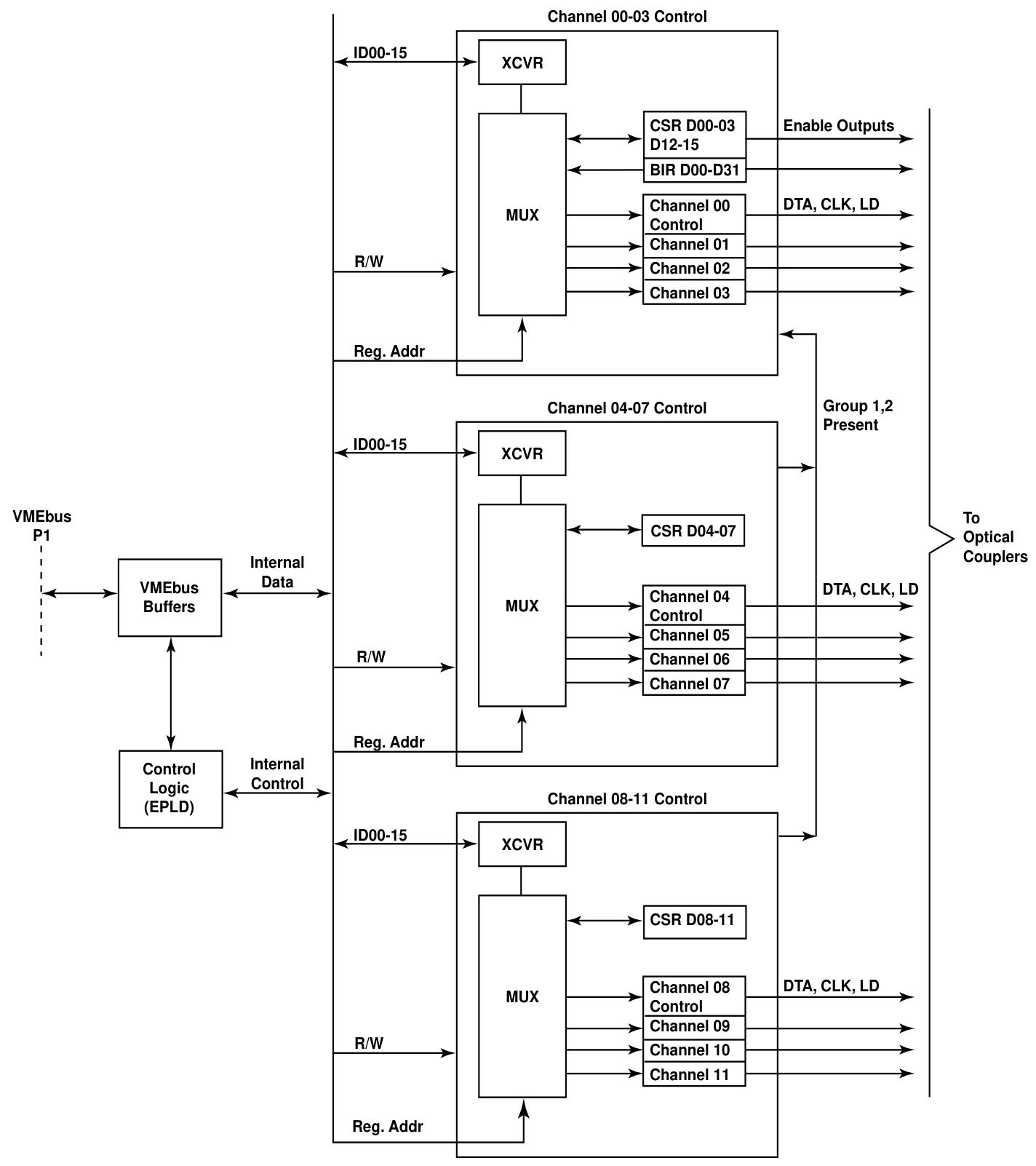
Composed of VMEbus interface, channel control, isolated analog output, and DC/DC power converter.
VMEbus interface: Communication with VMEbus is controlled by a single electrically programmable logic device (EPLD). Data and control registers are distributed in three channels to control the EPLD, respond to bus data transmission requests and control data flow, and generate data transmission acknowledgement (DTACK *) after completion of transmission.
Channel control: The data transmission control of the output D/A converter is divided into three identical 4-channel groups, each group is allocated and controlled by an EPLD, supporting optional configurations of 4, 8, or 12 channels. Each channel control EPLD contains four data registers, which receive channel data words from VMEbus and provide independent data serializers for each channel.
analog output channel
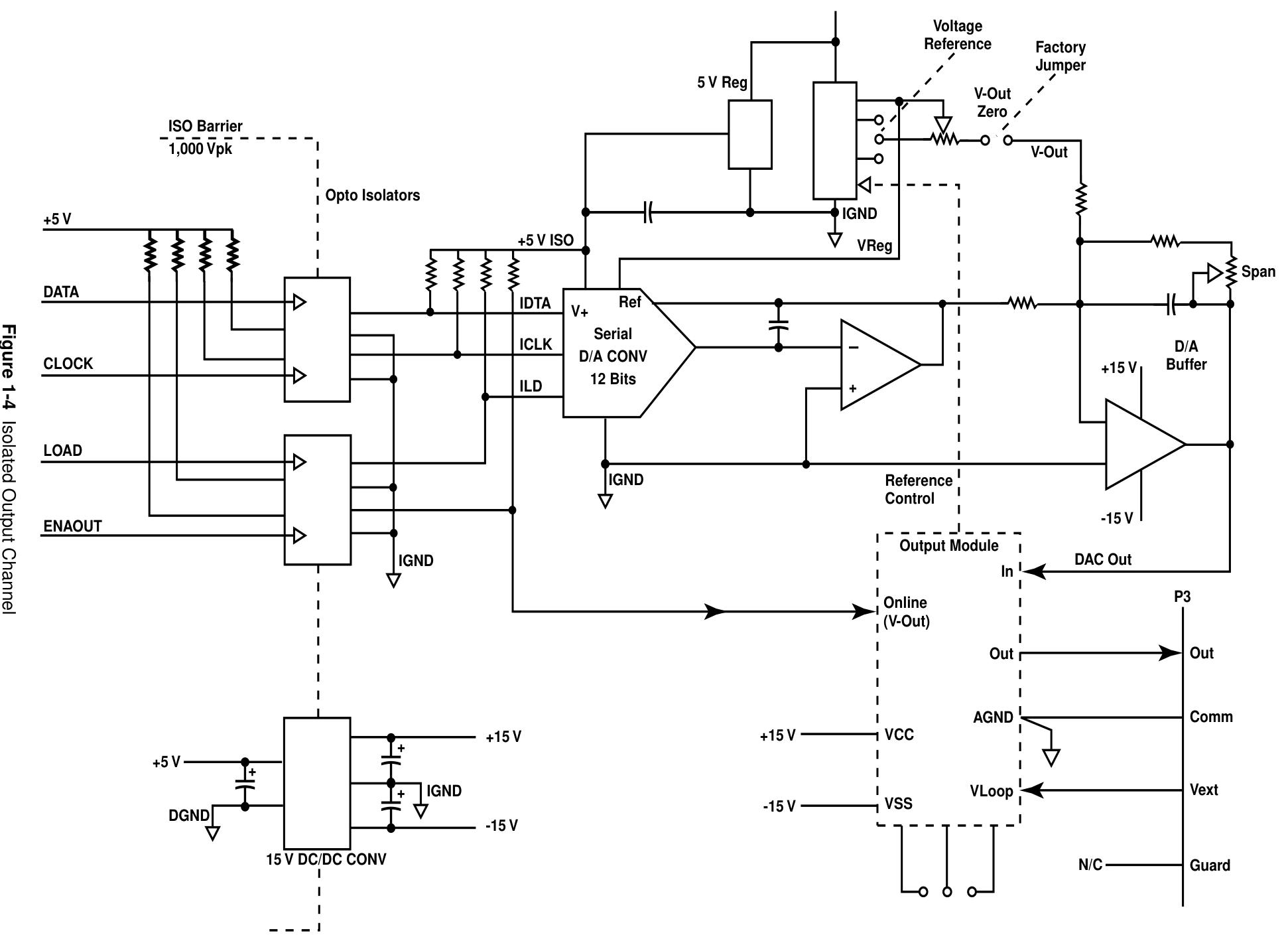
Isolation: Each output channel is isolated from VMEbus and all other channels through an isolated DC/DC converter and four optocouplers. The DC/DC converter provides ± 15 VDC isolated power supply, while the optocouplers isolate digital control signals.
Digital to Analog Conversion: A serial digital to analog (D/A) converter receives a 12 bit data word and generates a specific range of output voltage. The output module converts it to a specified voltage or current output according to the configuration.
Voltage and current output: All outputs are factory configured as unipolar voltage, bipolar voltage, or constant current. The voltage output module includes a unity gain buffer and an output switch, while the current output module includes a voltage current converter and a transmission transistor.
DC/DC power converter: Each channel contains a DC/DC converter that obtains isolated ± 15 VDC power from the VMEbus+5 VDC power bus to supply power to the isolated portion of the channel.
Configuration and Installation
Unboxing process
Some components are sensitive to electrostatic discharge, and unused boards should be stored in their original packaging. When placed on the workbench, it is recommended to insert conductive materials underneath. After receiving the goods, it is necessary to check whether there is any transportation damage. If there is, a claim should be made to the carrier and VMIC should be notified. When installing or removing the board, power off and insert the board correctly into the chassis slot.
run setup
The board address and I/O access mode are controlled by replaceable jumpers on the board, including address modifier jumpers (E15), base address selection jumpers (E13, E14, E16), and output range selection jumpers. Different jumper configurations correspond to different functions and parameters.
Bipolar voltage output: It can be configured as 2.5 V, 5 V, or 10 V through user installed jumpers, and different channels correspond to different jumpers and adjustable potentiometers.
Unipolar voltage output: configurable for 0 to 2.5 V, 0 to 5 V, or 0 to 10 V, with corresponding jumpers and adjustment components.
Current loop output: Each channel has jumper wires that can be configured with internal or external power supply, supporting different current ranges.
calibration
Before leaving the factory, it has been fully calibrated. If recalibration is required, digital multimeters, card cages, expansion cards, resistors, and other equipment need to be prepared to calibrate the bipolar voltage output, unipolar voltage output, and current output according to specific steps. After calibration, appropriate sealing agents need to be used to re seal and adjust the components.
I/O cable and front-end panel connector configuration
The front-end input connectors (P3 and P4) are standard ultra small 37 pin female D-shaped connectors with specific pin layouts and assignments, corresponding to different outputs and functions.
- OMRON
- ABB
- General Electric
- EMERSON
- Honeywell
- HIMA
- ALSTOM
- Rolls-Royce
- MOTOROLA
- Rockwell
- Siemens
- Woodward
- YOKOGAWA
- FOXBORO
- KOLLMORGEN
- MOOG
- KB
- YAMAHA
- BENDER
- TEKTRONIX
- Westinghouse
- AMAT
- AB
- XYCOM
- Yaskawa
- B&R
- Schneider
- KONGSBERG
- NI
- WATLOW
- ProSoft
- SEW
- ADVANCED
- Reliance
- TRICONEX
- METSO
- MAN
- Advantest
- STUDER
- DANAHER MOTION
- Bently
- Galil
- EATON
- MOLEX
- DEIF
- B&W
- ZYGO
- Aerotech
- DANFOSS
- Beijer
- Moxa
- Rexroth
- Johnson
- WAGO
- TOSHIBA
- BMCM
- SMC
- HITACHI
- HIRSCHMANN
- Application field
- XP POWER
- CTI
- TRICON
- STOBER
- Thinklogical
- Horner Automation
- Meggitt
- Fanuc
- Baldor
- SHINKAWA
- Other Brands
- UniOP
- KUKA
- Iba
- Beckhoff
-
 Basler 9 1606 00 101 Voltage Regulator
 -
 Basler CBS-377 Current Boost System 9109600102
 -
 Basler 8650C72 Exciter Control Module PCB Rev 5
 -
 Basler C2EE1PA0N1F BE1-32R Reverse Power Relay
 -
 Basler XR2002F Voltage Regulator 9139400101
 -
Basler 2D80367G23 DXCB De-Excitation Module 1200V 5000A
-
 Basler SR4A-2B15B3A Static Regulator 120V 50/60Hz
 -
 Basler SSR 125-12NF Static Regulator 9 1859 00 106
 -
 Basler BE1-BPR Breaker Protection Relay 9272000315
 -
 Basler SSR 63-12 Static Regulator 9 1859 00 101
 -
 Basler AEM-2020 Analog Expansion Module
 -
 Basler BE 25231-001 Transformer BE25231001
 -
 Basler MVC 108 Manual Voltage Control 9037000102
 -
 Basler PSS-100-Y5 Power System Stabilizer 0.1-5.0Hz
 -
 Basler Electric BE1A-25-M1G-A6T-N4V1F Sync-Check Relay
 -
 Basler Electric SR8A2B10B1A Static Voltage Regulator
 -
Basler Electric SR8A2B10B1A Static Voltage Regulator
-
Basler Electric SSR 125-12 Static Voltage Regulator 9185900102
-
 Basler Electric 90-73900-102 Power Supply (Westinghouse 2374A07G03)
 -
 Basler Electric 9400200117 Control Power Unit 12/24VDC 20W
 -
Basler Electric BE1-87G Solid State Generator Differential Relay
-
 Basler Electric BE1-32R Style C3ED1TA0S1F Solid State Protective Relay
 -
Basler Electric SR32A2B05B3E Static Voltage Regulator
-
 Basler Electric SR8A2B06B3A Static Voltage Regulator
 -
Basler MOC3502 90-72300-116 Motor Potentiometer
-
 Basler SR4A2310B1A Static Voltage Regulator
 -
 Basler Electric 90-88800-102 PRS-250 Veri-Sync Relay
 -
Basler Electric 90-88800-102 PRS-250 Veri-Sync Relay
-
Basler SR4A-2B05A3E Static Regulator SR4A2B05A3E
-
 Basler 9-0723-00-130 9072300130 Control Module
 -
 Basler BE1-79MA10A6JC0L0F Reclosing Relay
 -
 Basler CBS-377 Current Boost System 91096001
 -
Basler SR4A1B05A3A Static Regulator 480V 62.5V 10VA
-
 Basler BE159N A7ED1JC0S0F Protective Relay BE159N-0
 -
 Basler BE3-25A Auto-Synchronizer S.No. 728
 -
 Basler BE1-50 Instantaneous Overcurrent Relay G4EA1RG0N0F
 -
 Basler Electric KT3B Voltage Regulator
 -
 Basler Electric ACA2500-14GCSYM GigE Camera
 -
 Basler Electric XR2002F Voltage Regulator
 -
 Basler Electric BE1-50 Instantaneous Overcurrent Relay F2EA1PA0N5F
 -
 Basler Electric CBS 212A Current Boost System
 -
Basler Electric BE147NE3FE1PC3N3F Negative Sequence Voltage Relay
-
Basler Electric BE1-79MA10A6JC0L0F Automatic Reclosing Relay
-
Basler Electric BE1-59N A6E E1C B0N1F Neutral Overvoltage Relay
-
 Basler Electric MVC 108 Manual Voltage Control
 -
 Basler Electric BE1-59-A4E-E1C-A0N0F Overvoltage Relay
 -
Basler BE1-57/27R Solid State Protective Relay
-
 Basler BE3-25AX Time Overcurrent Relay
 -
BASLER ELECTRIC BE1-24/A1EF1JC1N0F / BE124A1EF1JC1N0F Overvoltage Relay
-
Basler Electric Solid State Protective Relay BE1-32R Style B2ED1PB0N0F
-
Basler BE3-51-3E1E1 9320000110 24VDC Overcurrent Relay
-
 Basler UFOV 260A Underfrequency Overvoltage Module
 -
 Basler 50F4EA1PA0N0F Instantaneous Overcurrent Relay
 -
Basler BE1-50 Instantaneous Overcurrent Relay
-
 Basler BE1-32 Solid State Protective Relay
 -
Basler SCP 250-G-60 VAR Power Factor Controller
-
Basler BE1-59N A5EE1KC0N0F Ground Fault Relay
-
Basler BE1-79A Reclosing Relay
-
Basler BE1-32R E1EA1OA0N0F Reverse Power Relay
-
 Basler DCQA-103 DCQC104-1 CMX-7D Circuit Board
 -
 Basler SSR125-12 Static Regulator 918500102
 -
Basler 90 17709 112 Regulator Control Board
-
 Basler AVC63-4 AVC634 Voltage Regulator
 -
 Basler 9 1049 04 100 PC Board Control Module
 -
Basler SR4A-2B03B3A Static Voltage Regulator
-
 Basler SR8A-2B15B3A Static Voltage Regulator
 -
 Basler KR7FFX Static Regulator 840V
 -
 Basler EL200-7 Voltage Regulator 90-660VAC 7A
 -
 Basler PRP210-1 Reverse Power Relay 9056300102
 -
 Basler SSR 63-12 Static Regulator 600VAC
 -
 Basler 9289901106 Digital Board
 -
Basler DECS100 Voltage Regulator DECS100A01
-
Basler Electric CEM-2020 Contact Expansion Module
-
Basler Electric BE3-25-1 C1 N4 Synchronizing Check Relay
-
Basler Electric ACA2000-50GM GigE Camera 2MP 50fps
-
 Basler Electric ACA2240-20GMSYM GigE Camera Sony IMX264
 -
Basler BE1-50G Ground Overcurrent Relay
-
Basler PRS250 Veri-Sync Relay
-
Basler MOC2199 Output Module
-
 Basler UFOV 260A Underfrequency Overvoltage Module
 -
 Basler BE-15482-001 Control Module
 -
Basler LSP4-7 Protective Relay
-
 Basler SCP 250-G-60 VAR Power Factor Controller
 -
Basler BE146N Negative Sequence Overcurrent Relay
-
Basler APR63-5 Automatic Voltage Regulator
-
Basler 9507900107 SR8A Retrofit Voltage Regulator
-
Basler BE1-320 Directional Power Relay
-
 Basler KR7F Voltage Regulator 9116200100
 -
Basler UFOV 260A Overvoltage Protective Module
-
 Basler AEC63-7 Analog Excitation Controller
 -
Basler 9992D90G01 Control Module
-
Basler 6966D22G01 Control Board
-
Basler 6965D40G01 Control Board
-
 Basler BE1-50/51M-104 Overcurrent Relay
 -
Basler BE1-BPR Programmable Breaker Relay
-
BASLER Electric SSR 125-9 1256 00 102 Static Voltage Regulator
-
Basler Electric MVC 112 Manual Voltage Control
-
 Basler Electric 9321000102 Control Module
 -
 Basler Electric RA-70-MDCT7 Rectifier Assembly
 -
 Basler Electric ACA1300-60GM GigE Camera
 -
 Basler Electric 6427C85G01 Interface Board
 -
Basler Electric 6965D05G01 Control Board
-
Basler Electric ACA2500-14UC Current Transducer
-
Basler Electric 9170206111 Protective Relay
-
Basler Electric BE1-11-G6D1M1J1P0E000 Protection Relay
-
Basler Electric BE1-50/51B-107 Overcurrent Relay
-
 Basler 9121000106 Voltage Controller
 -
 Basler B3E-E1P-A0N0F Solid State Protective Relay
 -
 Basler 9121000106 Manual Voltage Control
 -
Basler PRP320 Motor Pull-out Relay
-
 Basler SSE-N 250-9KW Shunt Exciter Regulator
 -
 Basler BE1-50-51B-107 Overcurrent Relay
 -
 BASLER ELECTRIC MVC 108 MANUAL VOLTAGE CONTROL MODULE 9 0370 00 102
 -
Basler BE1-59N-A7E-D1J-D0N0F Ground Overvoltage Relay
-
Basler BE1-46N-G1E-B8P-B0N0F Negative Sequence Overcurrent Relay
-
Basler BE1-951 Overcurrent Protection System
-
 Basler Electric MOC2199 Motor Operated Potentiometer
 -
Basler Electric BE1-60 Voltage Balance Solid State Relay B1FA1C1M1F
-
Basler Electric BE1-67N Directional Overcurrent Relay
-
Basler Electric PIA2400-17GM Interface Module
-
 Basler Electric V6RAB Rectifier Module
 -
Basler Electric BE1-32R Reverse Power Relay B2E E1R A0N1F
-
Basler Electric IFM-150 Firing Circuit Chassis 120V AC
-
 Basler Electric IFM-102 Firing Circuit Chassis 120V AC
 -
 Basler Electric 9170206111 NSNP Control Module
 -
Basler Electric SSR 63-12 Static Voltage Regulator
-
 Basler UFOV 260A Overvoltage Protective Module
 -
Basler SCA1300-32GM CCD Camera Lens Enclosure


