
WAGO Rail-Mount Terminal Blocks with Screw and Stud Connection
35mm ² straight/ground/power tap changer 1.5-50 (s+st+f-st) 125A (150A) 16.1 3.2-3.7 M6 flathead screwdriver (6.5 × 1.2mm)
70mm ² straight/ground/power tap 10-95 (s+st), 10-70 (f-st) 192A (232A) 20.5 6-12 M8 T-shaped wrench (6mm)
120mm ² straight through/power tap 16-150 (s+st), 16-120 (f-st) 269A (290A) 27 12-20 M10 T-shaped wrench (6mm)
240mm ² straight/power tap 70-240 (s+st+f-st) 380A 36 10-20 M10 T-shaped wrench (8mm)
WAGO Rail-Mount Terminal Blocks with Screw and Stud Connection
Detailed explanation of the core terminal block series
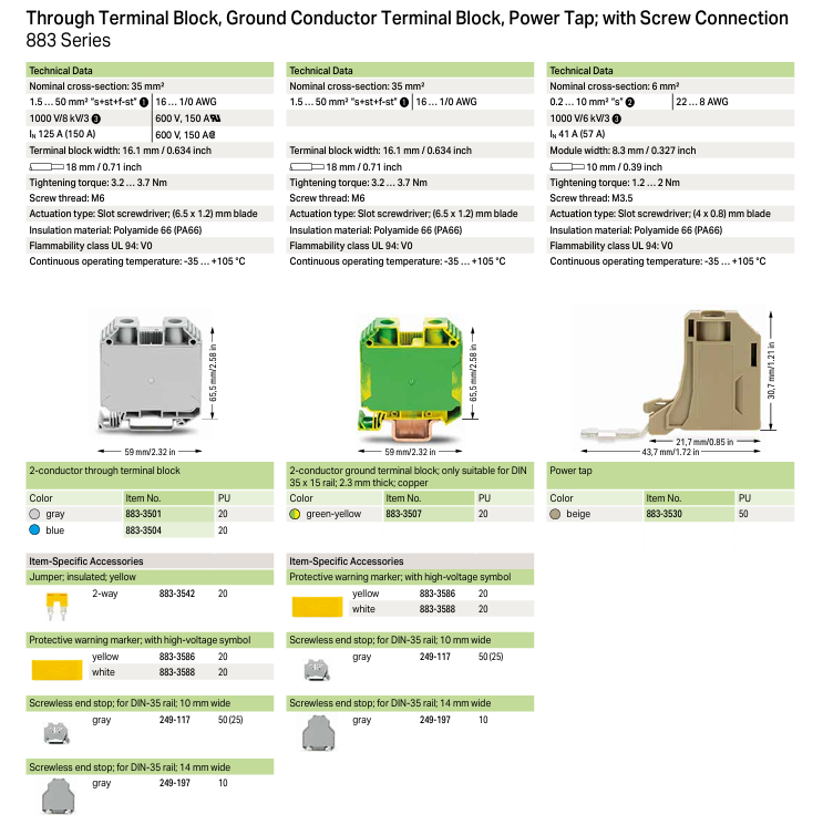
(1) 883 series (screw connected terminal block)
1. Product type and specifications
Nominal cross-sectional area Product type Suitable conductor range (mm ²) Rated current (IN) Terminal block width (mm) Tightening torque (Nm) Screw specifications Operating tool
35mm ² straight/ground/power tap changer 1.5-50 (s+st+f-st) 125A (150A) 16.1 3.2-3.7 M6 flathead screwdriver (6.5 × 1.2mm)
70mm ² straight/ground/power tap 10-95 (s+st), 10-70 (f-st) 192A (232A) 20.5 6-12 M8 T-shaped wrench (6mm)
120mm ² straight through/power tap 16-150 (s+st), 16-120 (f-st) 269A (290A) 27 12-20 M10 T-shaped wrench (6mm)
240mm ² straight/power tap 70-240 (s+st+f-st) 380A 36 10-20 M10 T-shaped wrench (8mm)
2. Key characteristics
Insulation and flame retardant: The material is Polyamide 66 (PA66), and the flame retardant rating is UL 94 V0 (35/70/120mm ²), V2 (240mm ² and 10mm ² small specifications)
Voltage parameters: rated voltage 1000V, rated impulse voltage 8kV, pollution level 3
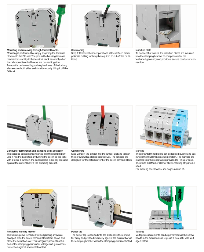
Installation method: Snap on installation on DIN rail, disassembly requires pushing back the movable buckle and tilting it; The grounding terminal block contacts the DIN rail through the grounding foot
Common connection: achieved by inserting 2/3/4 jumper wires into the jumper slot, and the jumper wires are adapted to the rated current of the terminal block
3. Typical models and packaging (PU)
Product type, color, model, packaging quantity (PU)
35mm ² straight through terminal block gray 883-3501 20
35mm ² grounding terminal block yellow green dual color 883-3507 20
70mm ² power tap beige 883-7030 10
120mm ² straight through terminal block blue 883-1204 5
240mm ² straight through terminal block gray 883-2401 5
(2) 884 series (double screw terminal block)
1. Product specifications and parameters
Nominal cross-sectional area, screw specifications, suitable conductor range (mm ²), rated current (IN), terminal block width (mm), tightening torque (Nm), operating tool
35mm ² M6 2.5-50 125A 27 3-6 open-end/plum blossom/socket wrench (10mm)
70mm ² M8 2.5-95 192A (232A) 32 6-12 open-end/plum blossom/socket wrench (13mm)
120mm ² M10 6-120 269A (290A) 42 10-20 open/plum/socket wrench (17mm)
185mm ² M12 10-185 353A 55 14-31 open-end/plum blossom/socket wrench (19mm)
300mm ² M16 25-300 520A 55 25-60 open-end/plum blossom/socket wrench (24mm)
2. Core Features
End connection capability: Each stud can connect up to 2 cable joints (back-to-back installation), and the hexagonal flange nut needs to be tightened with torque
Protective design: Can be equipped with terminal cover (beige/blue, such as 884-3580), the cover can be cut, and can be installed on both sides to prevent electric shock
Installation flexibility: snap fit on DIN rail, bottom long hole can be directly screwed onto a flat surface
3. Typical models and packaging
Nominal cross-sectional area, color, model, packaging quantity (PU), matching jumper model
35mm ² beige 884-3500 10 884-3542 (2 routes)
70mm ² beige 884-7000 10 884-7043 (3 routes)
120mm ² beige 884-1200 5 884-1242 (2 routes)
300mm ² beige 884-3000 5 884-3043 (3 routes)
(3) 885 series (single/three screw terminal block)
1. Product classification and parameters
Type: Stud specifications, nominal cross-sectional area, rated current (IN), terminal block width (mm), tightening torque (Nm), operating tool
Single bolt M6 35mm ² 125A 17.8 3-6 wrench (10mm)
Single screw M8 50mm ² 150A 22.8 6-12 wrench (13mm)
Single bolt M10 120mm ² 269A 33.8 10-20 wrench (17mm)
Single bolt M12 120mm ² 269A 33.8 10-20 wrench (19mm)
Three bolt M6 35mm ² 125A 17.8 3-6 wrench (10mm)
Three bolt M10 120mm ² 269A 33.8 10-20 wrench (17mm)
2. Core Features
Termination capability: up to 3 cable connectors (compliant with DIN 46234/46235), with anti loosening washers required
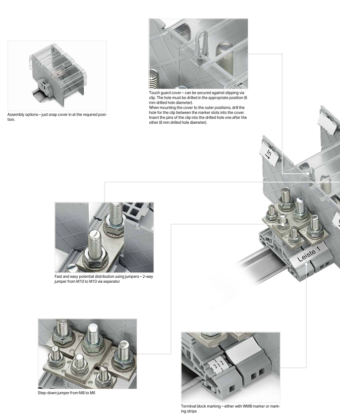
Auxiliary accessories: including partition board (with/without jumper slot), empty shell (for occupying space), 1m long transparent cover (with fixing clip)
Public connection: achieved through 2/3 jumper wires, can be equipped with variable diameter jumper wires (such as M8 to M6: 885-448)
3. Typical models and packaging
Type, Color, Model, Packaging Quantity (PU), Divider Plate Model
Single screw column (M6) gray 885-106 25 885-526
Single screw column (M10) gray 885-110 20 885-530
Three bolts (M8) gray 885-308 20 885-548
Three bolts (M10) gray 885-310 10 885-550
Accessories and supporting systems
(1) Terminal block accessories
Attachment Type Adaptation Series Model Example Specification/Characteristics Packaging Quantity (PU)
Insulated jumper 883 series 883-3542 2-channel, yellow 20
Non insulated jumper 884 series 884-7043 3-channel, compatible with M8 stud 10
High voltage warning label series 883-1286 yellow, with lightning symbol 10
Flat cable insertion board 883 series 883-7099 non insulated, compensating V-shaped structure 10
Screw free end block full series 249-117 10mm wide, gray, DIN-35 guide rail 100 (25)
(2) Marking system
Tag Type Specification Color Options Model Example Packaging Quantity (PU)
WMB card style 5mm white/yellow/red/blue/gray/orange/light green/green/purple 793-501 5 (10 strips x 10 pieces)
WMB roll pack 5-5.2mm white 2009-115 1 (1500 pieces)
Mini WSB card style 5mm and WMB card style 248-501 5 (10 pieces x 10 pieces)
Marking carrier 5mm wide gray 2009-198 200 (25)
Marking strip 11mm wide white 2009-110 1 (50m/roll)
(3) DIN rail and installation tools
1. DIN rail specifications
Material size (mm) Thickness (mm) Length (m) Rated current carrying capacity (A/m) Model Packaging quantity (PU)
Steel 35 × 15 1.5 2 125 210-114 10 (1)
Steel 35 × 15 2.3 2 125 210-118 10 (1)
Copper 35 × 15 2.3 2 309 210-198 10 (1)
2. Aluminum conductor termination tool
Contact paste: model 249-130, 20ml/tube, acid-base neutral, used for preventing oxidation after removing the oxide layer of aluminum conductors
Scraper: specialized for cleaning the oxide layer on the surface of aluminum conductors
Tightening requirements: After the initial tightening, it needs to be tightened again to the rated torque a few days later, and reconnection requires repeated processing
Technical specifications and installation requirements
1. General environmental and material requirements
Working temperature: -35...+105 ° C (full range)
Insulation material: Polyamide 66 (PA66), excellent weather resistance and mechanical strength
Flame retardant rating: UL 94 V0 (mainstream specification), V2 (small cross-sectional area such as 10mm ²)
Pollution level: Level 3 (applicable to industrial environments, with a small amount of dust but no obvious pollution)
2. Special requirements for aluminum conductor termination
Suitable conductor type: only supports round solid (RS), fan-shaped solid (SS, α=90 °, conductor grade 1) aluminum conductors
Prohibited scenario: Copper aluminum transition joints are required in humid or corrosive environments and cannot be directly connected
Operation steps: ① Scrape off the oxide layer → ② Dip in contact paste → ③ Insert the terminal block → ④ Tighten with torque → ⑤ Re tighten after a few days
3. Testing and maintenance
Voltage Test: It can be measured using a 206-707 2-pole voltage tester by operating the screw head inside the slot
Tag maintenance: Using WMB/Mini WSB system, tags can be quickly replaced and adapted to terminal block receptors
Regular inspection: Aluminum conductor connections require regular torque checks to prevent looseness
Key issue
Question 1: What are the differences in core parameters (rated current, tightening torque, operating tools) for different nominal cross-sectional areas of WAGO 883 series screw connection terminal blocks? How to choose the appropriate terminal block specifications?
Answer:
(1) Differences in core parameters of different cross-sectional areas
Nominal cross-sectional area, rated current (IN), tightening torque (Nm), screw specifications, operating tool
35mm ² 125A (150A) 3.2-3.7 M6 flathead screwdriver (6.5 × 1.2mm)
70mm ² 192A (232A) 6-12 M8 T-shaped wrench (6mm)
120mm ² 269A (290A) 12-20 M10 T-shaped wrench (6mm)
240mm ² 380A 10-20 M10 T-shaped wrench (8mm)
(2) Selection criteria
Conductor cross-sectional area: The nominal cross-sectional area of the terminal block should cover the actual range of conductor cross-sectional areas (such as a 35mm ² terminal block compatible with 1.5-50mm ² conductors);
Rated current: The terminal block IN must be greater than or equal to the maximum operating current of the circuit (e.g. 120mm ² terminal block IN=269A, suitable for a maximum 269A circuit);
Installation space: The width of the terminal block increases with the increase of cross-sectional area (35mm ² is 16.1mm, 240mm ² is 36mm), which needs to be selected based on the space of the distribution box;
Operating tools: Use a screwdriver for small cross-sectional areas (35mm ²) and a T-shaped wrench for large cross-sectional areas (70mm ² and above), matching the on-site tool conditions.
Question 2: How to achieve reliable connection between aluminum conductors and WAGO terminal blocks in humid or corrosive environments? What special operating procedures should be followed?
Answer:
(1) Connection scheme
In humid or corrosive environments, direct connection of aluminum conductors is prohibited. Copper aluminum transition joints (such as aluminum conductor crimping joints with copper connection studs) should be used. The specific adaptation is as follows:
Screw connection (883 series): After crimping the copper aluminum transition joint with the aluminum conductor, connect it according to the normal terminal connection method of the terminal block (insert the clamping unit → tighten the screw);
Screw connection (884/885 series): After crimping the copper aluminum transition ring joint with the aluminum conductor, tighten it in conjunction with the screw (with anti loosening washer).
(2) Special operating procedures
Joint selection: Transition joints must comply with DIN 46234 (uninsulated crimping joints) or DIN 46235 (covered crimping joints), with a cross-sectional area that matches the conductor;
Crimping requirements: Use specialized crimping tools to crimp according to the joint specifications, ensuring that there is no looseness or damage at the crimping point;
Sealing protection: The connection part can be additionally wrapped with waterproof tape or covered with waterproof heat shrink tubing to prevent moisture from entering;
Regular inspection: Check the connection torque and protection status every 3-6 months, and promptly address any oxidation or looseness found.
Question 3: What are the structural differences, termination capabilities, and applicable scenarios of WAGO 884 and 885 series screw terminal blocks?
Answer:
(1) Structural differences
Comparison item 884 series (double screw) 885 series (single/triple screw)
Number of bolts 2 (fixed spacing, same specifications) 1 or 3 (single bolt independent, three bolts side by side)
The width of the terminal block increases with the increase of cross-sectional area (27-55mm). The single screw column is 17.8-33.8mm, and the three screw columns are the same as the single screw column
Installation method: snap on+bottom long circular hole (flat installation) snap on (DIN rail only)
Protective accessory special cover (can be cut, single/double-sided installation) 1m long transparent cover (with fixing clip, overall protection)
(2) End connection capability
884 series: Each stud can connect up to 2 cable connectors (back-to-back installation), supporting 2.5-300mm ² conductors and compatible with DIN 46234/46235 connectors;
885 series: A single stud can connect up to 3 cable connectors, and each stud of the three studs can be independently terminated (with different cross-sectional area conductors), supporting 2.5-120mm ² conductors.
(3) Applicable scenarios
884 series: suitable for high current, multi conductor parallel scenarios (such as main circuit of distribution cabinet, industrial motor power input), requiring 2 conductors to be connected simultaneously and with high current (such as 300mm ² conductor, 520A current);
885 series: Single screw is suitable for single circuit independent connection (such as instrument signal input, small equipment power supply); Three screws are suitable for centralized layout of multiple circuits (such as power distribution of multiple branches in a control cabinet), which requires saving installation space and a small number of circuits (within 3 circuits).
- OMRON
- ABB
- General Electric
- EMERSON
- Honeywell
- HIMA
- ALSTOM
- Rolls-Royce
- MOTOROLA
- Rockwell
- Siemens
- Woodward
- YOKOGAWA
- FOXBORO
- KOLLMORGEN
- MOOG
- KB
- YAMAHA
- BENDER
- TEKTRONIX
- Westinghouse
- AMAT
- AB
- XYCOM
- Yaskawa
- B&R
- Schneider
- KONGSBERG
- NI
- WATLOW
- ProSoft
- SEW
- ADVANCED
- Reliance
- TRICONEX
- METSO
- MAN
- Advantest
- STUDER
- DANAHER MOTION
- Bently
- Galil
- EATON
- MOLEX
- DEIF
- B&W
- ZYGO
- Aerotech
- DANFOSS
- Beijer
- Moxa
- Rexroth
- Johnson
- WAGO
- TOSHIBA
- BMCM
- SMC
- HITACHI
- HIRSCHMANN
- Application field
- XP POWER
- CTI
- TRICON
- STOBER
- Thinklogical
- Horner Automation
- Meggitt
- Fanuc
- Baldor
- SHINKAWA
- Other Brands
- UniOP
- KUKA
- Iba
- Beckhoff
-
 Basler DECS-200-2L Digital Excitation Control
 -
 Basler BE1-47N Voltage Phase Sequence Relay
 -
 Basler AEC63-7 Analog Excitation Controller 220-277V
 -
 Basler BE1-50/51B-107 Overcurrent Relay
 -
 Basler Electric BE1‑32R BE1‑E1P‑BON0F Protective Relay
 -
 Basler BE1-25 Solid State Time Overcurrent Relay M1EA6PA5S1F
 -
 Basler MVC 232 Manual Voltage Control Module 90 37000 103 60VAC 55VDC
 -
 Basler RAL6144-16GM Racer GigE Line Scan Camera
 -
 Basler SSR 63-12 Static Voltage Regulator
 -
 Basler BE1-51A Overcurrent Relay
 -
 Basler BE1-87T Solid State Protective Relay
 -
 Basler SR4A2B01B3A Static Voltage Regulator
 -
 Basler SSR 32-12 Static Voltage Regulator
 -
 Basler TRR00696 Transformer 1KVA 115V
 -
 Basler DECS-100-B15 AVR Replacement
 -
Basler BE1-27 Under-Voltage Relay
-
 Basler ACA2000-50GM Interface Module
 -
 Basler AEC63-7 Analog Excitation Controller
 -
 Basler PRS 250 Veri-Sync Relay
 -
 Basler SR4A-2B15B3A Static Voltage Regulator
 -
Basler BE1-32R Power Relay
-
Basler SR8A-2B06B3E Static Voltage Regulator
-
Basler BE1-81 O/U Frequency Relay
-
 Basler BE1-51A-K2E-W6M-B1N0F Overcurrent Relay
 -
Basler BE1-851 Overcurrent Relay G3A1S1 – 48-125V AC/DC
-
 Basler BEI-51 Overcurrent Relay – NSN 5945-01-293-2363
 -
Basler Electric L301KC Protective Relay – L301KC
-
 Basler DECS-100-B15 Automatic Voltage Regulator – Generator AVR
 -
 Basler SR4A-2B15B3A Static Voltage Regulator – SR4A2B15B3A
 -
 Basler UF 312 Under Frequency Protective Module – 9094700100
 -
Basler Electric MVC 232 Manual Control Module – 60VAC 55VDC 20A
-
Basler PRS 250 Veri-Sync Relay – Generator Synchronizing Relay
-
 Basler DECS-100-A05 Digital Regulator Review
 -
 Basler AEM-2020 Analog Expansion Module Specs
 -
 Basler DECS-100-B15 Digital Excitation Specs
 -
Basler Electric 9125600106 Regulator Component
-
Basler BE1-51A-K1E-W6M-B1N0F Overcurrent Relay
-
 Basler MVC-301 MVC 300 Excitation Controller
 -
 Basler SSR 32-12 Static Voltage Regulator
 -
 Basler 9-2849-00-101 Control Module
 -
Basler BE1-51A Overcurrent Relay
-
 Basler BE1-51/27R Overcurrent Relay
 -
 Basler BE1-51 Overcurrent Relay
 -
 Basler SR8A-2B15B3A Static Voltage Regulator
 -
 Basler BE32965001 Transformer and Timer Board
 -
 Basler 9174700100 EL200-7 Excitation Limiter
 -
 Basler BE2000E AVR Voltage Regulator
 -
Basler BE1-87G Differential Relay
-
 Basler BE21834001 Generator Control Module
 -
Basler DECS-100-B15 AVR
-
 Basler D90 96801 100 PCB Card
 -
 Basler XR2002F Voltage Regulator (110 VAC, 48-480 Hz)
 -
 Basler SR8A-2B14B3A Regulator
 -
 Basler 9561500100 Module
 -
 Basler DECS-400 BE1-11 System
 -
 Basler DECS-100-B15 Excitation Control
 -
 Basler SCP 210 Frequency Controller
 -
Basler SR4A-2B15B3A Static Voltage Regulator
-
Basler BE1-32R Power Relay
-
 Basler PIA2400-17GM Power Interface Adapter
 -
 Basler MVC 232 Manual Voltage Control Module
 -
 Basler SSR 32-12 Static Voltage Regulator
 -
Basler 5MW AVR Generator Voltage Regulator
-
 Basler VR63-4B Voltage Regulator
 -
Basler DECS-100-A05 AVR for Engine Generator
-
Basler DECS-100-B15 Automatic Voltage Regulator
-
Basler BE1-32R Directional Power Relay
-
Basler BE1-87B Differential Relay
-
 Basler UFOV 260A Protective Module
 -
 Basler 9-2614-02-100 PCB Rev M
 -
Basler DECS-100-B15 Digital AVR
-
 Basler 9284900103 PS DECS-400N
 -
 Basler D4N3H1U Intertie Protection
 -
 Basler DECS-100-B15 A15 AVR
 -
 Basler KR4F Voltage Regulator
 -
 Basler BE26434 T14 Transformer
 -
 Basler SR8A-2B15B3A Regulator
 -
 Westinghouse 774B472A12 AR Relay
 -
Basler DECS-100-B15 AVR
-
Basler XR2002F Regulator 110V
-
Basler SR125-E Static Regulator
-
Basler SSR 125-12 Regulator
-
Basler MOC2599 Motor Pot
-
 Basler BE1-DFPR Feeder Relay
 -
 Basler CBS 305 Current Boost
 -
Basler BE1-25 AutoSync
-
Basler MVC 300 Voltage Control
-
 Basler BE3-25A AutoSync
 -
 Basler KR7FF Static Regulator
 -
Basler 90-49000-100 Regulator
-
 Basler 880 kVA Dry Type Transformer Specs
 -
Basler Electric BE1-25 Sync-Check Relay Specs
-
 Basler SSR 125-12 Voltage Regulator Specs
 -
 Basler Electric BE1-851 Overcurrent Relay Review
 -
Basler Electric 149D930G02 Control Sub-Assembly
-
 Basler Electric BE1-81O/UT Frequency Relay Specs
 -
 Basler Electric BE1-51/27C Overcurrent Relay
 -
 Basler Electric 149D956G02 Industrial Component
 -
Basler Electric BE1-51A Overcurrent Relay Specs
-
 Basler Electric BE1-40Q Loss of Excitation Relay
 -
Basler DECS-200 Excitation Control System
-
 Basler DECS-200 Voltage Regulator 56-277V AC / 125V DC
 -
Basler BE1-87T Transformer Differential Relay
-
 Basler RDP-110-S1 Protection Relay
 -
 Basler BE1-700V Digital Protective Relay
 -
 Basler BE1-951 Overcurrent Protection System
 -
 Basler DECS-300 Digital Excitation Control
 -
 Basler DECS-200 Digital Excitation Control
 -
 Basler DECS-200-1C Excitation Control System
 -
Basler DECS-200-1L Digital Excitation Control
-
 Basler Electric BE1-GPS Generator Protection System
 -
Basler Electric DECS-200-1C Digital Excitation Controller
-
 Basler Electric DECS125-15 Excitation Control with Power Module
 -
Basler Electric BE1-87G Differential Relay
-
 Basler Electric BE1-11 Protection System I5A3M2P2N0EA00
 -
Basler Electric DECS-200-1C Excitation Control System
-
Basler Electric BE1-11g Generator Protection Relay
-
Basler Electric DECS 125-15-B2C1 V2.0.9 Excitation Control
-
Basler Electric BE1-81O/UT3ED1JA7N2F Frequency Relay
-
Basler Electric BE1-81O/UT3EE1YB7N1F Frequency Relay
-
 Basler Electric DECS-200-1L Digital Excitation Control System
 -
Basler DECS125-15-B2C1 Excitation Control
-
 Basler 9507900205 SSR Retrofit Voltage Regulator
 -
 Basler BE2000E Digital Voltage Regulator
 -
 Basler BE1-GPS Generator Protection System
 -
Basler DECS-250-CN1CN1N Digital Excitation Control
-
 Basler DGC-2020 Genset Controller
 -
Basler BE1-81O UT3ED1LA7N0F Frequency Relay (Variant)


