
Westinghouse WGen7500DF Dual Fuel Portable Generator
Peak power gasoline: 9500W; propane: 8550W meets the instantaneous high power demand of motor equipment during startup
Engine 420cc OHV four stroke, 3600rpm single cylinder design, high combustion efficiency, strong stability
Westinghouse WGen7500DF Dual Fuel Portable Generator
Core parameters and product configuration
1. Key specifications
Specific parameter notes for specification items
Operating power gasoline: 7500W; propane: 6750W. Propane power is slightly lower, suitable for different fuel needs
Peak power gasoline: 9500W; propane: 8550W meets the instantaneous high power demand of motor equipment during startup
Engine 420cc OHV four stroke, 3600rpm single cylinder design, high combustion efficiency, strong stability
The fuel related gasoline tank has a capacity of 25L (6.6 gallons) and is compatible with unleaded gasoline grades 87-93 (ethanol ≤ 10%); Support standard propane tanks with OPD valves to disable E15/E85 ethanol gasoline to avoid fuel system damage
Oil specification capacity 1.1L (1.16 quarts), recommended SAE 10W-30 extreme temperature can choose 5W-30 or 10W-40 synthetic oil
Starting methods include manual start, electric start, and remote start (up to 30 meters away). Remote control needs to be paired first, and the battery model is CR2016 (2 cells)
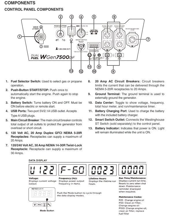
Output interface: 120V 20A dual hole GFCI socket x 2, 120/240V 30A locked socket x 1, 5V/2.1A USB interface x 2, total load not exceeding 40A, supporting multiple devices to be powered simultaneously
Other spark plug models F7TC (with a gap of 0.024-0.032 inches), with a net weight of approximately 59kg, and the noise level is not clearly marked as meeting EPA, CARB, CSA certification standards
2. Core configuration
Fuel switching: The control panel is equipped with a fuel selection switch, which supports switching during operation (propane tank needs to be connected in advance).
Safety configuration: low oil automatic shutdown, overload protection circuit breaker, GFCI leakage protection, neutral wire and frame grounding binding, spark suppressor (fireproof star ignition).
Convenient configuration: digital display screen (displaying voltage, frequency, operating hours, maintenance reminders), foldable handle+swivel wheel (easy to move), battery charging port (including matching charger).
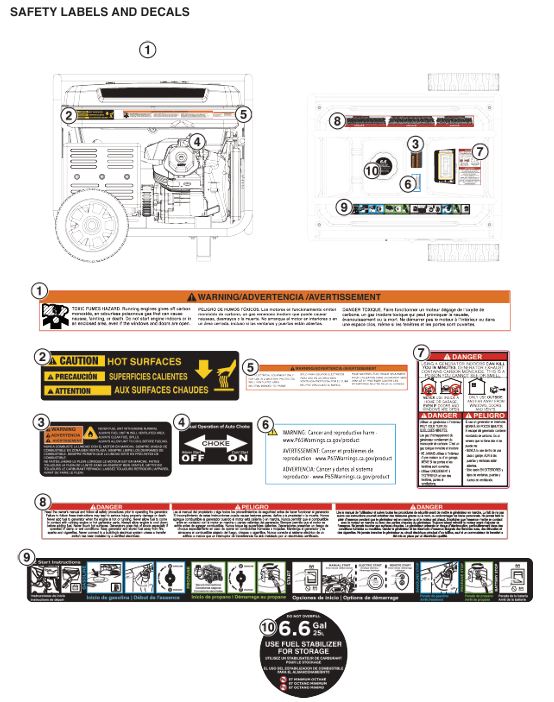
Safety operation standards
1. Environment and placement safety
Placement requirements: Use only in outdoor ventilated areas, at least 5 feet (1.5 meters) away from doors, windows, and ventilation openings; Place on a hard horizontal surface to avoid tilting and causing fuel/oil leakage.
Environmental restrictions: It is prohibited to operate in enclosed spaces (garages, basements, etc.) (exhaust containing carbon monoxide); Do not use in damp, rainy or snowy weather or near water sources (to prevent electric shock); The operating range of ambient temperature is 5 ° F (-15 ° C) -122 ° F (50 ° C). After storage, it needs to be restored to this range before restarting.
2. Fuel and Electricity Safety
Fuel operation:
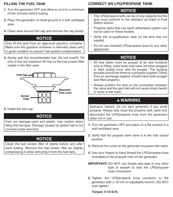
Turn off the engine and cool it down for 2 minutes before refueling. Do not smoke or approach open flames; The fuel tank cannot be filled to its full capacity, leaving room for expansion. Any spilled fuel must be wiped dry and allowed to evaporate before starting.
The propane tank should be placed upright on the ground, away from heat sources and generator exhaust ports; After connecting, use soapy water to check if the interface is leaking (if there is bubbling, it is a leak). Do not start until the leak is eliminated.
Electricity operation:
It is prohibited to directly connect to the household power distribution system, and it must be connected through a qualified electrician installed conversion switch (to avoid reverse power transmission to the grid).
Only use grounded three core extension cables, with wire diameter matching the load and length (12 cable for 20A load ≤ 50 feet, 10 cable for ≤ 100 feet); Do not use damaged or aged cables.
Disconnect all loads before starting, and connect them in sequence after stable operation (first high-power equipment, then low-power equipment), with the total load not exceeding the rated power.
3. Personnel safety
Wear goggles and gloves during operation, curl up long hair, and avoid contact with high-temperature components such as exhaust pipes (which are prone to burns).
Do not operate after fatigue, drinking alcohol, or taking medication. Children and pets should stay away from running generators (at least 3 meters away).
If symptoms such as dizziness and nausea occur after inhaling carbon monoxide, immediately transfer to fresh air and seek medical attention if severe.
Operation process (assembly+start+stop)
1. Assembly and preparation
Installing wheels and handles: Fix the wheels to the frame with axle pins and split pins, and install and lock the handles with buckles.
Add engine oil: Place the generator horizontally, unscrew the oil filler cap, add the recommended model of engine oil to between the "L" and "H" marks on the dipstick, and tighten the dipstick.
Fuel preparation:
Gasoline: Open the fuel tank cap, add qualified gasoline, tighten the fuel tank cap, and clean any spilled fuel.
Propane: Connect one end of the matching hose to the propane inlet of the generator (manually tighten, no sealing tape required), and the other end to the propane tank valve. After opening the tank valve, check for leaks with soapy water.
Battery connection: Connect the battery quick connector to ensure a secure connection (both electric and remote start rely on the battery).
2. Start the process
Preprocessing: Turn the battery switch to "ON", the fuel selection switch to the corresponding fuel position (gasoline/propane), turn off all loads, and remote start requires pairing to be completed first (long press the pairing button on the control panel, then press the start stop button on the remote control).
Start operation:
Electric start: Press and hold the "START" button on the control panel for 2 seconds, then release it after the engine starts.
Remote control start: Press the "START" button on the remote control for 1 second, effective up to 30 meters away.
Hand pulled start: The refrigerator needs to close the air door, hold the starting rope and slowly pull it until there is resistance, then quickly pull it; After starting, gradually open the air door to the "RUN" position.
Stable operation: Run without load for 3-5 minutes to preheat, observe that the display screen parameters are normal (voltage and frequency are stable), and connect to the load after there is no abnormal noise.
3. Shutdown process
Normal shutdown: Disconnect all loads, let the generator run without load for 3-5 minutes, press the "STOP" button on the control panel or remote control, close the fuel valve (gasoline: close the tank valve; propane: close the tank valve), and finally close the battery switch.
Emergency shutdown: In case of leakage, abnormal noise, overload, etc., press the "STOP" button directly or turn off the engine switch to forcibly shut down.
Cleaning and tidying up: Disconnect fuel and power connections, clean equipment surfaces, and store hoses and cables.
Maintenance and Storage
1. Routine maintenance
Maintenance project cycle operation content
Check the oil level before each use, and if it is below the "L" mark, replenish it
Oil change for the first 25 hours/every 50 hours thereafter. After heating up, drain the oil, replace with new oil, and drain the bolt seal gasket
Air filter maintenance Check every 25 hours/Clean every 50 hours/Replace the foam filter element every 300 hours Clean it with detergent, dry it in the air and apply a small amount of engine oil; Paper filter element is blown with compressed air
Spark plug maintenance check every 100 hours/replace every 300 hours to clean carbon deposits, check gap (0.024-0.032 inches), replace if damaged
Clean the spark suppressor every 100 hours by removing the muffler cover, cleaning the carbon buildup on the filter screen, and replacing it if it is damaged
Replace the fuel filter every 100 hours, close the fuel valve, remove the old filter element, and install the new filter element in the original direction
When the battery is not used for a long time, it should be charged monthly with a matching charger to maintain sufficient power and avoid damage caused by power loss
2. Storage requirements
Short term storage (≤ 1 month): Clean the equipment, empty the residual fuel in the hose, close the fuel valve, and store in a dry and ventilated place.
Mid term storage (2-6 months): Add fresh fuel and stabilizer, empty the fuel in the carburetor float, disconnect the battery and charge it monthly.
Long term storage (>6 months):
Drain the fuel tank and carburetor, and replace with new engine oil.
Remove the spark plug, inject 1 teaspoon of engine oil into the cylinder, pull the starting rope several times (to prevent corrosion), and reinstall the spark plug.
Disconnect the battery, store it separately after fully charging, cover the generator with a dust cover, and place it in a dry and cool place.
Winter storage: After following the long-term storage process, inject RV specific antifreeze (177mL) into the water pump to prevent freezing and cracking.
Common troubleshooting
Possible causes and solutions for the fault phenomenon
Unable to start battery depletion, fuel shortage/deterioration, spark plug failure, propane leakage, incorrect throttle position for charging or battery replacement; Supplement fresh fuel; Clean/replace spark plugs; Check for propane leaks; Cold engine closes the air door, hot engine opens the air door
Immediately stop the machine after starting, low oil protection triggered, load not disconnected, fuel supply interrupted to replenish oil; Disconnect all loads; Check if the fuel valve is open and if the hose is blocked
Insufficient power/unstable speed, excessive load, clogged air filter, poor fuel supply, unadjusted high altitude, reduced load to rated range; Clean/replace the air filter; Check the fuel filter and hoses; High altitude kits need to be installed for altitudes greater than 5000 feet
No output voltage circuit breaker tripped, GFCI not reset, loose wiring, load short circuit, reset circuit breaker after overload investigation; Press the "RESET" button on the GFCI socket; Tighten the wiring; Troubleshooting equipment short circuit issues
Abnormal operation of propane mode, hose bending, fuel selection switch not in place, carburetor residual gasoline sorting hose to avoid bending; Turn the fuel switch to full position; Switch to gasoline mode, exhaust residual gasoline, and then switch back to propane
- OMRON
- ABB
- General Electric
- EMERSON
- Honeywell
- HIMA
- ALSTOM
- Rolls-Royce
- MOTOROLA
- Rockwell
- Siemens
- Woodward
- YOKOGAWA
- FOXBORO
- KOLLMORGEN
- MOOG
- KB
- YAMAHA
- BENDER
- TEKTRONIX
- Westinghouse
- AMAT
- AB
- XYCOM
- Yaskawa
- B&R
- Schneider
- KONGSBERG
- NI
- WATLOW
- ProSoft
- SEW
- ADVANCED
- Reliance
- TRICONEX
- METSO
- MAN
- Advantest
- STUDER
- DANAHER MOTION
- Bently
- Galil
- EATON
- MOLEX
- DEIF
- B&W
- ZYGO
- Aerotech
- DANFOSS
- Beijer
- Moxa
- Rexroth
- Johnson
- WAGO
- TOSHIBA
- BMCM
- SMC
- HITACHI
- HIRSCHMANN
- Application field
- XP POWER
- CTI
- TRICON
- STOBER
- Thinklogical
- Horner Automation
- Meggitt
- Fanuc
- Baldor
- SHINKAWA
- Other Brands
- UniOP
- KUKA
- Iba
- Beckhoff
-
 Basler D90 96801 100 PCB Card
 -
 Basler XR2002F Voltage Regulator (110 VAC, 48-480 Hz)
 -
 Basler SR8A-2B14B3A Regulator
 -
 Basler 9561500100 Module
 -
 Basler DECS-400 BE1-11 System
 -
 Basler DECS-100-B15 Excitation Control
 -
 Basler SCP 210 Frequency Controller
 -
 Basler SR4A-2B15B3A Static Voltage Regulator
 -
 Basler BE1-32R Power Relay
 -
 Basler PIA2400-17GM Power Interface Adapter
 -
 Basler MVC 232 Manual Voltage Control Module
 -
 Basler SSR 32-12 Static Voltage Regulator
 -
 Basler 5MW AVR Generator Voltage Regulator
 -
 Basler VR63-4B Voltage Regulator
 -
 Basler DECS-100-A05 AVR for Engine Generator
 -
 Basler DECS-100-B15 Automatic Voltage Regulator
 -
 Basler BE1-32R Directional Power Relay
 -
 Basler BE1-87B Differential Relay
 -
 Basler UFOV 260A Protective Module
 -
 Basler 9-2614-02-100 PCB Rev M
 -
Basler DECS-100-B15 Digital AVR
-
 Basler 9284900103 PS DECS-400N
 -
 Basler D4N3H1U Intertie Protection
 -
 Basler DECS-100-B15 A15 AVR
 -
 Basler KR4F Voltage Regulator
 -
 Basler BE26434 T14 Transformer
 -
 Basler SR8A-2B15B3A Regulator
 -
 Westinghouse 774B472A12 AR Relay
 -
Basler DECS-100-B15 AVR
-
Basler XR2002F Regulator 110V
-
Basler SR125-E Static Regulator
-
 Basler SSR 125-12 Regulator
 -
 Basler MOC2599 Motor Pot
 -
 Basler BE1-DFPR Feeder Relay
 -
 Basler CBS 305 Current Boost
 -
 Basler BE1-25 AutoSync
 -
 Basler MVC 300 Voltage Control
 -
 Basler BE3-25A AutoSync
 -
 Basler KR7FF Static Regulator
 -
 Basler 90-49000-100 Regulator
 -
 Basler 880 kVA Dry Type Transformer Specs
 -
 Basler Electric BE1-25 Sync-Check Relay Specs
 -
 Basler SSR 125-12 Voltage Regulator Specs
 -
 Basler Electric BE1-851 Overcurrent Relay Review
 -
Basler Electric 149D930G02 Control Sub-Assembly
-
 Basler Electric BE1-81O/UT Frequency Relay Specs
 -
 Basler Electric BE1-51/27C Overcurrent Relay
 -
 Basler Electric 149D956G02 Industrial Component
 -
Basler Electric BE1-51A Overcurrent Relay Specs
-
 Basler Electric BE1-40Q Loss of Excitation Relay
 -
 Basler DECS-200 Excitation Control System
 -
 Basler DECS-200 Voltage Regulator 56-277V AC / 125V DC
 -
Basler BE1-87T Transformer Differential Relay
-
 Basler RDP-110-S1 Protection Relay
 -
 Basler BE1-700V Digital Protective Relay
 -
 Basler BE1-951 Overcurrent Protection System
 -
 Basler DECS-300 Digital Excitation Control
 -
 Basler DECS-200 Digital Excitation Control
 -
 Basler DECS-200-1C Excitation Control System
 -
Basler DECS-200-1L Digital Excitation Control
-
 Basler Electric BE1-GPS Generator Protection System
 -
Basler Electric DECS-200-1C Digital Excitation Controller
-
 Basler Electric DECS125-15 Excitation Control with Power Module
 -
 Basler Electric BE1-87G Differential Relay
 -
 Basler Electric BE1-11 Protection System I5A3M2P2N0EA00
 -
Basler Electric DECS-200-1C Excitation Control System
-
Basler Electric BE1-11g Generator Protection Relay
-
Basler Electric DECS 125-15-B2C1 V2.0.9 Excitation Control
-
 Basler Electric BE1-81O/UT3ED1JA7N2F Frequency Relay
 -
Basler Electric BE1-81O/UT3EE1YB7N1F Frequency Relay
-
 Basler Electric DECS-200-1L Digital Excitation Control System
 -
Basler DECS125-15-B2C1 Excitation Control
-
 Basler 9507900205 SSR Retrofit Voltage Regulator
 -
 Basler BE2000E Digital Voltage Regulator
 -
 Basler BE1-GPS Generator Protection System
 -
Basler DECS-250-CN1CN1N Digital Excitation Control
-
 Basler DGC-2020 Genset Controller
 -
 Basler BE1-81O UT3ED1LA7N0F Frequency Relay (Variant)
 -
 Basler BE1-81O UT3EE1YA9S0F Frequency Relay (Variant)
 -
Basler BE1-81O Over/Under Frequency Relay
-
Basler DECS125-15 Digital Excitation Control
-
Basler Electric BE1-951 Overcurrent Protection System
-
 Basler Electric BE1-700V Digital Protective Relay
 -
 Basler Electric APR63-5 Automatic Voltage Regulator
 -
Basler Electric BE1-851 Overcurrent Protection System
-
Basler Electric DECS-250-LN1SN1N Excitation Control
-
 Basler Electric BE1-87T Transformer Differential Relay
 -
Basler Electric DECS-200-1L Excitation Control System
-
 Basler Electric 9310300100 DECS-300 Excitation Control
 -
 Basler Electric SSE-N 125-4.5KW Shunt Exciter Regulator
 -
 Basler Electric DGC-2020HD-5NS1DNSBA Genset Controller
 -
Basler Electric BE1-81-O/UT3EE1JB7N1F Frequency Relay
-
Basler Electric BE1-81T1EE1WA0N1F Frequency Relay
-
 Basler Electric BE1-25M1EA6PN5R1F Sync-Check Relay
 -
 Basler Electric BE1-GPS Generator Protection System
 -
Basler Electric DECS-250-LN1SN1N Excitation Control Rev V
-
 Basler Electric DECS-250-CN2CN1N Excitation Control
 -
Basler Electric BE1-50/51B-207 Overcurrent Relay
-
Basler Electric DECS-300-C0N0 Excitation Control System
-
Basler Electric DECS-200 Digital Excitation Control System
-
Basler Electric DECS-250-LN1CN1N Excitation Unit
-
Basler Electric DECS-250 LN2SA1D Excitation Unit Specs
-
Basler Electric BE1-87T Transformer Relay Review
-
Basler Electric BE1-11 Protection System
-
Basler Electric BE1-GPS100-E4N1H1N Protection System
-
 Allen-Bradley 442G-MABH-R Safety Module
 -
 Beckhoff CX1030-0111 PLC Assembly Profile
 -
 FANUC IC693CPU364 PLC Module
 -
 Orange Denmark Type 200816 220 PLC Specs
 -
 OMRON C200H-SNT31 Sysmac PLC Module
 -
 Allen Bradley 20AB022A3AYNANC0 PowerFlex 70
 -
 OMRON C200HW-PCU01 Position Control Unit
 -
 ABB AO845A-eA Analog Output Module
 -
 OMRON CJ1M-CPU22 CPU Unit
 -
 Allen Bradley 100-E265ED11 Contactor
 -
 Honeywell 51304511-100 Interface Module
 -
 SOLEXY BXF3S0101N0018 Gateway Module
 -
 OMRON CJ2H-CPU65 CPU Unit
 -
 Automation Direct GS2-45P0 AC Drive
 -
 M68-2000 2-Axis Motion CNC Controller
 -
 OMRON CJ1M-CPU11 V3.0 PLC CPU Unit
 -
 OMRON CJ1W-NC413 4-Axis Positioning Controller
 -
 OMRON 3G2A3-PRO16 Programming Console HMI
 -
 Siemens 3VT8440-2AA04-2GA2 Molded Case Circuit Breaker
 -
 Siemens 3RT5045 Contactor Series
 -
 OMRON C200HS-CPU01-E SYSMAC PLC Controller
 -
 OMRON C500-NC103-E Positioning Control Unit
 -
 OMRON CJ1W-TC001 Temperature Control Unit


