
Westinghouse iGen5000 Digital Inverter Generator
Engine parameters: displacement 224cc, spark plug model 97109-F7RTC, electrode clearance 0.024-0.032 inches (0.60-0.80mm), intake valve clearance 0.0031-0.0047 inches (0.08-0.12mm), exhaust valve clearance 0.0051-0.0067 inches (0.13-0.17mm).
Westinghouse iGen5000 Digital Inverter Generator
Core parameters and configuration of the product
1. Core performance parameters
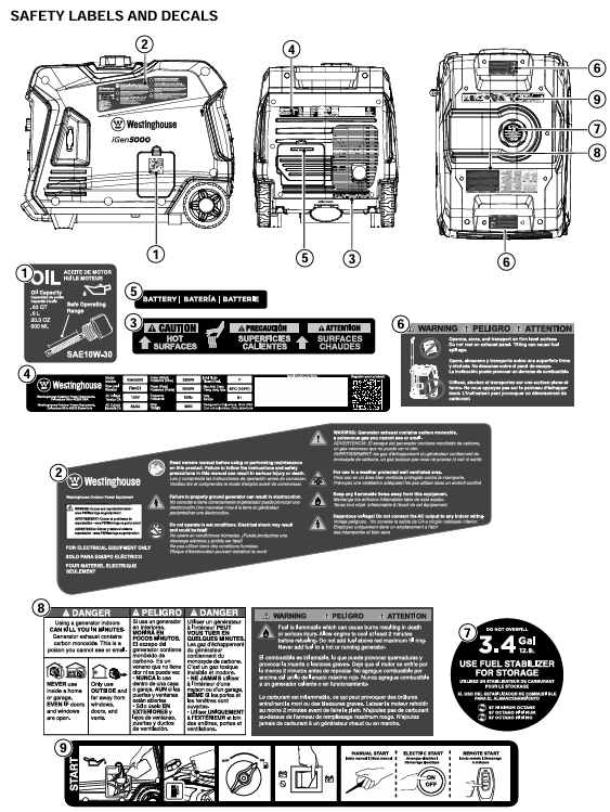
Power specifications: Operating power of 3900 watts, peak power of 5000 watts, rated voltage of 120V, rated frequency of 60Hz, total harmonic distortion ≤ 3%, single-phase output.
Engine parameters: displacement 224cc, spark plug model 97109-F7RTC, electrode clearance 0.024-0.032 inches (0.60-0.80mm), intake valve clearance 0.0031-0.0047 inches (0.08-0.12mm), exhaust valve clearance 0.0051-0.0067 inches (0.13-0.17mm).
Fuel and engine oil: Tank capacity 3.4 gallons (12.8 liters), recommended 87-93 octane gasoline, ethanol content ≤ 10% (E15/E85 prohibited); The oil capacity is 0.63 US quarts (0.60 liters), and the recommended model for regular use is 10W-30. For extreme temperatures, 5W-30, 10W-40, or 5W-30 synthetic oil can be selected.
Start and Control: Supports recoil start, electric start, remote start (up to 99 feet/30 meters), equipped with a digital data center that can display remaining operating time, power output, fuel level, voltage, and cumulative operating hours.
2. Key configurations
Control panel: including 120V 20A dual socket (NEMA 5-20R), 120V 30A socket (NEMA TT-30R), USB dual port (5V/2.1A), parallel operation interface, overload reset button, ECO mode switch, etc.
Safety configuration: low oil level indicator light, overload indicator light, output ready indicator light, main circuit breaker and branch circuit breaker, floating neutral grounding system, spark plug lightning arrester.
Portable design: equipped with a retractable handle, transport wheels, and a two person carrying handle, making it easy to move and transport.
Safety operation standards (top priority)
1. Environment and scene security
Only operate in well ventilated outdoor areas, away from closed or semi closed spaces such as doors, windows, ventilation openings, garages, basements, etc., to prevent carbon monoxide poisoning.
Maintain a ventilation gap of at least 5 feet (1.5 meters) around the generator, avoid flammable and combustible materials, and cool for at least 30 minutes after operation before storage or transportation.
Do not use in damp environments (rainy, snowy, or waterlogged), avoid skin contact with engine oil and gasoline, and wear protective equipment during operation.
2. Fuel safety operation
Before refueling, the engine must be turned off and cooled for at least 5 minutes. Smoking or being close to sources of ignition is prohibited to avoid fuel spillage.
Fuel should be stored in approved containers, in a well ventilated area, away from heat and ignition sources, and gasoline should not be used as a cleaning agent.
If there is a fuel leak, it should be wiped clean immediately, and the generator should be started only after the leak area is completely dry. Burning the leaked fuel is prohibited.
3. Electrical safety
It is prohibited to directly connect to the building's power grid unless the conversion switch is installed by a qualified electrician and complies with local electrical regulations.
Only use grounded three core extension cords, tools, and appliances, or double insulated equipment to avoid using worn or damaged wires.
When starting and shutting down the generator, it is necessary to disconnect all load connections and gradually add loads to avoid instantaneous overload.
4. Operation taboos
Not suitable for driving medical support equipment, operation is prohibited when fatigued, under the influence of alcohol, or under the influence of drugs.
During transportation or maintenance, it is necessary to disconnect the spark plug wire and battery connection to prevent accidental starting.
Avoid tilting or flipping the generator to prevent fuel or oil leakage.
Complete operational process
1. Preparation before startup
Check that the generator is placed in a horizontal, dry, and ventilated outdoor area, away from doors, windows, and flammable materials.
Confirm that the oil level is between the L (low) and H (high) marks on the dipstick. If it is insufficient, add the recommended model of oil (new engines do not have oil and need to be refilled for the first time).
Check that the fuel is sufficient, the fuel switch is in the off position, all loads have been disconnected, and the battery switch is in the off state.
Connect battery: Open the battery access cover, ensure the battery is securely fixed, connect the quick connector, and reset the battery cover.
2. Startup steps
Turn on the fuel switch (clockwise to the ON position).
Turn on the battery switch (press to the ON position).
Choose the startup method:
Backlash start: Slowly pull the recoil handle until resistance is felt, then quickly pull it.
Electric start: Long press the start/stop button on the control panel for 2 seconds.
Remote start: Long press the ON button on the remote control for 1 second (distance not exceeding 99 feet).
Maintenance Plan and Operation
1. Battery maintenance
After running for 30-60 minutes, the generator will automatically charge the battery. If not in use for a long time, the accompanying charger should be used to charge for 8 hours per month (no more than 8 hours to avoid overcharging).
- OMRON
- ABB
- General Electric
- EMERSON
- Honeywell
- HIMA
- ALSTOM
- Rolls-Royce
- MOTOROLA
- Rockwell
- Siemens
- Woodward
- YOKOGAWA
- FOXBORO
- KOLLMORGEN
- MOOG
- KB
- YAMAHA
- BENDER
- TEKTRONIX
- Westinghouse
- AMAT
- AB
- XYCOM
- Yaskawa
- B&R
- Schneider
- KONGSBERG
- NI
- WATLOW
- ProSoft
- SEW
- ADVANCED
- Reliance
- TRICONEX
- METSO
- MAN
- Advantest
- STUDER
- DANAHER MOTION
- Bently
- Galil
- EATON
- MOLEX
- DEIF
- B&W
- ZYGO
- Aerotech
- DANFOSS
- Beijer
- Moxa
- Rexroth
- Johnson
- WAGO
- TOSHIBA
- BMCM
- SMC
- HITACHI
- HIRSCHMANN
- Application field
- XP POWER
- CTI
- TRICON
- STOBER
- Thinklogical
- Horner Automation
- Meggitt
- Fanuc
- Baldor
- SHINKAWA
- Other Brands
- UniOP
- KUKA
- Iba
- Beckhoff
-
 Basler D90 96801 100 PCB Card
 -
 Basler XR2002F Voltage Regulator (110 VAC, 48-480 Hz)
 -
 Basler SR8A-2B14B3A Regulator
 -
 Basler 9561500100 Module
 -
 Basler DECS-400 BE1-11 System
 -
 Basler DECS-100-B15 Excitation Control
 -
 Basler SCP 210 Frequency Controller
 -
 Basler SR4A-2B15B3A Static Voltage Regulator
 -
 Basler BE1-32R Power Relay
 -
 Basler PIA2400-17GM Power Interface Adapter
 -
 Basler MVC 232 Manual Voltage Control Module
 -
 Basler SSR 32-12 Static Voltage Regulator
 -
 Basler 5MW AVR Generator Voltage Regulator
 -
 Basler VR63-4B Voltage Regulator
 -
 Basler DECS-100-A05 AVR for Engine Generator
 -
 Basler DECS-100-B15 Automatic Voltage Regulator
 -
 Basler BE1-32R Directional Power Relay
 -
 Basler BE1-87B Differential Relay
 -
 Basler UFOV 260A Protective Module
 -
 Basler 9-2614-02-100 PCB Rev M
 -
Basler DECS-100-B15 Digital AVR
-
 Basler 9284900103 PS DECS-400N
 -
 Basler D4N3H1U Intertie Protection
 -
 Basler DECS-100-B15 A15 AVR
 -
 Basler KR4F Voltage Regulator
 -
 Basler BE26434 T14 Transformer
 -
 Basler SR8A-2B15B3A Regulator
 -
 Westinghouse 774B472A12 AR Relay
 -
Basler DECS-100-B15 AVR
-
Basler XR2002F Regulator 110V
-
Basler SR125-E Static Regulator
-
 Basler SSR 125-12 Regulator
 -
 Basler MOC2599 Motor Pot
 -
 Basler BE1-DFPR Feeder Relay
 -
 Basler CBS 305 Current Boost
 -
 Basler BE1-25 AutoSync
 -
 Basler MVC 300 Voltage Control
 -
 Basler BE3-25A AutoSync
 -
 Basler KR7FF Static Regulator
 -
 Basler 90-49000-100 Regulator
 -
 Basler 880 kVA Dry Type Transformer Specs
 -
 Basler Electric BE1-25 Sync-Check Relay Specs
 -
 Basler SSR 125-12 Voltage Regulator Specs
 -
 Basler Electric BE1-851 Overcurrent Relay Review
 -
Basler Electric 149D930G02 Control Sub-Assembly
-
 Basler Electric BE1-81O/UT Frequency Relay Specs
 -
 Basler Electric BE1-51/27C Overcurrent Relay
 -
 Basler Electric 149D956G02 Industrial Component
 -
Basler Electric BE1-51A Overcurrent Relay Specs
-
 Basler Electric BE1-40Q Loss of Excitation Relay
 -
 Basler DECS-200 Excitation Control System
 -
 Basler DECS-200 Voltage Regulator 56-277V AC / 125V DC
 -
Basler BE1-87T Transformer Differential Relay
-
 Basler RDP-110-S1 Protection Relay
 -
 Basler BE1-700V Digital Protective Relay
 -
 Basler BE1-951 Overcurrent Protection System
 -
 Basler DECS-300 Digital Excitation Control
 -
 Basler DECS-200 Digital Excitation Control
 -
 Basler DECS-200-1C Excitation Control System
 -
Basler DECS-200-1L Digital Excitation Control
-
 Basler Electric BE1-GPS Generator Protection System
 -
Basler Electric DECS-200-1C Digital Excitation Controller
-
 Basler Electric DECS125-15 Excitation Control with Power Module
 -
 Basler Electric BE1-87G Differential Relay
 -
 Basler Electric BE1-11 Protection System I5A3M2P2N0EA00
 -
Basler Electric DECS-200-1C Excitation Control System
-
Basler Electric BE1-11g Generator Protection Relay
-
Basler Electric DECS 125-15-B2C1 V2.0.9 Excitation Control
-
 Basler Electric BE1-81O/UT3ED1JA7N2F Frequency Relay
 -
Basler Electric BE1-81O/UT3EE1YB7N1F Frequency Relay
-
 Basler Electric DECS-200-1L Digital Excitation Control System
 -
Basler DECS125-15-B2C1 Excitation Control
-
 Basler 9507900205 SSR Retrofit Voltage Regulator
 -
 Basler BE2000E Digital Voltage Regulator
 -
 Basler BE1-GPS Generator Protection System
 -
Basler DECS-250-CN1CN1N Digital Excitation Control
-
 Basler DGC-2020 Genset Controller
 -
 Basler BE1-81O UT3ED1LA7N0F Frequency Relay (Variant)
 -
 Basler BE1-81O UT3EE1YA9S0F Frequency Relay (Variant)
 -
Basler BE1-81O Over/Under Frequency Relay
-
Basler DECS125-15 Digital Excitation Control
-
Basler Electric BE1-951 Overcurrent Protection System
-
 Basler Electric BE1-700V Digital Protective Relay
 -
 Basler Electric APR63-5 Automatic Voltage Regulator
 -
Basler Electric BE1-851 Overcurrent Protection System
-
Basler Electric DECS-250-LN1SN1N Excitation Control
-
 Basler Electric BE1-87T Transformer Differential Relay
 -
Basler Electric DECS-200-1L Excitation Control System
-
 Basler Electric 9310300100 DECS-300 Excitation Control
 -
 Basler Electric SSE-N 125-4.5KW Shunt Exciter Regulator
 -
 Basler Electric DGC-2020HD-5NS1DNSBA Genset Controller
 -
Basler Electric BE1-81-O/UT3EE1JB7N1F Frequency Relay
-
Basler Electric BE1-81T1EE1WA0N1F Frequency Relay
-
 Basler Electric BE1-25M1EA6PN5R1F Sync-Check Relay
 -
 Basler Electric BE1-GPS Generator Protection System
 -
Basler Electric DECS-250-LN1SN1N Excitation Control Rev V
-
 Basler Electric DECS-250-CN2CN1N Excitation Control
 -
Basler Electric BE1-50/51B-207 Overcurrent Relay
-
Basler Electric DECS-300-C0N0 Excitation Control System
-
Basler Electric DECS-200 Digital Excitation Control System
-
Basler Electric DECS-250-LN1CN1N Excitation Unit
-
Basler Electric DECS-250 LN2SA1D Excitation Unit Specs
-
Basler Electric BE1-87T Transformer Relay Review
-
Basler Electric BE1-11 Protection System
-
Basler Electric BE1-GPS100-E4N1H1N Protection System
-
 Allen-Bradley 442G-MABH-R Safety Module
 -
 Beckhoff CX1030-0111 PLC Assembly Profile
 -
 FANUC IC693CPU364 PLC Module
 -
 Orange Denmark Type 200816 220 PLC Specs
 -
 OMRON C200H-SNT31 Sysmac PLC Module
 -
 Allen Bradley 20AB022A3AYNANC0 PowerFlex 70
 -
 OMRON C200HW-PCU01 Position Control Unit
 -
 ABB AO845A-eA Analog Output Module
 -
 OMRON CJ1M-CPU22 CPU Unit
 -
 Allen Bradley 100-E265ED11 Contactor
 -
 Honeywell 51304511-100 Interface Module
 -
 SOLEXY BXF3S0101N0018 Gateway Module
 -
 OMRON CJ2H-CPU65 CPU Unit
 -
 Automation Direct GS2-45P0 AC Drive
 -
 M68-2000 2-Axis Motion CNC Controller
 -
 OMRON CJ1M-CPU11 V3.0 PLC CPU Unit
 -
 OMRON CJ1W-NC413 4-Axis Positioning Controller
 -
 OMRON 3G2A3-PRO16 Programming Console HMI
 -
 Siemens 3VT8440-2AA04-2GA2 Molded Case Circuit Breaker
 -
 Siemens 3RT5045 Contactor Series
 -
 OMRON C200HS-CPU01-E SYSMAC PLC Controller
 -
 OMRON C500-NC103-E Positioning Control Unit
 -
 OMRON CJ1W-TC001 Temperature Control Unit


