
YOKOGAWA FA-M3 Embedded Machine Controller
YOKOGAWA FA-M3 Embedded Machine Controller
Core system configuration
(1) System architecture
1. Basic components
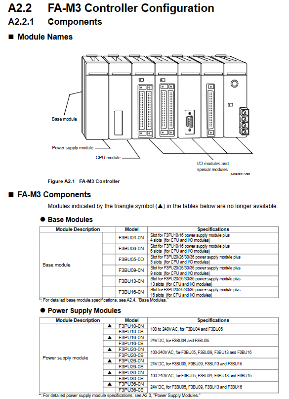
Core components: Basic module, power module, CPU module, I/O module, special module (analog, communication, positioning, etc.), expansion module (fiber FA bus, Ethernet, etc.)
Topology structure: Main unit (No. 0, including 1 main CPU module, supporting up to 3 extended CPU modules)+Slave units (No. 1-7, without CPU modules), supporting a maximum of 8192 I/O points per system
Expansion methods: Fiber FA bus type 2 module (single segment up to 500m), FA bus type 2 module (shielded twisted pair, up to 70m)
2. Module installation restrictions
The power module must be installed in the leftmost slot
The main CPU module is installed in slot 1, and slots 2-4 can accommodate expansion CPU modules or I/O modules
When installing multiple CPU modules, I/O modules cannot be inserted between CPU modules
A single main unit can install up to 4 CPU modules (1 main CPU+3 expansion CPUs)
(2) Core module specifications
1. Basic module (slot carrier)
Model, number of slots, compatible with power module weight
F3BU04-0N 4 (1 power supply+3 I/O/CPU) F3PU10/16 series 150g
F3BU06-0N 6 (1 power supply+5 I/O/CPU) F3PU10/16 series 210g
F3BU05-0D 5 (1 power supply+4 I/O/CPU) F3PU20/26/30/36 series 210g
F3BU09-0N 9 (1 power supply+8 I/O/CPU) F3PU20/26/30/36 series 340g
F3BU13-0N 13 (1 power supply+12 I/O/CPU) F3PU20/26/30/36 series 470g
F3BU16-0N 16 (1 power supply+15 I/O/CPU) F3PU20/26/30/36 series 550g
2. Power module (power core)
Divided into two categories: AC input and DC input, the core specifications are as follows:
Type Model Series Input Voltage Rated Output Compatible Basic Module
AC input F3PU10-0N/0S 100-240V AC 5V DC, 2.0A F3BU04/06
AC input F3PU20-0N/0S 100-240V AC 5V DC, 4.3A F3BU05/09/13/16
AC input F3PU30-0N/0S 100-240V AC 5V DC, 6.0A F3BU05/09/13/16
DC input F3PU16-0N/0S 24V DC 5V DC, 2.0A F3BU04/06
DC input F3PU26-0N/0S 24V DC 5V DC, 4.3A F3BU05/09/13/16
DC input F3PU36-0N/0S 24V DC 5V DC, 6.0A F3BU05/09/13/16
Key features: Supports 20ms instantaneous power-off tolerance, leakage current ≤ 3.5mA (AC type), insulation resistance ≥ 5M Ω, with FAIL signal contact output (24V DC, 0.3A)
3. CPU module (control core)
Covering four major categories: sequential CPU, BASIC CPU, OS free CPU, and IEC61131-3 CPU, with core parameter examples:
Type Model Example Program Capacity Basic Instruction Execution Time Core Functions
Sequence CPU F3SP21-0N 10K ladder step 0.18-0.36 μ s/step basic logic control
Sequential CPU F3SP59-7S 254K trapezoidal step 0.0175-0.07 μ s/step large capacity high-speed control
BASIC CPU F3BP30-0N 510KB BASIC - Supports BASIC programming language
OS free CPU F3RP70-2L - No operating system, flexible customization
IEC61131-3 CPU F3NP5 □□□□ - Compatible with IEC61131-3 standard
Expansion features: Some models support network functions (Ethernet, PROFIBUS-DP), ROM package expansion storage
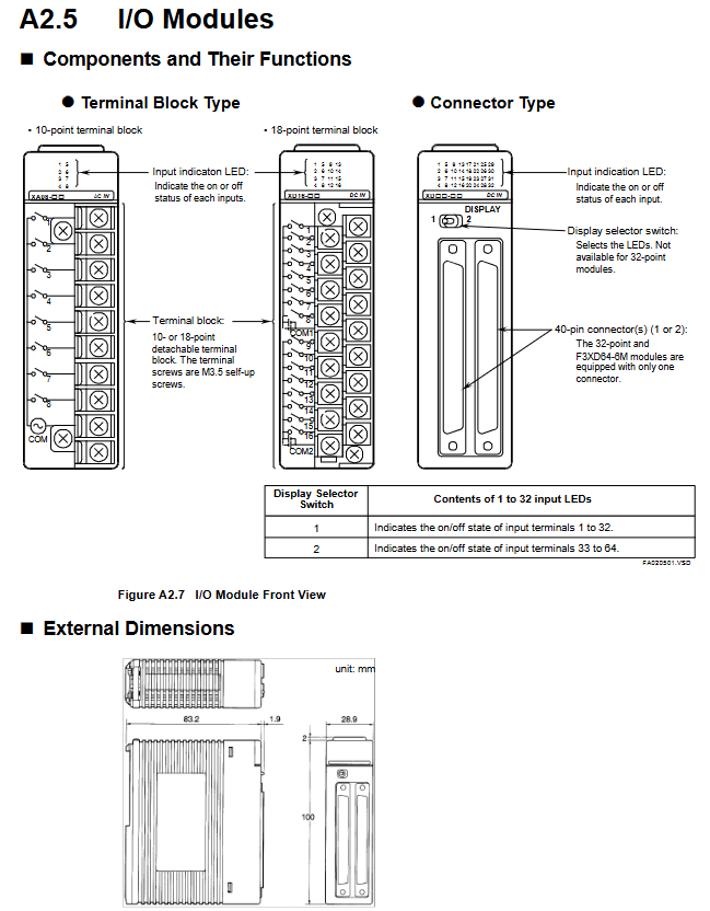
4. I/O module (signal interaction)
Covering three major categories: digital quantity, analog quantity, and special functions, the core sub modules are as follows:
Digital input module: F3XH04-3N (high-speed 4-point), F3XA08-1N (AC 8-point), F3XD series (DC 8-64 points, supporting drain/source input)
Digital output module: F3YA08-2N (bidirectional thyristor 8-point), F3YC series (relay output), F3YD series (transistor output, with short-circuit protection)
Analog module: F3AD series (input 4-8 points, 12-16 bit accuracy), F3DA series (output 2-8 points, 12-16 bit accuracy)
Special modules: F3CT series (temperature control), F3XP series (high-speed counter), F3NC series (positioning control, supporting 1-15 axes)
Key features: Isolation method includes optocoupler/mechanical/transformer isolation, with a withstand voltage of 1500V AC (optocoupler/mechanical) or 500V AC (transformer)
5. Expansion and Communication Module
Communication modules: Ethernet (F3LE series, 10/100Mbps), PROFIBUS-DP (F3LB01-0N), DeviceNet (F3LD series) Modbus(F3LC31-2F)
Remote I/O modules: YHSLS main module (F3LH series, 12Mbps, up to 252 slave stations), fiber FA bus module (F3LR series, 10Mbps)
(3) Auxiliary components
ROM package: RK series, stores programs/data, supports 5K-254K ladder steps, compatible with serial CPUs and BASIC CPUs
Cable: Programming tool cable (KM11 series), fiber optic cable (KM60/KM61 series), terminal block cable (KM55 series)
Terminal blocks: TA40-0N (40 points, European type), TA50 series (40 points, DIN rail installation), TA60-0N (40 points, compact type)
Key technical parameters
(1) Environmental and physical parameters
Category specifications
Working temperature 0-55 ℃ (some modules require a narrower range), storage temperature -20-75 ℃
Relative humidity 10-90% RH (non condensing)
Installation requirements for indoor use, metal panel enclosure (protection level IK08 or above)
The highest altitude is 2000m
Anti vibration 10-57Hz amplitude 0.075mm, 57-150Hz acceleration 9.8m/s ² (10 times in X/Y/Z directions)
Anti impact acceleration of 147m/s ² (98m/s ² for DIN rail installation), 3 times in X/Y/Z directions each
(2) Electrical parameters
Power supply fluctuation: AC power supply 85-264V, DC power supply 15.6-31.2V
Voltage resistance: power terminal - grounded 1500V AC/1 minute, signal terminal - grounded 1000V AC/1 minute
Leakage current: ≤ 3.5mA (AC power module)
Insulation resistance: ≥ 5M Ω (tested at 500V DC)
Allow instantaneous power outage: Standard mode up to 20ms, immediate detection mode up to 2-10ms (depending on power module model)
(3) Performance indicators
CPU processing speed: Basic instructions 0.00375 μ s-0.36 μ s/step (depending on model)
I/O response time: The fastest digital quantity is 50 μ s, and the fastest high-speed module is 0.1ms
Communication speed: Ethernet up to 100Mbps, PROFIBUS-DP up to 12Mbps, YHSLS up to 12Mbps
Scalability: Up to 7 slave units, 32 FA link H module sites, and a maximum of 8192 I/O points per system
Installation and wiring specifications
(1) Installation requirements
1. Fixed method
DIN rail installation (F3BU04/06/05/09/13) or M4 screw fixation (all models)
F3BU16-0N only supports screw fixation and does not support DIN rails
2. Installation gap and space
Vertical installation spacing ≥ 8cm, unobstructed upper and lower ventilation openings
The module installation needs to be tightened to the buckle lock, and additional screws are required to fix it in the vibration environment
Installation of fiber optic modules requires reserved bending radius: temporary laying of fiber optic cables ≥ 15mm, fixed laying ≥ 50mm; temporary laying of fiber optic cables ≥ 50mm, fixed ≥ 100mm
3. Environmental adaptation
Avoid direct sunlight and stay away from heat sources such as transformers and electromagnetic switches
Space heaters are required for condensation risk environments, and preheating is necessary before starting at low temperatures
(2) Wiring specifications
1. Conductor requirements
Only copper conductors are allowed, with a cross-sectional area of 0.33-2.1mm ² (AWG14-22)
Conductor temperature resistance ≥ 75 ℃, grounding cable cross-sectional area ≥ 2mm ²
2. Terminal torque
M3 screw: 0.8N · m, M3.5 screw: 0.8-1.2N · m, M4 screw: 1.2N · m
Terminal block screw tightening torque 0.22-0.6N · m (depending on model)
3. Anti interference measures
The distance between power cables and signal cables is ≥ 20cm, and analog and digital signals are routed in separate slots
Both ends of the shielded cable should be grounded, and the signal cable should be kept away from the power cable (≥ 20cm)
The input line of the power module adopts twisted pair cable and is equipped with ferrite core (in noisy environment)
4. Grounding requirements
Protective grounding (FG): connected to a protective grounding grid that complies with national standards, with a grounding resistance of ≤ 100 Ω
Functional grounding (FG): Low impedance grounding, CE compliance requires the use of braided wire
The LG terminal (line filter grounding) needs to be properly grounded, otherwise it may generate a half wave potential
(3) CE/UL/UKCA compliance requirements
EMC compliance: EN 61326-1 Class A, EN 55011 Class A, for use in industrial environments (residential environments require additional anti-interference measures)
LVD compliance: EN 61010-1, EN IEC 61010-2-201, overvoltage category II, pollution level 2
RoHS compliance: EN IEC 63000 standard
UKCA certification: The importer for the UK market is Yokogawa United Kingdom Limited
Testing and maintenance process
(1) Test running steps
Installation inspection: The module is securely installed, the panel is well ventilated, and the gap meets the requirements
Wiring inspection: correct polarity, terminal tightening, shielding layer grounding, cable routing compliance
Insulation test: 500V DC megohmmeter test, insulation resistance ≥ 5M Ω
Power supply test: Measure the power supply voltage and confirm that it meets the module input requirements
Power on test: If the power indicator light (RDY) is constantly on, it is normal. Check that the module has no abnormal heating
Functional testing: First test the emergency stop and other safety circuits → Single module functional testing → System linkage testing → Automatic operation testing → Fault simulation testing
(2) Maintenance points
1. Regular maintenance
Cleaning: Wipe the panel with a soft cloth and neutral detergent to prevent moisture from entering the interior of the module
Inspection: Regularly check cable connections, terminal fastening, and module indicator light status
Spare parts replacement: Modules that have been in use for over 10 years require preventive replacement; The built-in lithium battery in the CPU module (with a lifespan of ≥ 10 years at room temperature) needs to be checked regularly
2. Fault handling
Self diagnostic function: After the CPU module is powered on, it automatically performs hardware initialization, RAM check, and I/O configuration check. When there is a fault, it prompts through indicator lights and error codes
Common faults: abnormal power supply (check voltage/fuse), communication faults (check cables/grounding), I/O unresponsive (check wiring/module installation)
Error code: including Error (1-4) and Alarm (6-10) series, corresponding to voltage, temperature, A/D conversion, memory and other faults respectively
3. Module replacement
Power off operation: Before plugging or unplugging modules, the power must be turned off to avoid damaging components
Replacement note: Use designated spare parts from Yokogawa, and perform functional testing again after replacement
Safety and compliance requirements
(1) Key points for safe operation
Power off operation: Before wiring or plugging in modules, the power must be turned off to avoid electrical shock
High temperature protection: Some modules may experience high temperatures during operation, and protective gloves should be worn during maintenance
Load limit: The output module must not exceed the rated current (transistor type 0.1A-2A/point, relay type 2A/point)
Prohibition of modification: It is not allowed to modify the internal circuit or shell of the module, otherwise the safety guarantee will be lost
Safety circuit: An external relay must be connected to achieve emergency stop circuit interlocking, which is linked to the operation status of the controller
(2) Waste disposal (EU/UK region)
Equipment disposal: Do not dispose of as household waste, contact the local Yokogawa office for disposal in accordance with environmental regulations
Battery disposal: The module has built-in lithium batteries (lithium classification), and batteries that can be disassembled by users need to be separately classified and recycled; Non removable to be disposed of together with the equipment
WEEE Compliance: Complies with the requirements of the WEEE Directive, with product labeling featuring a dedicated recycling label
(3) Software Usage Specification
Software authorization: For single computer use, additional authorization is required for multiple devices
Prohibited behaviors: Reverse engineering (such as decompilation), unauthorized copying/transfer/leasing of software are prohibited
Backup requirements: The original software media must be securely stored and only copies for backup purposes are allowed
Key accessories and spare parts
(1) Core attachments
Category Model Example Usage
Programming tool cable KM11-2T/KM13-1S connects PC and CPU modules for program download/debugging
Fiber optic cable KM60-001/KM61-100 module to module extended communication, suitable for indoor/outdoor use
Terminal block cable KM55-005/KM55-030 connects I/O module and terminal block, length 0.5-3m
Terminal block TA40-0N/TA50-0N I/O signal adapter, supports screw fixation/DIN rail installation
(2) Common spare parts
Spare part name, part number, applicable scenarios
Fuse A1113EF power module overcurrent protection (3.15A delay type)
Terminal A1474JT/T9113PF 10/18 point terminal block replacement
Dust proof connector cover T9031AS module connector dust protection
Rail Installation Kit T9031AP/T9031AQ Basic Module DIN Rail Installation and Fixation
Shielding clip FGC series shielded cable grounding fixation
- OMRON
- ABB
- General Electric
- EMERSON
- Honeywell
- HIMA
- ALSTOM
- Rolls-Royce
- MOTOROLA
- Rockwell
- Siemens
- Woodward
- YOKOGAWA
- FOXBORO
- KOLLMORGEN
- MOOG
- KB
- YAMAHA
- BENDER
- TEKTRONIX
- Westinghouse
- AMAT
- AB
- XYCOM
- Yaskawa
- B&R
- Schneider
- KONGSBERG
- NI
- WATLOW
- ProSoft
- SEW
- ADVANCED
- Reliance
- TRICONEX
- METSO
- MAN
- Advantest
- STUDER
- DANAHER MOTION
- Bently
- Galil
- EATON
- MOLEX
- DEIF
- B&W
- ZYGO
- Aerotech
- DANFOSS
- Beijer
- Moxa
- Rexroth
- Johnson
- WAGO
- TOSHIBA
- BMCM
- SMC
- HITACHI
- HIRSCHMANN
- Application field
- XP POWER
- CTI
- TRICON
- STOBER
- Thinklogical
- Horner Automation
- Meggitt
- Fanuc
- Baldor
- SHINKAWA
- Other Brands
- UniOP
- KUKA
- Iba
- Beckhoff
-
 Basler D90 96801 100 PCB Card
 -
 Basler XR2002F Voltage Regulator (110 VAC, 48-480 Hz)
 -
 Basler SR8A-2B14B3A Regulator
 -
 Basler 9561500100 Module
 -
 Basler DECS-400 BE1-11 System
 -
 Basler DECS-100-B15 Excitation Control
 -
 Basler SCP 210 Frequency Controller
 -
 Basler SR4A-2B15B3A Static Voltage Regulator
 -
 Basler BE1-32R Power Relay
 -
 Basler PIA2400-17GM Power Interface Adapter
 -
 Basler MVC 232 Manual Voltage Control Module
 -
 Basler SSR 32-12 Static Voltage Regulator
 -
 Basler 5MW AVR Generator Voltage Regulator
 -
 Basler VR63-4B Voltage Regulator
 -
 Basler DECS-100-A05 AVR for Engine Generator
 -
 Basler DECS-100-B15 Automatic Voltage Regulator
 -
 Basler BE1-32R Directional Power Relay
 -
 Basler BE1-87B Differential Relay
 -
 Basler UFOV 260A Protective Module
 -
 Basler 9-2614-02-100 PCB Rev M
 -
Basler DECS-100-B15 Digital AVR
-
 Basler 9284900103 PS DECS-400N
 -
 Basler D4N3H1U Intertie Protection
 -
 Basler DECS-100-B15 A15 AVR
 -
 Basler KR4F Voltage Regulator
 -
 Basler BE26434 T14 Transformer
 -
 Basler SR8A-2B15B3A Regulator
 -
 Westinghouse 774B472A12 AR Relay
 -
Basler DECS-100-B15 AVR
-
Basler XR2002F Regulator 110V
-
Basler SR125-E Static Regulator
-
 Basler SSR 125-12 Regulator
 -
 Basler MOC2599 Motor Pot
 -
 Basler BE1-DFPR Feeder Relay
 -
 Basler CBS 305 Current Boost
 -
 Basler BE1-25 AutoSync
 -
 Basler MVC 300 Voltage Control
 -
 Basler BE3-25A AutoSync
 -
 Basler KR7FF Static Regulator
 -
 Basler 90-49000-100 Regulator
 -
 Basler 880 kVA Dry Type Transformer Specs
 -
 Basler Electric BE1-25 Sync-Check Relay Specs
 -
 Basler SSR 125-12 Voltage Regulator Specs
 -
 Basler Electric BE1-851 Overcurrent Relay Review
 -
Basler Electric 149D930G02 Control Sub-Assembly
-
 Basler Electric BE1-81O/UT Frequency Relay Specs
 -
 Basler Electric BE1-51/27C Overcurrent Relay
 -
 Basler Electric 149D956G02 Industrial Component
 -
Basler Electric BE1-51A Overcurrent Relay Specs
-
 Basler Electric BE1-40Q Loss of Excitation Relay
 -
 Basler DECS-200 Excitation Control System
 -
 Basler DECS-200 Voltage Regulator 56-277V AC / 125V DC
 -
Basler BE1-87T Transformer Differential Relay
-
 Basler RDP-110-S1 Protection Relay
 -
 Basler BE1-700V Digital Protective Relay
 -
 Basler BE1-951 Overcurrent Protection System
 -
 Basler DECS-300 Digital Excitation Control
 -
 Basler DECS-200 Digital Excitation Control
 -
 Basler DECS-200-1C Excitation Control System
 -
Basler DECS-200-1L Digital Excitation Control
-
 Basler Electric BE1-GPS Generator Protection System
 -
Basler Electric DECS-200-1C Digital Excitation Controller
-
 Basler Electric DECS125-15 Excitation Control with Power Module
 -
 Basler Electric BE1-87G Differential Relay
 -
 Basler Electric BE1-11 Protection System I5A3M2P2N0EA00
 -
Basler Electric DECS-200-1C Excitation Control System
-
Basler Electric BE1-11g Generator Protection Relay
-
Basler Electric DECS 125-15-B2C1 V2.0.9 Excitation Control
-
 Basler Electric BE1-81O/UT3ED1JA7N2F Frequency Relay
 -
Basler Electric BE1-81O/UT3EE1YB7N1F Frequency Relay
-
 Basler Electric DECS-200-1L Digital Excitation Control System
 -
Basler DECS125-15-B2C1 Excitation Control
-
 Basler 9507900205 SSR Retrofit Voltage Regulator
 -
 Basler BE2000E Digital Voltage Regulator
 -
 Basler BE1-GPS Generator Protection System
 -
Basler DECS-250-CN1CN1N Digital Excitation Control
-
 Basler DGC-2020 Genset Controller
 -
 Basler BE1-81O UT3ED1LA7N0F Frequency Relay (Variant)
 -
 Basler BE1-81O UT3EE1YA9S0F Frequency Relay (Variant)
 -
Basler BE1-81O Over/Under Frequency Relay
-
Basler DECS125-15 Digital Excitation Control
-
Basler Electric BE1-951 Overcurrent Protection System
-
 Basler Electric BE1-700V Digital Protective Relay
 -
 Basler Electric APR63-5 Automatic Voltage Regulator
 -
Basler Electric BE1-851 Overcurrent Protection System
-
Basler Electric DECS-250-LN1SN1N Excitation Control
-
 Basler Electric BE1-87T Transformer Differential Relay
 -
Basler Electric DECS-200-1L Excitation Control System
-
 Basler Electric 9310300100 DECS-300 Excitation Control
 -
 Basler Electric SSE-N 125-4.5KW Shunt Exciter Regulator
 -
 Basler Electric DGC-2020HD-5NS1DNSBA Genset Controller
 -
Basler Electric BE1-81-O/UT3EE1JB7N1F Frequency Relay
-
Basler Electric BE1-81T1EE1WA0N1F Frequency Relay
-
 Basler Electric BE1-25M1EA6PN5R1F Sync-Check Relay
 -
 Basler Electric BE1-GPS Generator Protection System
 -
Basler Electric DECS-250-LN1SN1N Excitation Control Rev V
-
 Basler Electric DECS-250-CN2CN1N Excitation Control
 -
Basler Electric BE1-50/51B-207 Overcurrent Relay
-
Basler Electric DECS-300-C0N0 Excitation Control System
-
Basler Electric DECS-200 Digital Excitation Control System
-
Basler Electric DECS-250-LN1CN1N Excitation Unit
-
Basler Electric DECS-250 LN2SA1D Excitation Unit Specs
-
Basler Electric BE1-87T Transformer Relay Review
-
Basler Electric BE1-11 Protection System
-
Basler Electric BE1-GPS100-E4N1H1N Protection System
-
 Allen-Bradley 442G-MABH-R Safety Module
 -
 Beckhoff CX1030-0111 PLC Assembly Profile
 -
 FANUC IC693CPU364 PLC Module
 -
 Orange Denmark Type 200816 220 PLC Specs
 -
 OMRON C200H-SNT31 Sysmac PLC Module
 -
 Allen Bradley 20AB022A3AYNANC0 PowerFlex 70
 -
 OMRON C200HW-PCU01 Position Control Unit
 -
 ABB AO845A-eA Analog Output Module
 -
 OMRON CJ1M-CPU22 CPU Unit
 -
 Allen Bradley 100-E265ED11 Contactor
 -
 Honeywell 51304511-100 Interface Module
 -
 SOLEXY BXF3S0101N0018 Gateway Module
 -
 OMRON CJ2H-CPU65 CPU Unit
 -
 Automation Direct GS2-45P0 AC Drive
 -
 M68-2000 2-Axis Motion CNC Controller
 -
 OMRON CJ1M-CPU11 V3.0 PLC CPU Unit
 -
 OMRON CJ1W-NC413 4-Axis Positioning Controller
 -
 OMRON 3G2A3-PRO16 Programming Console HMI
 -
 Siemens 3VT8440-2AA04-2GA2 Molded Case Circuit Breaker
 -
 Siemens 3RT5045 Contactor Series
 -
 OMRON C200HS-CPU01-E SYSMAC PLC Controller
 -
 OMRON C500-NC103-E Positioning Control Unit
 -
 OMRON CJ1W-TC001 Temperature Control Unit


