
WOODWARD easYgen-3000 Series (Package P1) Genset Control
WOODWARD easYgen-3000 Series (Package P1) Genset Control
Core positioning and basic information
The Woodward easyYgen-3000 series (Package P1) generator set controller is a multifunctional control unit designed for general and marine scenarios. Manual 37223E (software version 1.10xx) serves as an exclusive installation guide, focusing on hardware installation, wiring configuration, physical parameters, and safety specifications of the equipment, without involving parameter configuration and daily operation details. The product covers four core models (8440-1816/1817/1818/1831), which have undergone multiple revisions from A to E. The main focus is on optimizing the installation instructions and correcting details of the shell, ultimately forming a complete installation guidance system. Its core value lies in providing precise electrical parameter measurement, flexible input-output control, and reliable communication interconnection for generator sets, adapting to multi scenario application needs from ordinary computer rooms to ship decks.
Hardware structure and installation specifications
1. Shell type and core parameters
The product offers two differentiated shell designs, suitable for different installation scenarios:
Shell type corresponds to model, core feature size (W × H × D), protection level, installation method
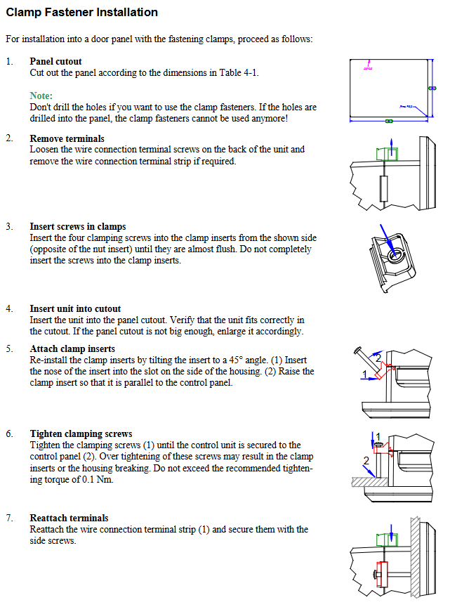
Plastic shell easyYgen-3200 with graphic LCD display screen, supports local operation 282 × 217 × 99mm fixture fixing IP54; Screw kit IP66 panel embedded installation, hole size 249 × 183mm (tolerance+1.1/+1.0mm)
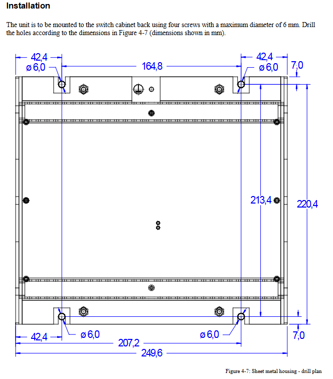
Metal shell easyYgen-3100 without display screen, focusing on integrated installation 249.6 × 227.4 × 84.1mm IP20 cabinet back installation, fixed with 4 M6 screws
2. Key installation requirements
Torque control: Plastic shell screws require 0.6Nm for fixation, fixtures require 0.1Nm for fixation; metal shell and terminal wiring require 0.5Nm to avoid damage to components due to over tightening
Wiring specification: Only 60/75 ℃ copper wire is allowed, with a maximum wire diameter of 2.5mm ² (14AWG), and the terminal load capacity needs to be matched
Static electricity protection: Before contacting the circuit board, it is necessary to release human static electricity to avoid synthetic materials from approaching the equipment; The PCB board should always be in anti-static packaging and only be operated with the edge in hand
Ship scene adaptation: The metal shell directly complies with LR/ABS classification society certification; The plastic shell needs to be fixed with 12 screws and an EMI filter (such as TIMONTA FSS2-65-4/3) should be installed in the bridge/deck area
3. Terminal layout and interface distribution
The back terminals of the device are designed according to functional zoning, including the power supply area (61-65 terminals), measurement area (1-40 terminals), input/output area (41-80 terminals), and communication area (independent interface). Among them:
The protective grounding (PE) terminal 61 is only effective on plastic shell models, and the metal shell needs to be grounded through the shell to achieve protection
Centralized layout of relay output and discrete input terminals for easy wiring organization; Separate partition of analog signal terminals to reduce interference
The communication interface (RS-232/RS-485/CAN) adopts standard D-SUB/IDC interface, with reserved shielding layer connection points to enhance anti-interference capability
Core Electrical Configuration and Wiring Guide
1. Power supply system configuration
Main power supply: Supports 12/24VDC wide voltage input (8-40Vdc), with a maximum power consumption of 17W. A 6A slow melting fuse (such as NEOZEN D01 6A) or a C-type miniature circuit breaker (such as ABB S271C6) needs to be connected in series in the power supply line
Auxiliary power supply: Terminal 65 provides pre excitation output (D+) for the charging generator, which excites the generator during startup and monitors the charging voltage during operation
Grounding requirements: The voltage difference between the negative terminal of the battery and the PE terminal shall not exceed 15V, and an isolated external power source shall be used if it exceeds this limit; Ship scenarios require additional access to independent safety protection devices that comply with classification society regulations
2. Measurement system wiring (voltage/current/power)
(1) Voltage measurement (FlexRange dual range)
Supports voltage measurement for generators, power grids, and busbars, covering various wiring methods such as 1Ph 2W/3W, 3Ph 3W/4W, etc. The core specifications are as follows:
Range selection: 100V range (50-130Veff) is suitable for low voltage scenarios, 400V range (131-480Veff) is suitable for high voltage scenarios, and it is strictly prohibited to connect two sets of ranges at the same time
Wiring requirements: The generator voltage is connected through terminals 29-36, the grid voltage is connected through terminals 21-28, and the bus voltage is connected through terminals 37-40; The N line needs to be wired separately to avoid measurement errors caused by different voltage systems sharing the N terminal
Protective measures: It is recommended to connect 2-6A slow melting fuses in series for all voltage inputs, and withstand surge voltages of 2.5kV at 100V and 4.0kV at 400V
(2) Current measurement (CT secondary side adaptation)
Support measurement of three-phase current for generators, single-phase current for power grids, and grounding current. Core specifications:
Rated input: compatible with 1A/5A CT secondary side signals, generator current is connected through terminals 3-8, and grid/ground current is connected through terminals 1-2
Wiring specification: The CT secondary side needs to be grounded at a single point (near the CT end), and the CT terminal must be short circuited before disconnecting the equipment to prevent high voltage caused by an open circuit
Measurement range: The linear measurement range of the generator current reaches 3 times the rated value, and the grid/ground current reaches 1.5 times the rated value, with an accuracy of Class 1
(3) Power and power factor measurement
Power measurement: Based on voltage/current signal derivation, the active power range is -2~2GW, the reactive power range is -2~2Gvar, and the accuracy is 2%. Zero crossing detection is required to ensure measurement accuracy
Power factor: defined from the perspective of a generator, the inductive load displays lag (lg) and the capacitive load displays lead (ld), which can be used as the basis for voltage regulation (capacitive overload outputs boost signal, inductive overload outputs buck signal)
3. Input/output interface configuration
(1) Discrete input (12 channels, terminals 66-78)
Electrical characteristics: Electrical isolation design, supporting positive/negative polarity signals, input resistance ≈ 20k Ω, working voltage 8-40Vdc
Pre allocation function: Core inputs such as DI01 (emergency stop signal), DI02 (automatic start), DI03 (low oil pressure alarm) have predefined functions, and DI07-DI08 are fixed as MCB/GCB feedback signals
Operation logic: Can be configured as normally open (N.O.)/normally closed (N.C.), energized when a fault occurs in the normally open state, and de energized when a fault occurs in the normally closed state
Safety reminder: DI01 is only an emergency stop signal input and cannot be directly used as an emergency stop execution function. It needs to independently implement the EN 60204 standard requirements externally
(2) Relay output (12 channels, terminals 41-60)
Hardware parameters: AgCdO contact material, universal load 2A@250Vac /24Vdc, PILOT load 1A@24Vdc Support long-term stable work
Pre allocation functions: R01 (ready to run), R04 (fuel solenoid valve), R05 (preheating), R07/R09 (GCB/MCB opening command), etc., supporting custom functions through LogicsManager software
Safety requirement: The "Ready to Run" output should be connected in series with the emergency stop function to ensure that the generator circuit breaker is disconnected and the engine stops in case of equipment failure
(4) Analog input/output
Analog input (3 channels, terminals 9-14): supports 0/4-20mA, 0-500 Ω, VDO sensor signals, bipolar wiring accuracy ≤ 1%, unipolar wiring accuracy ≤ 2.5%; Bipolar signal ground to PE, unipolar signal ground to engine ground (terminal 62)
Analog output (2 channels, terminals 15-20): Supports ± 10Vdc, ± 20mA, PWM signals, 20mA output maximum load of 500 Ω, resolution 11-12 bits, signal type can be switched through external jumpers
(5) MPU input (terminals 79-80)
Adaptive sensor: Magnetic electric speed sensor (MPU), input impedance ≥ 17k Ω, maximum input frequency 14kHz
Wiring requirements: The cable shielding layer is only grounded at a single point on the device end, and the MPU end is not grounded; Need to match the number of teeth and speed of the flywheel gear to ensure that the input frequency does not exceed the limit
4. Communication interface configuration
Interface Type Quantity Terminal/Interface Form Core Parameters Application Scenarios
RS-232 1-channel D-SUB DE9 electrical isolation, signal level ± 5V local debugging, point-to-point short-range communication
RS-485 1-channel D-SUB DE9 supports half duplex/full duplex, Modbus protocol for multi device networking and remote monitoring
CAN bus 2-channel D-SUB DE9/IDC electrical isolation, baud rate 10k-1Mbit/s industrial equipment interconnection, maximum distance 2500m (20kbit/s)
Key requirements for CAN bus: use shielded twisted pair cables (such as Lappkabel Unitronic LiyCY), with 120 Ω terminal resistors connected at both ends; Avoid parallel wiring with power cables to prevent electromagnetic interference
Environmental adaptability and compliance certification
1. Environmental tolerance
Temperature range: Operating -20 ℃~70 ℃, Storage -30 ℃~80 ℃, Supports low-temperature deck environment on ships
Vibration shock: sine vibration 5-100Hz (4G), random vibration 10-500Hz (1.04Grms), shock 40G (11ms sawtooth wave), in compliance with EN 60255 and MIL-STD 810F standards
Humidity protection: Stable operation for 5 days under 60 ℃ and 95% RH environment, meeting the requirements of high humidity environment for ships
2. Compliance and Certification
Basic certifications: CE, UL (for general locations), cUL (for easyYgen-3100 only), EMC compliant with EN related standards
Ship certification: LR (Lloyd's Register of Shipping), ABS (American Bureau of Shipping), suitable for ENV1-ENV4 Class 4 marine environment
Protection certification: Plastic shell IP66 (screw fixed) can withstand strong water spray, metal shell IP20 compatible for installation in cabinets
Safety regulations and precautions
Electrical safety: Protective grounding (PE) must be connected, with a wire diameter of ≥ 2.5mm ²; Insulation voltage lasts for 100Vac, test for 500Vac (1 second) to avoid leakage risk
Electrostatic protection: The equipment can withstand 85kV electrostatic spraying, but daily operation should avoid direct contact with PCB components; PCB replacement must be carried out in a voltage free environment, and both new and old boards require anti-static packaging protection
Wiring taboos: It is strictly prohibited to connect 100V and 400V voltage inputs simultaneously; CT secondary side cannot be open circuited, and voltage input cannot be short circuited; Separate wiring for different signal types (analog/digital) to reduce interference
Appendix Key Reference Information
CAN bus pin definition: Provides pin allocation for D-SUB DE9, RJ45/8P8C, and IDC interfaces, with CAN-H connected to 7-pin (D-SUB) and 1-pin (RJ45), and CAN-L connected to 2-pin (D-SUB) and 2-pin (RJ45) for easy interconnection of third-party devices
Wire diameter conversion table: including the correspondence between AWG and mm ² wire diameter (such as 14AWG=2.5mm ², 10AWG=6mm ²), for easy selection and matching
Compatible connectors: It is recommended to use narrow body D-SUB housings such as FCT (FKH1/FKC1G) and Wuerth Electronic (618009214622) to avoid interfaces that cannot be inserted
- OMRON
- ABB
- General Electric
- EMERSON
- Honeywell
- HIMA
- ALSTOM
- Rolls-Royce
- MOTOROLA
- Rockwell
- Siemens
- Woodward
- YOKOGAWA
- FOXBORO
- KOLLMORGEN
- MOOG
- KB
- YAMAHA
- BENDER
- TEKTRONIX
- Westinghouse
- AMAT
- AB
- XYCOM
- Yaskawa
- B&R
- Schneider
- KONGSBERG
- NI
- WATLOW
- ProSoft
- SEW
- ADVANCED
- Reliance
- TRICONEX
- METSO
- MAN
- Advantest
- STUDER
- DANAHER MOTION
- Bently
- Galil
- EATON
- MOLEX
- DEIF
- B&W
- ZYGO
- Aerotech
- DANFOSS
- Beijer
- Moxa
- Rexroth
- Johnson
- WAGO
- TOSHIBA
- BMCM
- SMC
- HITACHI
- HIRSCHMANN
- Application field
- XP POWER
- CTI
- TRICON
- STOBER
- Thinklogical
- Horner Automation
- Meggitt
- Fanuc
- Baldor
- SHINKAWA
- Other Brands
- UniOP
- KUKA
- Iba
- Beckhoff
- ADLINK
-
 Basler Electric BE1-700 Digital Protective Relay
 -
 Basler Electric SR8A-2B01B3A Static Voltage Regulator
 -
 Basler Electric SR4A-2B01B3E Static Voltage Regulator
 -
 Basler Electric 9017709102 PC Board
 -
Basler Electric SR4A-2B01B3A Static Voltage Regulator
-
 Basler Electric PRS-250 Veri-Sync Relay
 -
 Basler Electric 9066800102 Excitation Support System
 -
 Basler Electric BE1-87G Generator Differential Relay 9 1708 18 100
 -
 Basler Electric 36T865-2 BE03752001 Power Supply
 -
 Basler Electric M-300 149D940G02 Power Supply
 -
 Basler Electric ACA2040-25GM 4Mp 25Fps Area Scan Camera
 -
 Basler BE1-87G-S1A-A1C-A0N0 Differential Relay
 -
 Basler SR8A-2B06B3E Static Regulator SR8A2B06B3E
 -
 Basler SCP-210 Frequency Controller 9095400100
 -
 Basler BE1-59-A3E-A1J-N1N3F Overvoltage Relay BE159A3EA1JN1N3F
 -
 Basler 9 2011 11 100 Bracket Mounted Terminal Unit
 -
Basler 9 1606 00 101 Voltage Regulator
-
 Basler CBS-377 Current Boost System 9109600102
 -
 Basler 8650C72 Exciter Control Module PCB Rev 5
 -
 Basler C2EE1PA0N1F BE1-32R Reverse Power Relay
 -
 ADLINK HPCI-14S12U - Industrial Control Backplane 12PCI Backplane PCI-14S Passive Backplane
 -
-0010.png) ADLINK PCIe-GIE74C - image acquisition card 4-CH GigE Vision PoE+ Frame Grabber
ADLINK PCIe-GIE74C - image acquisition card 4-CH GigE Vision PoE+ Frame Grabber -
-0010_1.png) ADLINK PCI-8164 - control card 4-Axis Advanced Motion Controller Board
ADLINK PCI-8164 - control card 4-Axis Advanced Motion Controller Board -
 ADLINK PCIe-U304 - 4 Port USB3 PCIe Frame Grabbers USB Screw Hole Card
 -
 ADLINK PCI-9112 - Multi-Function Data Acquisition Card DAQ Card
 -
 ADLINK PCI-7432 - 51-12013-0A50 4-CH Isolated Numérique I/O PCI Cartes Digital I/O Card
 -
 ADLINK PCA-6106P3-0C1 REV.C1 - backplane 6-Slot Passive Backplane Board
 -
 ADLINK PCI-7224 - 24-CH Opto-Isolated Digital I/O PCI Board
 -
 ADLINK CPCI-7433R(G) - Digital Input Board Rear I/O CompactPCI Card
 -
 ADLINK EBP-13E4 - 51-46703-0A30 Industrial PC Backplane Passive Backplane
 -
 ADLINK PCIE-HDV62 - Image acquisition card High Definition Video Frame Grabber
 -
 ADLINK EBP-13E4 - 51-46703-0A30 Industrial Backplane Board Passive Backplane
 -
 ADLINK 90111-B1 / CPCI-6770 - PCB CPU MODULE CompactPCI Single Board Computer
 -
 ADLINK PCI-7248 - DATA ACQUISITION PCI CARD 48-CH Parallel Digital I/O Board
 -
 ADLINK PCI-7230 - 51-12003-0a50 board PCI7230 32-CH Isolated Digital I/O Card
 -
 ADLINK PCI2A000CB - 51-20000-0B30 Multi-Function DAQ Card Baseboard
 -
 ADLINK PCI-8134-005 - 4-Axis Motion Controller Card
 -
 ADLINK PCI-7224 - 24-CH Opto-Isolated Digital I/O PCI Card
 -
 ADLINK PCI-7434 - 64-CH Isolated Digital Output Card
 -
 ADLINK PCI-8132 - motion control card 2-Axis Servo & Stepper Controller
 -
 ADLINK PCI-8134 - Motion Controller PCI Card 4-Axis Controller Board
 -
 ADLINK PCI-8164 - Motion Control Card 51-12406-0A40 4-Axis Controller
 -
 ADLINK 51-12001-0C20 - Circuit Board Data Acquisition Interface Module Hardware
 -
 ADLINK NuPR0-840 - industrial control motherboard Full-Size PICMG CPU Board
 -
 ADLINK PCI-7444 - 51-12023-0A10 card 128-CH Isolated Digital Output Board
 -
 ADLINK PCI-1612B - data acquisition card 4-Port RS-232/422/485 Serial Communication Card
 -
 ADLINK PCI-6208V 009 - 8/16-CH 16-Bit Analog Output Cards PCB-I-E-482=6BX3
 -
 ADLINK NUPRO-935A/LV - industrial control motherboard Full-Size PICMG SBC Board
 -
 ADLINK PCI-9114DG - Multi-Function DAQ Card Data Acquisition PCI Card
 -
 ADLINK ACL-7130 - Data acquisition card Isolated Digital I/O Board
 -
 ADLINK ABX-6300D-4E1-BP - board ABX6300D4E1BP Video Interface Expansion Card
 -
 ADLINK CPCI-6940 - CPCI-6940/D1539/M16-0(EA)-000E 6U CompactPCI Processor Board
 -
 ADLINK NuPRO-760 - industrial control motherboard Half-Size PICMG SBC CPU Board
 -
 ADLINK IMB-M42H (G)-0020 - industrial control motherboard LGA1155 Micro-ATX Mainboard
 -
 ADLINK RTV-24 / PCI-MP4S - 51-12519-1C30 4-Channel Real Time Video Capture Board
 -
 ADLINK PCI-8134 - 4-Axis Servo & Stepper Motion Controller Card
 -
 ADLINK MXC-6101D - V.PC000.002.ST.00 Box PC Configurable Embedded Computer
 -
.png) ADLINK PCI-8134A - 51-12421-0A10 Motion Control Card 4-Axis Controller Card
ADLINK PCI-8134A - 51-12421-0A10 Motion Control Card 4-Axis Controller Card -
 ADLINK DIN-100S / DIN-100SA1 - Technology SCSI-II TB 100-PIN Terminal Block Board
 -
.png) ADLINK DIN-812M001 / DIN812M001 - 51-14034-0A1 51140340A1 Terminal Module Breakout Interface
ADLINK DIN-812M001 / DIN812M001 - 51-14034-0A1 51140340A1 Terminal Module Breakout Interface -
_1.png) ADLINK PCI-8164 - Servo motion control 4-Axis Advanced Controller Card
ADLINK PCI-8164 - Servo motion control 4-Axis Advanced Controller Card -
 ADLINK PCIe-GIE64 - Acquisition card GigE Vision PoE+ Frame Grabber
 -
 ADLINK M-302 - Industrial control motherboard ATX PC Board Mainboard
 -
 ADLINK PCI-8134 - Motion Controller PCI Card 4-Axis Controller Board
 -
 ADLINK PCI-RTV24 - Image capture card Analog Video Frame Grabber
 -
 ADLINK PCI-8102 - Motion control card 2-Axis Servo & Stepper Controller Board
 -
 ADLINK PCI-9112 REV.B1 - Card Multi-Function Data Acquisition Card
 -
 ADLINK HSI-DI32-M-N / HSL-TB32-M-DIN - Discrete I/O MODULE Distributed Automation Module System
 -
 ADLINK PCI-7296 - IO card REV.A3 96-CH Parallel Digital I/O Card
 -
-0020.png) ADLINK DIN-814P-A4 / 814Y - terminal board Motion Control Interface Block
ADLINK DIN-814P-A4 / 814Y - terminal board Motion Control Interface Block -
 ADLINK DIN-814P-A4 - 51-14056-0A10 PCB-I-E-2736=ZA01 Screw Terminal Board Breakout
 -
 ADLINK M-322 - motherboard Industrial Control Computer Mainboard
 -
 ADLINK NUPRO-406 REV:B1 - industrial control motherboard Full-Size PICMG CPU Board
 -
 ADLINK AMP-204C - card DSP-Based 4-Axis Advanced Pulse-Train Controller
 -
 ADLINK HPCI14S REV.B1 - industrial computer baseboard 14-Slot Passive Backplane
 -
 ADLINK PCI-7250 - 8-CH Relay Output & 8-CH Isolated DI PCI Card
 -
 ADLINK EBP-13E2 - baseplate Passive Backplane Industrial Computer Chassis Board
 -
 ADLINK LPCI-3488A - PCI-GPIB card 51-12801-0A30 acquisition card IEEE-488 Interface Board
 -
 ADLINK PCI-6216V-GL - 51-12201-0C30 16-CH 16-Bit Voltage Analog Output Card
 -
 ADLINK ACL-8454 - 16-CH Isolated Digital I/O & 4-CH Counter Card
 -
 ADLINK HPCI-9S7U - backplane Passive Backplane Compatible with NuPRO-A301 852 841 842
 -
 ADLINK DAQ-2010-007 - Simultaneous-Sampling Multi-Function Data Acquisition Card
 -
 ADLINK MP-C154 - 51-64205-0A10 Motion Control Card 4-Axis Controller Board
 -
 ADLINK MXE-202/mSSD16B/WiFi-BT - Matrix Rugged I/O Platform Embedded Fanless Computer
 -
 ADLINK CM-920-R-17 - PC/104-Plus Single Board Computer Module Intel Celeron M
 -
 ADLINK PCI-7250 NSMP - 8-CH Relay Output & 8-CH Isolated DI Card
 -
 ADLINK PCI-8164 - 4-Axis Motion Controller PCI Card W/ Cable and Breakout Box
 -
 ADLINK EMX-100 - Ethernet-based 4-axis Motion Controllers Distributed Motion Module
 -
.png) ADLINK PCI-8134A - Press control card 4-Axis Motion Controller Board
ADLINK PCI-8134A - Press control card 4-Axis Motion Controller Board -
 ADLINK M-845EG REV:3.2 - industrial motherboard Pentium 4 Socket 478 Micro-ATX
 -
 ADLINK PCI-9114A Rev A2 DG - card High-Resolution Multi-Function Data Acquisition Board
 -
 ADLINK IEC-915GV - REV 1.1 Industrial motherboard Socket 478 CPU Board
 -
 ADLINK PCI-9111DG(G) - Data Acquisition Card Multi-Function DAQ Card
 -
 ADLINK HPCI-15S10 REV:B2 - Industrial computer base plate Passive Backplane Board
 -
 ADLINK NuPR0-840 / NuPR0-840DV - industrial control motherboard Full-size PICMG CPU Board
 -
 ADLINK RTV-24 / PCI-MP4S - 51-12519-1C30 4-Channel Real Time Video Capture Board
 -
 ADLINK NUPRO-780 - industrial control motherboard Pentium III Single Board Computer
 -
 ADLINK PCI-7296 - 0050 card 96-CH Opto-Isolated Parallel DIO Card Set
 -
-0040.png) ADLINK NUPRO-780 - industrial control motherboard PICMG Full-Size SBC
ADLINK NUPRO-780 - industrial control motherboard PICMG Full-Size SBC -
 ADLINK PCI-7248 - 51-12006-0A3 002 Pci 7248 48-CH Parallel Digital I/O Card
 -
 ADLINK PCI-7230 - 32-CH Isolated Digital I/O Card
 -
 ADLINK AMP-204C - motion control card 4-Axis Advanced Controller Board
 -
.png) ADLINK PCI-1714UL - Card Ultra High-Speed 4-CH Simultaneous Sampling DAQ
ADLINK PCI-1714UL - Card Ultra High-Speed 4-CH Simultaneous Sampling DAQ -
 ADLINK NuPRO-E330 - industrial computer equipment motherboard PICMG 1.3 SHB SBC
 -
 ADLINK AMP-204C - DSP-Based 4-Axis Advanced Pulse-Train Motion Controller Module
 -
 ADLINK PCI-7256 - 001 51-12206-0A2 REV.A2 LPCI-7256 16-CH Latching Relay Output Card
 -
 ADLINK ND6050 - NUDAM DIGITAL I/0 MODULE Distributed I/O Unit
 -
 ASEM BM100 - Box PC Embedded Fanless Industrial Computer
 -
-3650.png) ADLINK PCI-7250 - PCI Acquisition Card 8-CH Relay Output & Isolated DI Board
ADLINK PCI-7250 - PCI Acquisition Card 8-CH Relay Output & Isolated DI Board -
 ADLINK PCI-8164 - Servo motion control 4-Axis Controller Card
 -
 ADLINK NuPRO-A40H - Industrial Motherboard 51-41807-1A30 OSP LGA1155 H61
 -
 ADLINK ADMAX X300 SERVER - 51066010-0A30 motherboard Multi-Processor Mainboard
 -
 ADLINK CMe-GIE62+ - 51-32903-0A30 control card PC/104-Plus GigE Vision Frame Grabber
 -
 ADLINK NUPRO-780 - industrial control motherboard Full-Size PICMG SBC CPU Board
 -
 ADLINK ETX-AT-N270-18/GKTEL - 51-71111-OB10 motherboard ETX CPU Module Board
 -
 ADLINK DIN-812M - interface module Terminal Block Connection Board
 -
 ADLINK IMB-M42H - industrial control motherboard LGA1155 Micro-ATX Mainboard
 -
ADLINK PXIS-2508 - 8-slot 3U PXI Instrument Chassis Power Hardware Assembly
-
ADLINK AMP-208C - Motion Control card DSP-Based 8-Axis Pulse-Train Controller
-
ADLINK PCI-9111 / PCI-9111DG - Multi-Function Data Acquisition Card DAQ Board
-
ADLINK IEEE-488 GPIB card - Bus Interface Controller Communication Board
-
ADLINK RTV-24 - 51-12519-1C30 image acquisition card Video Frame Grabber Card
-
ADLINK TB-24P/24-01 - Board 24 Way Screw Terminal Breakout Board
-
ADLINK HSL-DI16DO16-DB-NN - 51-23015-0A40 Distributed Discrete I/O Module Set
-
ADLINK PCI-7442 - switch quantity card data acquisition card 64-CH Isolated Card
-
ADLINK ACL-7130 REV. B2 - industrial control capture card Isolated Digital I/O PCI Card
-
ADLINK PCI-6S / PCI6S - Backplane 6-Slot Passive Backplane Chassis Board
-
ADLINK ACL-8113A - card Isolated Digital Input Card


