Allen Bradley 1336 IMPACT AC Inverter
Configuration: L Option mode 31/32 is required, with Step Speed (e.g. Step 1=400rpm), Step Type (1=time triggered, 3=encoder triggered), Step Value (e.g. 10 seconds/1000 counts) set, and End Action set to "loop" or "zero".
(2) Torque control
Function: Switch to torque mode (Spd/Trq Mode Sel (68)=1), set torque reference (0-100% rated torque) through Torque Ref 1 (69).
Application: Suitable for winding and tension control scenarios, requiring encoder feedback to ensure torque accuracy, Pos/Neg Torque Lim (74/75) limits maximum torque.
(3) Flying Start
Function: Start the frequency converter when the motor rotates to avoid current shock, suitable for restarting fans and pumps after sudden power failure.
Configuration: FStart Select (216)=2, FStart Speed (217) is set to the estimated speed (such as 800rpm), and the frequency converter automatically searches and synchronizes the speed after startup.
3. Communication configuration (SCAnport/DeviceNet)
SCAnport communication:
Supports up to 6 SCAnport devices, with HIM default to SCAnport 1 and gateway modules (such as 1203-GM5) connected to SCAnport 6.
Configure SP Enable Mask (124) to allow device control permissions, such as allowing SCANPort 2 to send start stop signals.
DeviceNet communication:
The 1203-GM5 card needs to be installed, and the node address (SW2-1~6, binary encoding) and baud rate (SW2-7~8, default 125Kbps) need to be set.
Create an EDS file through DeviceNet Manager, map I/O data (such as input=motor status, output=speed reference), and set the polling rate to 50ms.

Troubleshooting and LED diagnosis
1. Types of faults and solutions
Fault code, fault cause, and solution
Overvoltage: If the DC bus voltage is too high (such as the braking energy not being released), check if the braking resistor is damaged, increase the Regen Power Lim, and extend the deceleration time
Overcurrent motor short circuit, excessive load, parameter mismatch check motor insulation and wiring, reduce acceleration rate, and restart motor self-tuning
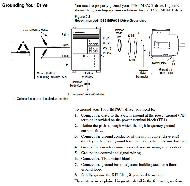
Ground Fault: The motor or cable is short circuited to the ground. Disconnect the motor to measure insulation and check if the cable shielding layer is poorly grounded
Encoder Fault: Encoder wiring error, signal interference check encoder power supply and differential signal, increase shielding layer grounding, reduce PWM frequency
Motor Overload: When the load exceeds the rated torque of the motor and the ambient temperature is too high, reduce the load, check the heat dissipation, and increase the Motor Overload% threshold (not exceeding 125%)
2. Interpretation of LED Status
The frequency converter contains 2 dual color LEDs (DeviceNet and SCAnport), and the status corresponds to the fault type:
Solution to the Meaning of LED Position Status
DeviceNet LED always on, red bus offline/address conflict troubleshooting, node address duplication, check terminal resistance (120 Ω), rewire
Flashing red I/O connection timeout reduces network load, confirms controller online, adjusts RPI (≤ 50ms)
SCANPort LED always on red link fault (no port recognition), disable unsupported Datalink, restart the frequency converter, and check the SCANPort cable
Flashing Orange Compatibility Test Failed Contact Rockwell Technical Support to Confirm HIM/Gateway Compatibility
Technical specifications
Project specification parameters
Input voltage 200-240VAC (± 10%), 380-480VAC (± 10%), 500-600VAC (± 10%), 3-phase 50/60Hz
Output voltage 0-input voltage, 3-phase PWM output, carrier frequency 1-16kHz (adjustable)
Control accuracy without encoder ± 0.5% rated speed, with encoder ± 0.1% rated speed
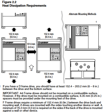
Working environment temperature 0-50 ℃, humidity 0-95%, no condensation, altitude ≤ 1000m (derating required for exceeding 1000m)
Protection level body NEMA 1 (IP20), optional NEMA 4 (IP65)/12 (IP54) (customized casing required)

- ABB
- General Electric
- EMERSON
- Honeywell
- HIMA
- ALSTOM
- Rolls-Royce
- MOTOROLA
- Rockwell
- Siemens
- Woodward
- YOKOGAWA
- FOXBORO
- KOLLMORGEN
- MOOG
- KB
- YAMAHA
- BENDER
- TEKTRONIX
- Westinghouse
- AMAT
- AB
- XYCOM
- Yaskawa
- B&R
- Schneider
- Kongsberg
- NI
- WATLOW
- ProSoft
- SEW
- ADVANCED
- Reliance
- TRICONEX
- METSO
- MAN
- Advantest
- STUDER
- KONGSBERG
- DANAHER MOTION
- Bently
- Galil
- EATON
- MOLEX
- DEIF
- B&W
- ZYGO
- Aerotech
- DANFOSS
- Beijer
- Moxa
- Rexroth
- Johnson
- WAGO
- TOSHIBA
- BMCM
- SMC
- HITACHI
- HIRSCHMANN
- Application field
- XP POWER
- CTI
- TRICON
- STOBER
- Thinklogical
- Horner Automation
- Meggitt
- Fanuc
- Baldor
- SHINKAWA
- Other Brands


