
Allen Bradley 1336 IMPACT AC Inverter
(2) B-H framework (high power)
Fixed method: B-C frame can be installed on rails, D-H frame needs to be fixed with bolts, and reserved heat dissipation space (top/sides ≥ 152.4mm, bottom ≥ 101.6mm).
Wiring requirements: The D-H frame adopts bolt type terminals and requires dedicated wiring terminals (such as T&B COLOR KEYED) ®), The maximum wire diameter supported is 600MCM (253mm ²), and the torque must comply with the specifications (such as 23N · m for the H frame).
Cooling system: F-H frame with forced cooling fan, fan voltage needs to be confirmed (200-240V/380-480V), H frame needs independent air duct, air volume ≥ 2600CFM.
3. Key wiring specifications
Power wiring:
AC input: R/L1, S/L2, T/L3, requiring input fuses/circuit breakers (such as 140-MN-0250 circuit breaker for 380-480V/0.37kW).
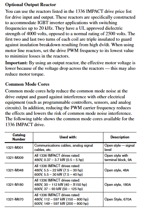
Motor output: U/T1, V/T2, W/T3, cable length must meet the requirements (e.g. maximum 500m at 125Kbps, 100m at 500Kbps), and output reactors need to be added for long distances.
Control wiring:
Analog input: ± 10V input requires differential wiring, and the shielding layer is grounded at one end (TE terminal); 4-20mA input impedance of 130 Ω, maximum load of 750 Ω.
Encoder wiring (L Option board): A/A non, B/B non signal differential access,+12V power supply (maximum 200mA), shielding layer grounded.
Grounding requirements:
The safety grounding (PE terminal) requires copper wire with a wire diameter of ≥ 1.5mm ² (16AWG) and a grounding impedance of ≤ 4 Ω.
The control signal grounding (TE terminal) is independent of the power grounding to avoid common ground interference.
System startup and parameter configuration
1. Preparation before startup
Hardware inspection: Confirm correct wiring (no AC input/output terminals, no short circuits), clean fan/heat sink, and securely install encoder (if any).
Tool preparation: HIM module (default connection to SCANPort 1), digital multimeter (measuring input voltage, within ± 10% of rated value), insulation resistance meter (measuring motor insulation, ≥ 1M Ω).
Parameter recording: Record the frequency converter model, motor nameplate data (power, voltage, current, speed, number of poles), and encoder PPR value for rapid debugging in the future.
2. Quick start process (via HIM)
(1) Power on and HIM operation
After powering on, the HIM displays the startup interface. Press any key to enter "Choose Mode" and select "Start Up".
Quick Motor Tune:
Select 'Enter Nameplate Motor Data' and enter the motor HP, voltage, current, etc Hz、 Speed and number of poles.
If using an encoder, select "Encoder" and enter the PPR value; Choose the braking method (dynamic braking/magnetic flux braking, etc.).
Press the START button to test the direction of motor rotation. If it is reversed, adjust the motor phase sequence; Run self-tuning (inductance, resistance, flux current, inertia test), and display "Tune Complete" after completion.
Config Digital Section:
Configure relay output (such as setting Relay 1 to "At Speed" and threshold to 95% rated speed).
Configure L Option mode (such as mode 5 supporting MOP manual potentiometer control) and stop type (coasting/ramp/current limit stop).
Configure Analog Section:
Link speed reference (e.g. Analog In1 link Speed Ref 1, Scale set to 2.0 to achieve ± 10V corresponding to ± 100% speed).
Configure analog output (such as Analog Out1 linked to Motor Speed, Scale set to 0.5 to achieve ± 100% speed corresponding to ± 5V output).
3. Core parameter description
Parameter classification, key parameter functions, and default values
Motor nameplate Nameplate HP (2) The rated power of the motor should be consistent with the nameplate
Motor Poles (7) motor pole count, default 4 poles
Speed control Speed Ref 1 (29) Main speed reference, default 0rpm
Accel Time 1 (42) acceleration time, default 5.0 seconds
Decel Time 1 (44) Deceleration time, default 5.0 seconds
Feedback and Protection Fdbk Device Type (64) Feedback Device Type, 0=No Encoder, 2=Encoder
Motor Overload% (26) motor overload threshold, default 115%
Communication and Expansion L Option Mode (116) L Option Working Mode, default 1 (disabled)
SP An In1 Select (133) SCANPort analog input selection, default 1 (HIM)
Functional applications and advanced controls
1. Basic control functions
Start stop and speed regulation:
Local control: Use the START/STOP button on HIM to start and stop, and the Up/Down button to adjust the speed; Remote control: Speed regulation through analog input (such as 4-20mA) or SCANPort signal.
Jog Speed 1 (38) is set to 10% rated speed, triggering Jog input to achieve jog control.
Braking control:
Dynamic braking: An external braking resistor is required, with Bus/Brake Options (13) set to bit10=1 and Regen Power Lim (76) set to 50% (adjusted according to the resistor capacity).
DC Braking: The DC Brake Current (79) is set to 30% of the rated current, and the DC Brake Time (80) is set to 2 seconds, suitable for rapid shutdown.
2. Advanced functional applications
(1) Speed Profiling
Function: Implement multi-stage speed control through 16 programmable steps, supporting switching between time, encoder counting, and digital input trigger steps.
- OMRON
- ABB
- General Electric
- EMERSON
- Honeywell
- HIMA
- ALSTOM
- Rolls-Royce
- MOTOROLA
- Rockwell
- Siemens
- Woodward
- YOKOGAWA
- FOXBORO
- KOLLMORGEN
- MOOG
- KB
- YAMAHA
- BENDER
- TEKTRONIX
- Westinghouse
- AMAT
- AB
- XYCOM
- Yaskawa
- B&R
- Schneider
- KONGSBERG
- NI
- WATLOW
- ProSoft
- SEW
- ADVANCED
- Reliance
- TRICONEX
- METSO
- MAN
- Advantest
- STUDER
- DANAHER MOTION
- Bently
- Galil
- EATON
- MOLEX
- DEIF
- B&W
- ZYGO
- Aerotech
- DANFOSS
- Beijer
- Moxa
- Rexroth
- Johnson
- WAGO
- TOSHIBA
- BMCM
- SMC
- HITACHI
- HIRSCHMANN
- Application field
- XP POWER
- CTI
- TRICON
- STOBER
- Thinklogical
- Horner Automation
- Meggitt
- Fanuc
- Baldor
- SHINKAWA
- Other Brands
- UniOP
- KUKA
- Iba
- Beckhoff
-
 Basler DECS-200-2L Digital Excitation Control
 -
 Basler BE1-47N Voltage Phase Sequence Relay
 -
 Basler AEC63-7 Analog Excitation Controller 220-277V
 -
 Basler BE1-50/51B-107 Overcurrent Relay
 -
 Basler Electric BE1‑32R BE1‑E1P‑BON0F Protective Relay
 -
 Basler BE1-25 Solid State Time Overcurrent Relay M1EA6PA5S1F
 -
 Basler MVC 232 Manual Voltage Control Module 90 37000 103 60VAC 55VDC
 -
 Basler RAL6144-16GM Racer GigE Line Scan Camera
 -
 Basler SSR 63-12 Static Voltage Regulator
 -
 Basler BE1-51A Overcurrent Relay
 -
 Basler BE1-87T Solid State Protective Relay
 -
 Basler SR4A2B01B3A Static Voltage Regulator
 -
 Basler SSR 32-12 Static Voltage Regulator
 -
 Basler TRR00696 Transformer 1KVA 115V
 -
 Basler DECS-100-B15 AVR Replacement
 -
Basler BE1-27 Under-Voltage Relay
-
 Basler ACA2000-50GM Interface Module
 -
 Basler AEC63-7 Analog Excitation Controller
 -
 Basler PRS 250 Veri-Sync Relay
 -
 Basler SR4A-2B15B3A Static Voltage Regulator
 -
Basler BE1-32R Power Relay
-
Basler SR8A-2B06B3E Static Voltage Regulator
-
Basler BE1-81 O/U Frequency Relay
-
 Basler BE1-51A-K2E-W6M-B1N0F Overcurrent Relay
 -
Basler BE1-851 Overcurrent Relay G3A1S1 – 48-125V AC/DC
-
 Basler BEI-51 Overcurrent Relay – NSN 5945-01-293-2363
 -
Basler Electric L301KC Protective Relay – L301KC
-
 Basler DECS-100-B15 Automatic Voltage Regulator – Generator AVR
 -
 Basler SR4A-2B15B3A Static Voltage Regulator – SR4A2B15B3A
 -
 Basler UF 312 Under Frequency Protective Module – 9094700100
 -
Basler Electric MVC 232 Manual Control Module – 60VAC 55VDC 20A
-
Basler PRS 250 Veri-Sync Relay – Generator Synchronizing Relay
-
 Basler DECS-100-A05 Digital Regulator Review
 -
 Basler AEM-2020 Analog Expansion Module Specs
 -
 Basler DECS-100-B15 Digital Excitation Specs
 -
Basler Electric 9125600106 Regulator Component
-
Basler BE1-51A-K1E-W6M-B1N0F Overcurrent Relay
-
 Basler MVC-301 MVC 300 Excitation Controller
 -
 Basler SSR 32-12 Static Voltage Regulator
 -
 Basler 9-2849-00-101 Control Module
 -
Basler BE1-51A Overcurrent Relay
-
 Basler BE1-51/27R Overcurrent Relay
 -
 Basler BE1-51 Overcurrent Relay
 -
 Basler SR8A-2B15B3A Static Voltage Regulator
 -
 Basler BE32965001 Transformer and Timer Board
 -
 Basler 9174700100 EL200-7 Excitation Limiter
 -
 Basler BE2000E AVR Voltage Regulator
 -
Basler BE1-87G Differential Relay
-
 Basler BE21834001 Generator Control Module
 -
Basler DECS-100-B15 AVR
-
 Basler D90 96801 100 PCB Card
 -
 Basler XR2002F Voltage Regulator (110 VAC, 48-480 Hz)
 -
 Basler SR8A-2B14B3A Regulator
 -
 Basler 9561500100 Module
 -
 Basler DECS-400 BE1-11 System
 -
 Basler DECS-100-B15 Excitation Control
 -
 Basler SCP 210 Frequency Controller
 -
Basler SR4A-2B15B3A Static Voltage Regulator
-
Basler BE1-32R Power Relay
-
 Basler PIA2400-17GM Power Interface Adapter
 -
 Basler MVC 232 Manual Voltage Control Module
 -
 Basler SSR 32-12 Static Voltage Regulator
 -
Basler 5MW AVR Generator Voltage Regulator
-
 Basler VR63-4B Voltage Regulator
 -
Basler DECS-100-A05 AVR for Engine Generator
-
Basler DECS-100-B15 Automatic Voltage Regulator
-
Basler BE1-32R Directional Power Relay
-
Basler BE1-87B Differential Relay
-
 Basler UFOV 260A Protective Module
 -
 Basler 9-2614-02-100 PCB Rev M
 -
Basler DECS-100-B15 Digital AVR
-
 Basler 9284900103 PS DECS-400N
 -
 Basler D4N3H1U Intertie Protection
 -
 Basler DECS-100-B15 A15 AVR
 -
 Basler KR4F Voltage Regulator
 -
 Basler BE26434 T14 Transformer
 -
 Basler SR8A-2B15B3A Regulator
 -
 Westinghouse 774B472A12 AR Relay
 -
Basler DECS-100-B15 AVR
-
Basler XR2002F Regulator 110V
-
Basler SR125-E Static Regulator
-
Basler SSR 125-12 Regulator
-
Basler MOC2599 Motor Pot
-
 Basler BE1-DFPR Feeder Relay
 -
 Basler CBS 305 Current Boost
 -
Basler BE1-25 AutoSync
-
Basler MVC 300 Voltage Control
-
 Basler BE3-25A AutoSync
 -
 Basler KR7FF Static Regulator
 -
Basler 90-49000-100 Regulator
-
 Basler 880 kVA Dry Type Transformer Specs
 -
Basler Electric BE1-25 Sync-Check Relay Specs
-
 Basler SSR 125-12 Voltage Regulator Specs
 -
 Basler Electric BE1-851 Overcurrent Relay Review
 -
Basler Electric 149D930G02 Control Sub-Assembly
-
 Basler Electric BE1-81O/UT Frequency Relay Specs
 -
 Basler Electric BE1-51/27C Overcurrent Relay
 -
 Basler Electric 149D956G02 Industrial Component
 -
Basler Electric BE1-51A Overcurrent Relay Specs
-
 Basler Electric BE1-40Q Loss of Excitation Relay
 -
Basler DECS-200 Excitation Control System
-
 Basler DECS-200 Voltage Regulator 56-277V AC / 125V DC
 -
Basler BE1-87T Transformer Differential Relay
-
 Basler RDP-110-S1 Protection Relay
 -
 Basler BE1-700V Digital Protective Relay
 -
 Basler BE1-951 Overcurrent Protection System
 -
 Basler DECS-300 Digital Excitation Control
 -
 Basler DECS-200 Digital Excitation Control
 -
 Basler DECS-200-1C Excitation Control System
 -
Basler DECS-200-1L Digital Excitation Control
-
 Basler Electric BE1-GPS Generator Protection System
 -
Basler Electric DECS-200-1C Digital Excitation Controller
-
 Basler Electric DECS125-15 Excitation Control with Power Module
 -
Basler Electric BE1-87G Differential Relay
-
 Basler Electric BE1-11 Protection System I5A3M2P2N0EA00
 -
Basler Electric DECS-200-1C Excitation Control System
-
Basler Electric BE1-11g Generator Protection Relay
-
Basler Electric DECS 125-15-B2C1 V2.0.9 Excitation Control
-
Basler Electric BE1-81O/UT3ED1JA7N2F Frequency Relay
-
Basler Electric BE1-81O/UT3EE1YB7N1F Frequency Relay
-
 Basler Electric DECS-200-1L Digital Excitation Control System
 -
Basler DECS125-15-B2C1 Excitation Control
-
 Basler 9507900205 SSR Retrofit Voltage Regulator
 -
 Basler BE2000E Digital Voltage Regulator
 -
 Basler BE1-GPS Generator Protection System
 -
Basler DECS-250-CN1CN1N Digital Excitation Control
-
 Basler DGC-2020 Genset Controller
 -
Basler BE1-81O UT3ED1LA7N0F Frequency Relay (Variant)


