
Allen Bradley 1336 IMPACT AC Inverter
Allen Bradley 1336 IMPACT AC Inverter
Product Overview and Core Features
1. Product positioning and applicable scenarios
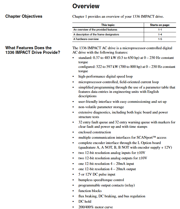
1336 IMPACT frequency converter is a microprocessor based field oriented control (FOC) AC frequency converter using Force technologies ™ Technology, focusing on low-cost independent applications, suitable for scenarios such as machine tools, production lines, and material handling that require precise speed regulation, supports speed and torque control of asynchronous motors, and is compatible with multiple feedback devices and communication protocols.
2. Core standard features
Performance and Control:
High precision digital speed loop and current loop, supporting 0-250Hz constant torque output, some configurations can achieve 400% motor current (short-term overload).
Supports multiple braking methods: dynamic braking, DC braking, magnetic flux braking, and bus voltage regulation, adapting to different load deceleration requirements.
Feedback and Interface:
Standard configuration includes 2 ± 10V analog inputs, 2 ± 10V analog outputs, and 1 4-20mA input/output. The 12 bit resolution ensures signal accuracy.
Support encoder feedback (requires L Option board), compatible with 12V/5V differential output encoder, up to 100kHz pulse input, achieving high-precision speed/position control.
Protection and reliability:
Built in motor overload protection (I ² T), inverter overload protection, overcurrent, overvoltage, undervoltage, ground fault, overheating and other multiple protections.
32 fault queues and 32 warning queues, with timestamps and fault markers for easy problem tracing; Non volatile memory (EE) stores parameters and configurations without loss during power outages.
Communication and Expansion:
Supports SCANPort communication and can connect to HIM (Human Interface Module), GPT (Graphics Programming Terminal), and 1203 series gateway modules (such as DeviceNet, RS-232/485).
Optional L Option board extension control input, supports TTL/24V AC/DC/115V AC interfaces, and some models come with encoder feedback interfaces.
Model Interpretation and Framework Classification
1. Model coding rules (taking 1336E-AQF05-AA-EN as an example)
Explanation of the meaning of digit codes
1-4 Position 1336E Product Series 1336 IMPACT AC Inverter
Position 5-6 AQ voltage level AQ=200-240VAC/310VDC; BR=380-480VAC/513-620VDC; CW=500-600VAC/775VDC
The rated power of F05 in positions 7-9 is 0.37kW (0.5HP); F07=0.56kW (0.75HP); F10=0.75kW (1HP), Repeat this process until 800C=597kW (800HP)
AA protection level AA=NEMA 1 (IP20) for positions 10-11; AE=NEMA 1 (IP20)/EMC (0.37-45kW dedicated); AF=NEMA 4 (IP65); AJ=NEMA 12 (IP54)
The 12th and 13th digits of EN language are English/English; FR=English/French; ES=English/Spanish; DE=English/German, etc
Subsequent mod options include HIM type (such as HA1 with analog potentiometer), communication module (such as GM5=DeviceNet), and L Option board (such as L8E=24V AC/DC+encoder)
2. Frame classification and power correspondence
The framework is divided by size and power, and the installation and wiring requirements for different frameworks are different. The core correspondence is as follows:
Framework Model 200-240V Power Range 380-480V Power Range 500-600V Power Range Key Features
A1 0.37-0.75kW (0.5-1HP) 0.37-1.2kW (0.5-1.5HP) - miniaturization, suitable for light loads
A2 1.2-1.5kW (1.5-2HP) 1.5-2.2kW (2-3HP) - Compact, supporting basic analog control
A3 2.2-3.7kW (3-5HP) 3.7kW (5HP) - Medium load, optional encoder feedback
A4-5.5-7.5kW (7.5-10HP) 0.75-7.5kW (1-10HP) with cooling fan, supporting dynamic braking
B 5.5-11kW (7.5-15HP) 15-22kW (20-30HP) 11-15kW (15-20HP) modular design, supporting multiple communication interfaces
C-H 30-75kW (40-100HP) 45-597kW (60-800HP) high power, requiring external reactors, H frame with independent cooling system
Installation and wiring specifications
1. General safety requirements
Static protection: The module contains ESD sensitive components, and a grounding wristband should be worn during operation. Refer to Rockwell document 8000-4.5.2 "Guidelines for Preventing Static Damage".
Power off operation: Before installation, all power sources of the frequency converter (including AC input, DC bus, control power) must be disconnected to avoid electric shock or component damage.
Cable requirements: Power cables must comply with NEC/VDE standards, and it is recommended to use shielded twisted pair cables (such as Belden 8760) for control cables to avoid parallel laying with high-power cables and reduce interference.
2. Key points for exclusive installation of the framework
(1) A1-A4 frame (low power)
Rail installation: Suitable for 35 × 7.5mm DIN rails, with hooks inserted and locked by rotation. The grounding resistance should be ≤ 2 Ω (detected through the metal shell of the RS-232 port).
Wiring terminal: TB1 is the power terminal (R/L1, S/L2, T/L3 input; U/T1, V/T2, W/T3 outputs), TB4/TB7/TB10 are control terminals, supporting analog I/O, pulse input, and relay output.
Input protection: Users need to provide their own fuses. For example, models with 200-240V/0.37kW require 6A Class CC fuses (North America) or 6A gG fuses (Europe).
- OMRON
- ABB
- General Electric
- EMERSON
- Honeywell
- HIMA
- ALSTOM
- Rolls-Royce
- MOTOROLA
- Rockwell
- Siemens
- Woodward
- YOKOGAWA
- FOXBORO
- KOLLMORGEN
- MOOG
- KB
- YAMAHA
- BENDER
- TEKTRONIX
- Westinghouse
- AMAT
- AB
- XYCOM
- Yaskawa
- B&R
- Schneider
- KONGSBERG
- NI
- WATLOW
- ProSoft
- SEW
- ADVANCED
- Reliance
- TRICONEX
- METSO
- MAN
- Advantest
- STUDER
- DANAHER MOTION
- Bently
- Galil
- EATON
- MOLEX
- DEIF
- B&W
- ZYGO
- Aerotech
- DANFOSS
- Beijer
- Moxa
- Rexroth
- Johnson
- WAGO
- TOSHIBA
- BMCM
- SMC
- HITACHI
- HIRSCHMANN
- Application field
- XP POWER
- CTI
- TRICON
- STOBER
- Thinklogical
- Horner Automation
- Meggitt
- Fanuc
- Baldor
- SHINKAWA
- Other Brands
- UniOP
- KUKA
- Iba
- Beckhoff
-
 Basler DECS-200-2L Digital Excitation Control
 -
 Basler BE1-47N Voltage Phase Sequence Relay
 -
 Basler AEC63-7 Analog Excitation Controller 220-277V
 -
 Basler BE1-50/51B-107 Overcurrent Relay
 -
 Basler Electric BE1‑32R BE1‑E1P‑BON0F Protective Relay
 -
 Basler BE1-25 Solid State Time Overcurrent Relay M1EA6PA5S1F
 -
 Basler MVC 232 Manual Voltage Control Module 90 37000 103 60VAC 55VDC
 -
 Basler RAL6144-16GM Racer GigE Line Scan Camera
 -
 Basler SSR 63-12 Static Voltage Regulator
 -
 Basler BE1-51A Overcurrent Relay
 -
 Basler BE1-87T Solid State Protective Relay
 -
 Basler SR4A2B01B3A Static Voltage Regulator
 -
 Basler SSR 32-12 Static Voltage Regulator
 -
 Basler TRR00696 Transformer 1KVA 115V
 -
 Basler DECS-100-B15 AVR Replacement
 -
Basler BE1-27 Under-Voltage Relay
-
 Basler ACA2000-50GM Interface Module
 -
 Basler AEC63-7 Analog Excitation Controller
 -
 Basler PRS 250 Veri-Sync Relay
 -
 Basler SR4A-2B15B3A Static Voltage Regulator
 -
Basler BE1-32R Power Relay
-
Basler SR8A-2B06B3E Static Voltage Regulator
-
Basler BE1-81 O/U Frequency Relay
-
 Basler BE1-51A-K2E-W6M-B1N0F Overcurrent Relay
 -
Basler BE1-851 Overcurrent Relay G3A1S1 – 48-125V AC/DC
-
 Basler BEI-51 Overcurrent Relay – NSN 5945-01-293-2363
 -
Basler Electric L301KC Protective Relay – L301KC
-
 Basler DECS-100-B15 Automatic Voltage Regulator – Generator AVR
 -
 Basler SR4A-2B15B3A Static Voltage Regulator – SR4A2B15B3A
 -
 Basler UF 312 Under Frequency Protective Module – 9094700100
 -
Basler Electric MVC 232 Manual Control Module – 60VAC 55VDC 20A
-
Basler PRS 250 Veri-Sync Relay – Generator Synchronizing Relay
-
 Basler DECS-100-A05 Digital Regulator Review
 -
 Basler AEM-2020 Analog Expansion Module Specs
 -
 Basler DECS-100-B15 Digital Excitation Specs
 -
Basler Electric 9125600106 Regulator Component
-
Basler BE1-51A-K1E-W6M-B1N0F Overcurrent Relay
-
 Basler MVC-301 MVC 300 Excitation Controller
 -
 Basler SSR 32-12 Static Voltage Regulator
 -
 Basler 9-2849-00-101 Control Module
 -
Basler BE1-51A Overcurrent Relay
-
 Basler BE1-51/27R Overcurrent Relay
 -
 Basler BE1-51 Overcurrent Relay
 -
 Basler SR8A-2B15B3A Static Voltage Regulator
 -
 Basler BE32965001 Transformer and Timer Board
 -
 Basler 9174700100 EL200-7 Excitation Limiter
 -
 Basler BE2000E AVR Voltage Regulator
 -
Basler BE1-87G Differential Relay
-
 Basler BE21834001 Generator Control Module
 -
Basler DECS-100-B15 AVR
-
 Basler D90 96801 100 PCB Card
 -
 Basler XR2002F Voltage Regulator (110 VAC, 48-480 Hz)
 -
 Basler SR8A-2B14B3A Regulator
 -
 Basler 9561500100 Module
 -
 Basler DECS-400 BE1-11 System
 -
 Basler DECS-100-B15 Excitation Control
 -
 Basler SCP 210 Frequency Controller
 -
Basler SR4A-2B15B3A Static Voltage Regulator
-
Basler BE1-32R Power Relay
-
 Basler PIA2400-17GM Power Interface Adapter
 -
 Basler MVC 232 Manual Voltage Control Module
 -
 Basler SSR 32-12 Static Voltage Regulator
 -
Basler 5MW AVR Generator Voltage Regulator
-
 Basler VR63-4B Voltage Regulator
 -
Basler DECS-100-A05 AVR for Engine Generator
-
Basler DECS-100-B15 Automatic Voltage Regulator
-
Basler BE1-32R Directional Power Relay
-
Basler BE1-87B Differential Relay
-
 Basler UFOV 260A Protective Module
 -
 Basler 9-2614-02-100 PCB Rev M
 -
Basler DECS-100-B15 Digital AVR
-
 Basler 9284900103 PS DECS-400N
 -
 Basler D4N3H1U Intertie Protection
 -
 Basler DECS-100-B15 A15 AVR
 -
 Basler KR4F Voltage Regulator
 -
 Basler BE26434 T14 Transformer
 -
 Basler SR8A-2B15B3A Regulator
 -
 Westinghouse 774B472A12 AR Relay
 -
Basler DECS-100-B15 AVR
-
Basler XR2002F Regulator 110V
-
Basler SR125-E Static Regulator
-
Basler SSR 125-12 Regulator
-
Basler MOC2599 Motor Pot
-
 Basler BE1-DFPR Feeder Relay
 -
 Basler CBS 305 Current Boost
 -
Basler BE1-25 AutoSync
-
Basler MVC 300 Voltage Control
-
 Basler BE3-25A AutoSync
 -
 Basler KR7FF Static Regulator
 -
Basler 90-49000-100 Regulator
-
 Basler 880 kVA Dry Type Transformer Specs
 -
Basler Electric BE1-25 Sync-Check Relay Specs
-
 Basler SSR 125-12 Voltage Regulator Specs
 -
 Basler Electric BE1-851 Overcurrent Relay Review
 -
Basler Electric 149D930G02 Control Sub-Assembly
-
 Basler Electric BE1-81O/UT Frequency Relay Specs
 -
 Basler Electric BE1-51/27C Overcurrent Relay
 -
 Basler Electric 149D956G02 Industrial Component
 -
Basler Electric BE1-51A Overcurrent Relay Specs
-
 Basler Electric BE1-40Q Loss of Excitation Relay
 -
Basler DECS-200 Excitation Control System
-
 Basler DECS-200 Voltage Regulator 56-277V AC / 125V DC
 -
Basler BE1-87T Transformer Differential Relay
-
 Basler RDP-110-S1 Protection Relay
 -
 Basler BE1-700V Digital Protective Relay
 -
 Basler BE1-951 Overcurrent Protection System
 -
 Basler DECS-300 Digital Excitation Control
 -
 Basler DECS-200 Digital Excitation Control
 -
 Basler DECS-200-1C Excitation Control System
 -
Basler DECS-200-1L Digital Excitation Control
-
 Basler Electric BE1-GPS Generator Protection System
 -
Basler Electric DECS-200-1C Digital Excitation Controller
-
 Basler Electric DECS125-15 Excitation Control with Power Module
 -
Basler Electric BE1-87G Differential Relay
-
 Basler Electric BE1-11 Protection System I5A3M2P2N0EA00
 -
Basler Electric DECS-200-1C Excitation Control System
-
Basler Electric BE1-11g Generator Protection Relay
-
Basler Electric DECS 125-15-B2C1 V2.0.9 Excitation Control
-
Basler Electric BE1-81O/UT3ED1JA7N2F Frequency Relay
-
Basler Electric BE1-81O/UT3EE1YB7N1F Frequency Relay
-
 Basler Electric DECS-200-1L Digital Excitation Control System
 -
Basler DECS125-15-B2C1 Excitation Control
-
 Basler 9507900205 SSR Retrofit Voltage Regulator
 -
 Basler BE2000E Digital Voltage Regulator
 -
 Basler BE1-GPS Generator Protection System
 -
Basler DECS-250-CN1CN1N Digital Excitation Control
-
 Basler DGC-2020 Genset Controller
 -
Basler BE1-81O UT3ED1LA7N0F Frequency Relay (Variant)


