
Allen Bradley 1391-DES series digital AC servo drive
Allen Bradley 1391-DES series digital AC servo drive
Basic information of the driver
Product positioning and functionality
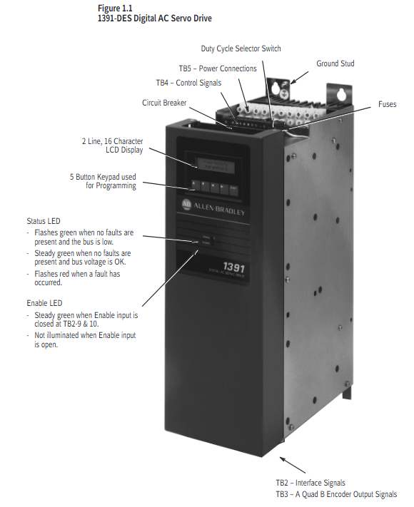
1391-DES is a digital programmable single axis AC servo drive that is compatible with Allen Bradley 1326 series AC servo motors. It is mainly used in closed-loop positioning systems such as machine tools and automation equipment (such as IMC S-class and MAX controllers), and supports speed and torque control modes.
Core advantage: It can enable the 1326 motor to exceed the rated speed by 33% -50%, improving equipment accuracy and production efficiency; Equipped with encoder output (AQB), providing position feedback signals of 256/512/1024/2048 lines per revolution, compatible with positioning controllers.
Model and Key Parameters
Model classification: Divided by continuous current, it is 1391-DES15 (15A), 1391-DES22 (22.5A), and 1391-DES45 (45A), all of which have the same physical dimensions but different electrical parameters.
Core electrical parameters: rated DC bus voltage of 300V DC, peak current twice the continuous current (such as DES45 peak 90A), modulation frequency of 2500Hz ± 10%, speed regulation accuracy of 0-0.05% (under 95% load variation), operating temperature of 0-60 ° C, no need to reduce capacity at altitude ≤ 1000 meters.
Standard configuration and optional features
Standard functions: Input transient voltage protection, built-in circuit breaker, DC bus shunt regulator (dissipating regenerative energy), 2-row LCD display and programming panel, torque feedforward differential input, microprocessor control board (easy to disassemble and troubleshoot).
Optional functions: Contactor auxiliary switch (for motor braking control or status indication), external shunt resistor (suitable for high regenerative energy scenarios, such as optional 386W external resistor for 22.5A drivers), speed/current monitoring output, anti backlash control, linear acceleration/deceleration module (CR-APG-001, supports 4 preset speeds).
Working principle
Core Circuit and Energy Processing
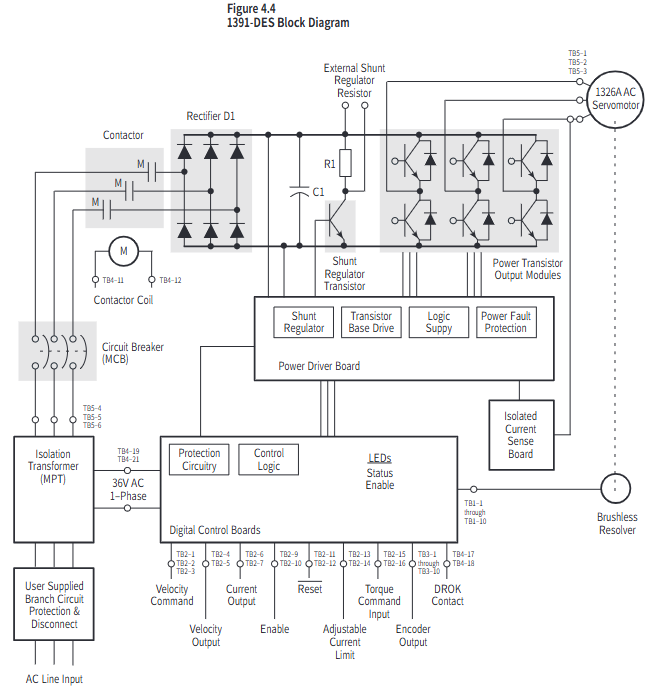
Power Conversion: Convert 3-phase 50/60Hz AC power into 300V DC bus voltage through a rectifier bridge, and then output variable voltage AC power through a PWM inverter to control motor speed and torque.
Regenerative braking: The regenerative energy generated during motor deceleration will increase the DC bus voltage. When the shunt regulator detects that the voltage exceeds the threshold (386.4V DC), it triggers the chopper transistor to conduct, converting the energy into thermal energy through the braking resistor to avoid bus overvoltage tripping (overvoltage protection threshold 405V DC).
control logic
Closed loop control: By using a motor resolver (rotary transformer) to provide feedback on the rotor position, combined with speed/torque commands, and adjusting through current and speed loops, precise control is achieved; The current loop adopts analog control, and the speed command supports ± 10V DC analog input.
Start stop mode: includes three modes: dynamic braking (bus discharge braking when the contactor is disconnected), regenerative braking (reverse torque braking when the enable signal is disconnected), and free parking (driver disconnection output in case of fault, motor inertia parking).
Installation and wiring
Installation requirements
Environment: It needs to be installed in a closed cabinet, and ventilation should be filtered/cooled to avoid oil mist, dust, and corrosive gases; Vertical installation, distance between single driver and motor ≤ 3m, distance between main driver and frequency converter ≤ 3m when multiple drivers, distance between sub drivers and main drivers ≤ 1.5m, equipment spacing ≥ 304.8mm (to ensure heat dissipation).
Grounding: The driver housing needs to be reliably grounded, and signal grounding (such as resolver, control signal) should use a "star grounding" to avoid introducing noise into the grounding loop.
Wiring specifications
Power wiring: The motor power lines (TB5-1~3) and input power lines (TB5-4~6) need to be twisted pair, separately threaded through pipes, and the wire diameter should refer to the manual (such as 8AWG/6mm ² for DES45); The external shunt resistors (TB5-8~10) need to be matched according to the model (for example, a 45A driver requires an external 5 Ω resistor).
Signal wiring: Control signals such as speed command (TB2-1~2), enable signal (TB2-9~10), reset signal (TB2-11), etc. require 18AWG twisted pair cable with a distance of ≥ 304.8mm from the power line; resolver wiring (TB1-1~10) requires shielded wire with the shielding layer grounded at one end.
Switch and jumper settings
Split regulator duty cycle switch (SW1): adjusts the overheat protection threshold of the braking resistor, and different drivers correspond to different gears (such as setting it to "F" gear when DES22 is equipped with an external resistor).
AQB encoder output switch (S1): Select the number of output lines (256/512/1024/2048), which should match the parameters of the positioning controller (such as halving the number of lines for IMC classic controllers).
Programming and Debugging
Parameter hierarchy and operation
- OMRON
- ABB
- General Electric
- EMERSON
- Honeywell
- HIMA
- ALSTOM
- Rolls-Royce
- MOTOROLA
- Rockwell
- Siemens
- Woodward
- YOKOGAWA
- FOXBORO
- KOLLMORGEN
- MOOG
- KB
- YAMAHA
- BENDER
- TEKTRONIX
- Westinghouse
- AMAT
- AB
- XYCOM
- Yaskawa
- B&R
- Schneider
- KONGSBERG
- NI
- WATLOW
- ProSoft
- SEW
- ADVANCED
- Reliance
- TRICONEX
- METSO
- MAN
- Advantest
- STUDER
- DANAHER MOTION
- Bently
- Galil
- EATON
- MOLEX
- DEIF
- B&W
- ZYGO
- Aerotech
- DANFOSS
- Beijer
- Moxa
- Rexroth
- Johnson
- WAGO
- TOSHIBA
- BMCM
- SMC
- HITACHI
- HIRSCHMANN
- Application field
- XP POWER
- CTI
- TRICON
- STOBER
- Thinklogical
- Horner Automation
- Meggitt
- Fanuc
- Baldor
- SHINKAWA
- Other Brands
- UniOP
- KUKA
- Iba
- Beckhoff
-
 Basler DECS-200-2L Digital Excitation Control
 -
 Basler BE1-47N Voltage Phase Sequence Relay
 -
 Basler AEC63-7 Analog Excitation Controller 220-277V
 -
 Basler BE1-50/51B-107 Overcurrent Relay
 -
 Basler Electric BE1‑32R BE1‑E1P‑BON0F Protective Relay
 -
 Basler BE1-25 Solid State Time Overcurrent Relay M1EA6PA5S1F
 -
 Basler MVC 232 Manual Voltage Control Module 90 37000 103 60VAC 55VDC
 -
 Basler RAL6144-16GM Racer GigE Line Scan Camera
 -
 Basler SSR 63-12 Static Voltage Regulator
 -
 Basler BE1-51A Overcurrent Relay
 -
 Basler BE1-87T Solid State Protective Relay
 -
 Basler SR4A2B01B3A Static Voltage Regulator
 -
 Basler SSR 32-12 Static Voltage Regulator
 -
 Basler TRR00696 Transformer 1KVA 115V
 -
 Basler DECS-100-B15 AVR Replacement
 -
Basler BE1-27 Under-Voltage Relay
-
 Basler ACA2000-50GM Interface Module
 -
 Basler AEC63-7 Analog Excitation Controller
 -
 Basler PRS 250 Veri-Sync Relay
 -
 Basler SR4A-2B15B3A Static Voltage Regulator
 -
Basler BE1-32R Power Relay
-
Basler SR8A-2B06B3E Static Voltage Regulator
-
Basler BE1-81 O/U Frequency Relay
-
 Basler BE1-51A-K2E-W6M-B1N0F Overcurrent Relay
 -
Basler BE1-851 Overcurrent Relay G3A1S1 – 48-125V AC/DC
-
 Basler BEI-51 Overcurrent Relay – NSN 5945-01-293-2363
 -
Basler Electric L301KC Protective Relay – L301KC
-
 Basler DECS-100-B15 Automatic Voltage Regulator – Generator AVR
 -
 Basler SR4A-2B15B3A Static Voltage Regulator – SR4A2B15B3A
 -
 Basler UF 312 Under Frequency Protective Module – 9094700100
 -
Basler Electric MVC 232 Manual Control Module – 60VAC 55VDC 20A
-
Basler PRS 250 Veri-Sync Relay – Generator Synchronizing Relay
-
 Basler DECS-100-A05 Digital Regulator Review
 -
 Basler AEM-2020 Analog Expansion Module Specs
 -
 Basler DECS-100-B15 Digital Excitation Specs
 -
Basler Electric 9125600106 Regulator Component
-
Basler BE1-51A-K1E-W6M-B1N0F Overcurrent Relay
-
 Basler MVC-301 MVC 300 Excitation Controller
 -
 Basler SSR 32-12 Static Voltage Regulator
 -
 Basler 9-2849-00-101 Control Module
 -
Basler BE1-51A Overcurrent Relay
-
 Basler BE1-51/27R Overcurrent Relay
 -
 Basler BE1-51 Overcurrent Relay
 -
 Basler SR8A-2B15B3A Static Voltage Regulator
 -
 Basler BE32965001 Transformer and Timer Board
 -
 Basler 9174700100 EL200-7 Excitation Limiter
 -
 Basler BE2000E AVR Voltage Regulator
 -
Basler BE1-87G Differential Relay
-
 Basler BE21834001 Generator Control Module
 -
Basler DECS-100-B15 AVR
-
 Basler D90 96801 100 PCB Card
 -
 Basler XR2002F Voltage Regulator (110 VAC, 48-480 Hz)
 -
 Basler SR8A-2B14B3A Regulator
 -
 Basler 9561500100 Module
 -
 Basler DECS-400 BE1-11 System
 -
 Basler DECS-100-B15 Excitation Control
 -
 Basler SCP 210 Frequency Controller
 -
Basler SR4A-2B15B3A Static Voltage Regulator
-
Basler BE1-32R Power Relay
-
 Basler PIA2400-17GM Power Interface Adapter
 -
 Basler MVC 232 Manual Voltage Control Module
 -
 Basler SSR 32-12 Static Voltage Regulator
 -
Basler 5MW AVR Generator Voltage Regulator
-
 Basler VR63-4B Voltage Regulator
 -
Basler DECS-100-A05 AVR for Engine Generator
-
Basler DECS-100-B15 Automatic Voltage Regulator
-
Basler BE1-32R Directional Power Relay
-
Basler BE1-87B Differential Relay
-
 Basler UFOV 260A Protective Module
 -
 Basler 9-2614-02-100 PCB Rev M
 -
Basler DECS-100-B15 Digital AVR
-
 Basler 9284900103 PS DECS-400N
 -
 Basler D4N3H1U Intertie Protection
 -
 Basler DECS-100-B15 A15 AVR
 -
 Basler KR4F Voltage Regulator
 -
 Basler BE26434 T14 Transformer
 -
 Basler SR8A-2B15B3A Regulator
 -
 Westinghouse 774B472A12 AR Relay
 -
Basler DECS-100-B15 AVR
-
Basler XR2002F Regulator 110V
-
Basler SR125-E Static Regulator
-
Basler SSR 125-12 Regulator
-
Basler MOC2599 Motor Pot
-
 Basler BE1-DFPR Feeder Relay
 -
 Basler CBS 305 Current Boost
 -
Basler BE1-25 AutoSync
-
Basler MVC 300 Voltage Control
-
 Basler BE3-25A AutoSync
 -
 Basler KR7FF Static Regulator
 -
Basler 90-49000-100 Regulator
-
 Basler 880 kVA Dry Type Transformer Specs
 -
Basler Electric BE1-25 Sync-Check Relay Specs
-
 Basler SSR 125-12 Voltage Regulator Specs
 -
 Basler Electric BE1-851 Overcurrent Relay Review
 -
Basler Electric 149D930G02 Control Sub-Assembly
-
 Basler Electric BE1-81O/UT Frequency Relay Specs
 -
 Basler Electric BE1-51/27C Overcurrent Relay
 -
 Basler Electric 149D956G02 Industrial Component
 -
Basler Electric BE1-51A Overcurrent Relay Specs
-
 Basler Electric BE1-40Q Loss of Excitation Relay
 -
Basler DECS-200 Excitation Control System
-
 Basler DECS-200 Voltage Regulator 56-277V AC / 125V DC
 -
Basler BE1-87T Transformer Differential Relay
-
 Basler RDP-110-S1 Protection Relay
 -
 Basler BE1-700V Digital Protective Relay
 -
 Basler BE1-951 Overcurrent Protection System
 -
 Basler DECS-300 Digital Excitation Control
 -
 Basler DECS-200 Digital Excitation Control
 -
 Basler DECS-200-1C Excitation Control System
 -
Basler DECS-200-1L Digital Excitation Control
-
 Basler Electric BE1-GPS Generator Protection System
 -
Basler Electric DECS-200-1C Digital Excitation Controller
-
 Basler Electric DECS125-15 Excitation Control with Power Module
 -
Basler Electric BE1-87G Differential Relay
-
 Basler Electric BE1-11 Protection System I5A3M2P2N0EA00
 -
Basler Electric DECS-200-1C Excitation Control System
-
Basler Electric BE1-11g Generator Protection Relay
-
Basler Electric DECS 125-15-B2C1 V2.0.9 Excitation Control
-
Basler Electric BE1-81O/UT3ED1JA7N2F Frequency Relay
-
Basler Electric BE1-81O/UT3EE1YB7N1F Frequency Relay
-
 Basler Electric DECS-200-1L Digital Excitation Control System
 -
Basler DECS125-15-B2C1 Excitation Control
-
 Basler 9507900205 SSR Retrofit Voltage Regulator
 -
 Basler BE2000E Digital Voltage Regulator
 -
 Basler BE1-GPS Generator Protection System
 -
Basler DECS-250-CN1CN1N Digital Excitation Control
-
 Basler DGC-2020 Genset Controller
 -
Basler BE1-81O UT3ED1LA7N0F Frequency Relay (Variant)


