
Allen Bradley 150 Series SMC Dialog Plus Controller
Allen Bradley 150 Series SMC Dialog Plus Controller
Core framework and scope of application
The document is divided into 10 core chapters and 4 appendices, with a clear and progressive structure based on the logic of "operation process+technical details". The applicable product is SMC Dialog Plus controller (Bulletin 150), which supports rated current of 1-1000A, voltage of 200-480V AC or 200-600V AC, and frequency of 50/60Hz. It can control three-phase squirrel cage motors and is suitable for various scenarios such as motor starting, speed regulation, braking, etc. in the industrial field, such as motor control of pumps, fans, compressors, conveyor belts and other equipment.
Core chapter content sorting
(1) Product Overview: Functions and Core Features
Startup mode: Provides 4 standard startup modes to meet different load requirements
Soft Start: The initial torque (0-90% locked rotor torque) and acceleration ramp time (0-30 seconds) can be adjusted, and the motor automatically switches to full pressure operation after reaching rated speed, suitable for general loads.
Current Limit Start: Limit the maximum starting current (50-600% of the rated motor current) for 0-30 seconds to avoid excessive starting current impacting the power grid, suitable for scenarios with limited transformer capacity.
Dual Ramp Start: Supports two independent soft start parameters (ramp time, initial torque) that can be switched and used to adapt to equipment with large load fluctuations (such as crushers and mixers).
Full Voltage Start: Output full voltage within 1/4 second, suitable for loads that require quick start-up (such as emergency backup motors).
Additional features: Optional Kickstart, providing short pulses (0.0-2.0 seconds) of 550% rated current to assist in starting high static friction loads (such as heavy-duty conveyor belts).
Protection and diagnostic functions: ensuring the safety of motors and controllers in all aspects
Overload protection: Supports overload levels of 10/15/20/30, can be manually/automatically reset, requires input of motor rated current (FLC), service factor and other parameters, monitors motor thermal utilization rate through thermal memory algorithm, and triggers protection when reaching 100%.
Fault protection: covering stalling (0.0-10.0 seconds delay), jamming (current threshold 0-999% FLC, delay 0.0-10.0 seconds), underload (0-99% FLC, delay 0-99 seconds), overvoltage/undervoltage (delay can be set based on rated voltage percentage), voltage imbalance (0-25% threshold), phase loss, SCR open circuit (shutdown after 3 failed starts), overtemperature (monitoring SCR temperature, cutting off output when exceeded), etc.
Additional features: phase balance (requires 825 converter module), energy-saving mode (reduces output voltage and losses under light load, not suitable for bypass contactor scenarios), hourly start limit (0-99 times), to avoid frequent motor overheating during startup.
Measurement and status monitoring: real-time feedback of operational data
It can monitor parameters such as three-phase voltage, three-phase current, power (kW), energy consumption (kWh), power factor (displacement power factor), motor thermal utilization rate, and operating time. Some functions (such as current measurement) require the use of an 825 converter module during bypass operation.
Control options: 6 optional functions, expanding the application scenarios of the controller
Soft Stop: The voltage ramp drops for 0-60 seconds, extending the load shutdown time and avoiding water hammer effects in pump equipment.
Pump Control: The start (0-30 seconds) and stop (0-120 seconds) times can be set to smoothly accelerate/decelerate and reduce pipeline pressure fluctuations.
Preset Slow Speed: Provides low-speed Jog function with forward 7%/15% and reverse 10%/20% rated speed, used for equipment positioning or debugging, and cannot operate for a long time (due to insufficient motor heat dissipation).
Intelligent Motor Braking (SMB): No additional equipment is required, apply a braking current of 0-400% FLC, automatically cut off at zero speed, and shorten downtime (such as elevators and centrifuges).
Accu Stop: Combining SMB braking with preset low speed, brake to low speed before stopping, suitable for scenarios that require precise positioning (such as packaging machines).
Slow Speed with Braking: Braking can be triggered after low-speed braking, balancing debugging and safe shutdown.
(2) Installation: Environment and hardware requirements
Reception and Storage
Before opening the box, it is necessary to check that the product model is consistent with the order and confirm that there is no transportation damage; Long term storage should meet the requirements of temperature -20 ° C~+75 ° C, humidity 0% -95% (no condensation), and avoid corrosive environments.
Heat dissipation and casing
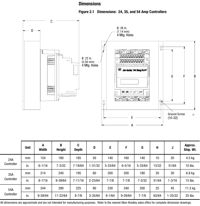
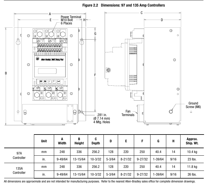
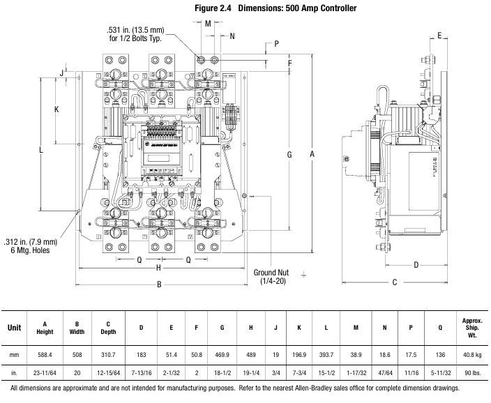
The controller is of an open design and needs to be installed inside a metal casing. The temperature inside the casing should be maintained between 0 ° C and 50 ° C. The heat dissipation power of controllers with different current levels varies (such as 110W for 24A and 2760W for 1000A), and sufficient ventilation openings should be reserved in the ventilation casing (such as 65cm ² openings for 24-54A). Some models (97A and above) come with their own cooling fans, and the fan power supply needs to be wired separately.
Installation specifications
The radiator fins need to be installed vertically, with at least 15cm of space reserved above and below to ensure air circulation; Grounding should be connected to the controller's dedicated grounding screw/terminal post, in accordance with the IEC 5019 grounding identification standard.
(3) Wiring: Power and Control Circuit Configuration
Power wiring
The input (L1/L2/L3) is connected to the power grid, and the output (T1/T2/T3) is connected to the motor. Different current levels of terminals are compatible with different wire specifications (such as 24-54A supporting 2.5-25mm ² wires, 1000A supporting 50-240mm ² wires), and the terminals need to be tightened according to the torque specified in the manual (such as 0.8N · m for 2.5-6mm ² wires).
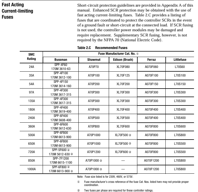
Suggest installing a fast current limiting fuse (such as 24A with 170M 3610-63) to protect the SCR from overcurrent damage; The power factor correction capacitor needs to be installed on the input side of the controller to avoid damage to the SCR caused by capacitor discharge.
Control wiring
The control power supply supports 100-240V AC (± 15%/± 10%) or 24V AC/DC (± 15%/± 10%), and requires separate connection to terminals 11/12. The control module has a power consumption of 40VA, and the cooling fan requires additional power supply (such as 45VA for 97A fans).
Control terminal functions: terminals 13 (enable), 16 (start), 17 (stop), 19-20 (auxiliary contacts 1&2, Form C, can be set to "normal/rated speed"), 29-30 (auxiliary contact 3, can be set to "normal/fault"), some terminals (such as 25-28) are used to connect converter modules or communication modules.
Typical wiring scheme: Provides 12 scenario wiring diagrams, including standard control, dual ramp start, bypass operation, reverse control, manual automatic (SCANPort) control, etc. If the bypass configuration requires the use of an 825 converter module to maintain current monitoring and avoid loss of protection function after controller bypass.
(4) Programming: Parameter Setting and Operation
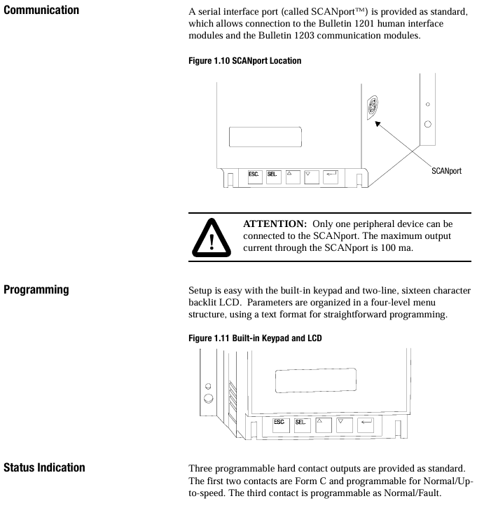
Programming interface: Operated through the built-in 2-line 16 character backlit LCD and 4 keys (ESC/SEL/up and down arrows), the menu is divided into 4 levels (operation layer → mode layer → group layer → parameter layer), supports password protection (prevents unauthorized modification) and "search" mode (only displays non default parameters).
Core parameter group
Basic Setup: Configure startup mode, ramp time, current limit, energy-saving mode, auxiliary contact function, etc., suitable for fast startup.
Advanced Setup: includes dual ramp parameters, overvoltage/undervoltage thresholds, voltage imbalance protection, phase balance, hourly startup times, etc., suitable for complex scenarios.
Calibrate: Input the motor nameplate data (rated current, service factor, motor code, etc.), and use a true RMS clamp meter (accuracy ± 1%) to calibrate the current measurement and ensure the accuracy of the protection function.
Parameter storage: Parameters are stored in RAM by default (lost during power failure) and need to be manually saved to EEPROM (non-volatile). It supports restoring factory default values.
(5) Diagnosis and Troubleshooting: Problem Localization and Resolution
Fault display: The first row of the LCD displays the fault type (such as "OVERLOAD"), the second row displays the fault code (such as "F7"), and the fault buffer stores the last 5 fault records.
Common faults and solutions
Overload (F7): Check if the motor load is too large, if the overload level matches the motor, and if the FLC parameters are entered correctly.
Phase loss (F1-F3): Check if the power grid incoming line and motor wiring are loose, and if the fuse is blown.
SCR open circuit (F23-F25): Measure the resistance between the incoming and outgoing lines of the power module (normally>10k Ω). If there is a short circuit, replace the power module.
Communication Failure (F21): Check if the human-machine interface or communication module connected to SCANPort is disconnected, and if the Logic Mask parameter is set to 4 (enabling communication control).
Maintenance operation: When disassembling the control module, power off first, mark the wires, and then loosen the fixing screws to avoid bending the interface pins; The resistance inspection of the power module requires the use of an ohmmeter to measure the feedback resistance, gate resistance, and thermistor. If they do not meet the standards, the module needs to be replaced.
(6) Serial Communication: Remote Control and Data Interaction
Communication interface: SCANPort is standard and can be connected to 1201 human-machine interface module (programming, start stop control) or 1203 communication module (supporting protocols such as Remote I/O, DeviceNet, DH-485, etc.).
Control Enable: Parameter 85 (Logic Mask) needs to be set to 4 to enable remote control; PLC can send start stop, fault reset, option commands (such as pump stop), receive controller status (running, fault, rated speed) and metering data (current, power).
Communication example: Provide ladder diagram program examples for controllers such as SLC 500 and PLC 5, such as implementing block transfer (BTW/BTR) through Remote I/O, reading motor current, power and other parameters, or performing explicit message transmission through DeviceNet (such as reading fault codes).
Appendix and Supplementary Resources
Appendix A (Specifications): Detailed list of electrical parameters (such as insulation voltage, impulse voltage, dielectric loss tolerance), environmental parameters (altitude 2000 meters, humidity 5% -95%), and measurement accuracy (voltage ± 2%, current ± 5%).
Appendix B (Parameter Table): Summarize the numbers, units, ranges, and default values of all 88 parameters. For example, parameter 30 (Ramp Time # 1) defaults to 10 seconds and ranges from 0 to 30 seconds.
Appendix C (Replacement of Parts): Provide control module, power module SCR、 Models of spare parts such as cooling fans (such as the 24-54A standard control module 40888-490-01-S1FX).
Appendix D (Accessories): Includes accessory models and uses such as protection modules (e.g. 150-N84 for 24-54A 480V systems), terminal lugs, communication cables, converter modules (825-MCM20 compatible with 1-12.5A motors), etc.
Key precautions
Safety regulations: Installation and maintenance require power-off operation to avoid contact with live parts; Emergency stop needs to be configured separately, and functions such as soft stop and SMB braking cannot replace emergency stop, in compliance with NFPA 70E and other standards.
Selection and adaptation: Select the controller model and functional options based on the rated current of the motor, load type (such as pump control options), and starting mode requirements to avoid overload or insufficient functionality.
Calibration requirements: Motor data (FLC, service factor) must be accurately inputted, and current calibration must be performed when the motor is loaded at 70% or more to ensure protection function and measurement accuracy.
- OMRON
- ABB
- General Electric
- EMERSON
- Honeywell
- HIMA
- ALSTOM
- Rolls-Royce
- MOTOROLA
- Rockwell
- Siemens
- Woodward
- YOKOGAWA
- FOXBORO
- KOLLMORGEN
- MOOG
- KB
- YAMAHA
- BENDER
- TEKTRONIX
- Westinghouse
- AMAT
- AB
- XYCOM
- Yaskawa
- B&R
- Schneider
- KONGSBERG
- NI
- WATLOW
- ProSoft
- SEW
- ADVANCED
- Reliance
- TRICONEX
- METSO
- MAN
- Advantest
- STUDER
- DANAHER MOTION
- Bently
- Galil
- EATON
- MOLEX
- DEIF
- B&W
- ZYGO
- Aerotech
- DANFOSS
- Beijer
- Moxa
- Rexroth
- Johnson
- WAGO
- TOSHIBA
- BMCM
- SMC
- HITACHI
- HIRSCHMANN
- Application field
- XP POWER
- CTI
- TRICON
- STOBER
- Thinklogical
- Horner Automation
- Meggitt
- Fanuc
- Baldor
- SHINKAWA
- Other Brands
- UniOP
- KUKA
- Iba
- Beckhoff
-
 Basler D90 96801 100 PCB Card
 -
 Basler XR2002F Voltage Regulator (110 VAC, 48-480 Hz)
 -
 Basler SR8A-2B14B3A Regulator
 -
 Basler 9561500100 Module
 -
 Basler DECS-400 BE1-11 System
 -
 Basler DECS-100-B15 Excitation Control
 -
 Basler SCP 210 Frequency Controller
 -
 Basler SR4A-2B15B3A Static Voltage Regulator
 -
 Basler BE1-32R Power Relay
 -
 Basler PIA2400-17GM Power Interface Adapter
 -
 Basler MVC 232 Manual Voltage Control Module
 -
 Basler SSR 32-12 Static Voltage Regulator
 -
 Basler 5MW AVR Generator Voltage Regulator
 -
 Basler VR63-4B Voltage Regulator
 -
 Basler DECS-100-A05 AVR for Engine Generator
 -
 Basler DECS-100-B15 Automatic Voltage Regulator
 -
 Basler BE1-32R Directional Power Relay
 -
 Basler BE1-87B Differential Relay
 -
 Basler UFOV 260A Protective Module
 -
 Basler 9-2614-02-100 PCB Rev M
 -
Basler DECS-100-B15 Digital AVR
-
 Basler 9284900103 PS DECS-400N
 -
 Basler D4N3H1U Intertie Protection
 -
 Basler DECS-100-B15 A15 AVR
 -
 Basler KR4F Voltage Regulator
 -
 Basler BE26434 T14 Transformer
 -
 Basler SR8A-2B15B3A Regulator
 -
 Westinghouse 774B472A12 AR Relay
 -
Basler DECS-100-B15 AVR
-
Basler XR2002F Regulator 110V
-
Basler SR125-E Static Regulator
-
 Basler SSR 125-12 Regulator
 -
 Basler MOC2599 Motor Pot
 -
 Basler BE1-DFPR Feeder Relay
 -
 Basler CBS 305 Current Boost
 -
 Basler BE1-25 AutoSync
 -
 Basler MVC 300 Voltage Control
 -
 Basler BE3-25A AutoSync
 -
 Basler KR7FF Static Regulator
 -
 Basler 90-49000-100 Regulator
 -
 Basler 880 kVA Dry Type Transformer Specs
 -
 Basler Electric BE1-25 Sync-Check Relay Specs
 -
 Basler SSR 125-12 Voltage Regulator Specs
 -
 Basler Electric BE1-851 Overcurrent Relay Review
 -
Basler Electric 149D930G02 Control Sub-Assembly
-
 Basler Electric BE1-81O/UT Frequency Relay Specs
 -
 Basler Electric BE1-51/27C Overcurrent Relay
 -
 Basler Electric 149D956G02 Industrial Component
 -
Basler Electric BE1-51A Overcurrent Relay Specs
-
 Basler Electric BE1-40Q Loss of Excitation Relay
 -
 Basler DECS-200 Excitation Control System
 -
 Basler DECS-200 Voltage Regulator 56-277V AC / 125V DC
 -
Basler BE1-87T Transformer Differential Relay
-
 Basler RDP-110-S1 Protection Relay
 -
 Basler BE1-700V Digital Protective Relay
 -
 Basler BE1-951 Overcurrent Protection System
 -
 Basler DECS-300 Digital Excitation Control
 -
 Basler DECS-200 Digital Excitation Control
 -
 Basler DECS-200-1C Excitation Control System
 -
Basler DECS-200-1L Digital Excitation Control
-
 Basler Electric BE1-GPS Generator Protection System
 -
Basler Electric DECS-200-1C Digital Excitation Controller
-
 Basler Electric DECS125-15 Excitation Control with Power Module
 -
 Basler Electric BE1-87G Differential Relay
 -
 Basler Electric BE1-11 Protection System I5A3M2P2N0EA00
 -
Basler Electric DECS-200-1C Excitation Control System
-
Basler Electric BE1-11g Generator Protection Relay
-
Basler Electric DECS 125-15-B2C1 V2.0.9 Excitation Control
-
 Basler Electric BE1-81O/UT3ED1JA7N2F Frequency Relay
 -
Basler Electric BE1-81O/UT3EE1YB7N1F Frequency Relay
-
 Basler Electric DECS-200-1L Digital Excitation Control System
 -
Basler DECS125-15-B2C1 Excitation Control
-
 Basler 9507900205 SSR Retrofit Voltage Regulator
 -
 Basler BE2000E Digital Voltage Regulator
 -
 Basler BE1-GPS Generator Protection System
 -
Basler DECS-250-CN1CN1N Digital Excitation Control
-
 Basler DGC-2020 Genset Controller
 -
 Basler BE1-81O UT3ED1LA7N0F Frequency Relay (Variant)
 -
 Basler BE1-81O UT3EE1YA9S0F Frequency Relay (Variant)
 -
Basler BE1-81O Over/Under Frequency Relay
-
Basler DECS125-15 Digital Excitation Control
-
Basler Electric BE1-951 Overcurrent Protection System
-
 Basler Electric BE1-700V Digital Protective Relay
 -
 Basler Electric APR63-5 Automatic Voltage Regulator
 -
Basler Electric BE1-851 Overcurrent Protection System
-
Basler Electric DECS-250-LN1SN1N Excitation Control
-
 Basler Electric BE1-87T Transformer Differential Relay
 -
Basler Electric DECS-200-1L Excitation Control System
-
 Basler Electric 9310300100 DECS-300 Excitation Control
 -
 Basler Electric SSE-N 125-4.5KW Shunt Exciter Regulator
 -
 Basler Electric DGC-2020HD-5NS1DNSBA Genset Controller
 -
Basler Electric BE1-81-O/UT3EE1JB7N1F Frequency Relay
-
Basler Electric BE1-81T1EE1WA0N1F Frequency Relay
-
 Basler Electric BE1-25M1EA6PN5R1F Sync-Check Relay
 -
 Basler Electric BE1-GPS Generator Protection System
 -
Basler Electric DECS-250-LN1SN1N Excitation Control Rev V
-
 Basler Electric DECS-250-CN2CN1N Excitation Control
 -
Basler Electric BE1-50/51B-207 Overcurrent Relay
-
Basler Electric DECS-300-C0N0 Excitation Control System
-
Basler Electric DECS-200 Digital Excitation Control System
-
Basler Electric DECS-250-LN1CN1N Excitation Unit
-
Basler Electric DECS-250 LN2SA1D Excitation Unit Specs
-
Basler Electric BE1-87T Transformer Relay Review
-
Basler Electric BE1-11 Protection System
-
Basler Electric BE1-GPS100-E4N1H1N Protection System
-
 Allen-Bradley 442G-MABH-R Safety Module
 -
 Beckhoff CX1030-0111 PLC Assembly Profile
 -
 FANUC IC693CPU364 PLC Module
 -
 Orange Denmark Type 200816 220 PLC Specs
 -
 OMRON C200H-SNT31 Sysmac PLC Module
 -
 Allen Bradley 20AB022A3AYNANC0 PowerFlex 70
 -
 OMRON C200HW-PCU01 Position Control Unit
 -
 ABB AO845A-eA Analog Output Module
 -
 OMRON CJ1M-CPU22 CPU Unit
 -
 Allen Bradley 100-E265ED11 Contactor
 -
 Honeywell 51304511-100 Interface Module
 -
 SOLEXY BXF3S0101N0018 Gateway Module
 -
 OMRON CJ2H-CPU65 CPU Unit
 -
 Automation Direct GS2-45P0 AC Drive
 -
 M68-2000 2-Axis Motion CNC Controller
 -
 OMRON CJ1M-CPU11 V3.0 PLC CPU Unit
 -
 OMRON CJ1W-NC413 4-Axis Positioning Controller
 -
 OMRON 3G2A3-PRO16 Programming Console HMI
 -
 Siemens 3VT8440-2AA04-2GA2 Molded Case Circuit Breaker
 -
 Siemens 3RT5045 Contactor Series
 -
 OMRON C200HS-CPU01-E SYSMAC PLC Controller
 -
 OMRON C500-NC103-E Positioning Control Unit
 -
 OMRON CJ1W-TC001 Temperature Control Unit


