Allen Bradley 1734 series POINT I/O common terminal module and voltage terminal module
Common Terminal Module (1734-CTM/CTMK): Used to expand the common terminal wiring capability of POINT I/O modules, supporting centralized management of common lines for 8-channel high-density I/O modules. The suffix "K" is the conformal coating version (moisture-proof/corrosive environment), with specifications consistent with the uncoated version.
Allen Bradley 1734 series POINT I/O common terminal module and voltage terminal module
Core framework and scope of application
The document follows the logical mainline of "safety regulations → installation process → wiring guidance → technical parameters", covering the entire process of module preparation to deployment. The applicable products are two types of terminal modules in the 1734 series:
Common Terminal Module (1734-CTM/CTMK): Used to expand the common terminal wiring capability of POINT I/O modules, supporting centralized management of common lines for 8-channel high-density I/O modules. The suffix "K" is the conformal coating version (moisture-proof/corrosive environment), with specifications consistent with the uncoated version.
Voltage Terminal Module (1734-VTM/VTMK): Provides voltage output terminals to distribute power to field devices such as sensors and actuators, and also supports 8-channel configuration. The "K" version is a conformal coating version.
Applicable scenarios: In industrial automation control systems, it is used in conjunction with 1734 series POINT I/O modules (such as digital input/output modules, analog modules) to solve terminal expansion and power distribution problems in high-density wiring scenarios. It is compatible with 1734-TB/TBS (two-piece terminal base) and 1734-TOP/TOPS (one-piece terminal base), but not compatible with 1734-TB3/TB3S and 1734-TOP3/TOP3S bases.

Core content sorting
(1) Preparation in advance: Safety regulations and environmental requirements
Safety prerequisite
Operation qualification: Installation, wiring, and maintenance must be carried out by trained professionals and comply with local electrical regulations (such as NFPA 70E, EN/IEC standards).
Static electricity protection: The module is sensitive to static electricity. When operating, it is necessary to touch a grounded object to discharge and wear a grounding wristband. It is forbidden to touch the pins or components of the circuit board. When idle, it should be stored in anti-static packaging.
Attention to hazardous environments: If used in Class I, Zone 2 hazardous areas, it must be installed in a compliant enclosure and the wiring method must meet local explosion-proof standards; When replacing modules or terminals, power off or ensure that the environment is not hazardous.
Environmental and shell requirements
Environmental level: Suitable for industrial environments with pollution level 2, overvoltage category II (EN/IEC 60664-1), altitude up to 2000 meters (no need to downgrade), prohibited for residential environments.
Shell requirements: The module is of open design and needs to be installed inside a closed shell. The shell should have flame retardant properties (flame propagation level 5VA or non-metallic materials need to be certified), and the interior can only be accessed through tools. The protection level should refer to NEMA 250 or EN/IEC 60529 standards (such as dustproof and waterproof requirements).
Temperature range: Operating temperature -20 ° C~+55 ° C (-4 ° F~+131 ° F), non operating temperature -40 ° C~+85 ° C (-40 ° F~+185 ° F). Exceeding this range can cause module failure.
(2) Installation process: Base, module, and terminal block deployment
1. Install the terminal base (Mounting Base)
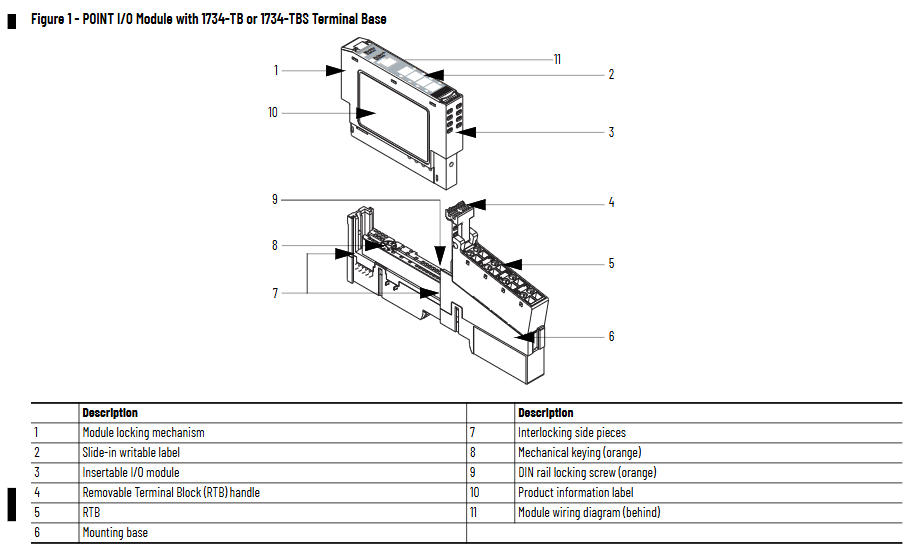
The module needs to be installed on a DIN rail through a 1734-TB/TBS or 1734-TOP/TOPS terminal base (recommended Allen Bradley 199-DR1 rail, compliant with EN 50022 standard). The steps are as follows:
Rail grounding confirmation: Use galvanized chromate passivated steel rails (aluminum/plastic rails are prone to oxidation or poor conductivity, which can cause grounding abnormalities), fix the rails every 200mm (7.8 inches), and install end anchors at both ends. Grounding must comply with the Industrial Automation Wiring and Grounding Guidelines (1770-4.1).
Positioning and installation of the base: Align the base vertically with the installed equipment (adapter, power supply, or existing module), slide down to engage the side interlocking structure with adjacent equipment, and press until the buckle is locked; Confirm that the orange DIN rail locking screw is in a horizontal position (unlocked) to prevent the base from loosening.
End cap protection: The end cap of the terminal base should be covered with an adapter or interface module to prevent electric shock or equipment damage to the exposed interconnected parts.
2. Install terminal module
The module can be deployed before or after installation on the base, and the key steps are as follows:
Base key switch configuration: Use a Phillips screwdriver to rotate the orange key switch on the base clockwise to align the corresponding module type number with the base groove (default position 1, refer to the module label for details), ensuring correct mechanical positioning.
Module installation: Insert the module vertically into the base and press it until the locking buckle is engaged; If the base is powered on, inserting/removing the module may generate an arc. In hazardous environments, power should be cut off first to avoid explosions caused by the arc.
- ABB
- General Electric
- EMERSON
- Honeywell
- HIMA
- ALSTOM
- Rolls-Royce
- MOTOROLA
- Rockwell
- Siemens
- Woodward
- YOKOGAWA
- FOXBORO
- KOLLMORGEN
- MOOG
- KB
- YAMAHA
- BENDER
- TEKTRONIX
- Westinghouse
- AMAT
- AB
- XYCOM
- Yaskawa
- B&R
- Schneider
- Kongsberg
- NI
- WATLOW
- ProSoft
- SEW
- ADVANCED
- Reliance
- TRICONEX
- METSO
- MAN
- Advantest
- STUDER
- KONGSBERG
- DANAHER MOTION
- Bently
- Galil
- EATON
- MOLEX
- DEIF
- B&W
- ZYGO
- Aerotech
- DANFOSS
- Beijer
- Moxa
- Rexroth
- Johnson
- WAGO
- TOSHIBA
- BMCM
- SMC
- HITACHI
- HIRSCHMANN
- Application field
- XP POWER
- CTI
- TRICON
- STOBER
- Thinklogical
- Horner Automation
- Meggitt
- Fanuc
- Baldor
- SHINKAWA
- Other Brands


