
SIEMENS 3AH3 vacuum circuit breaker
SIEMENS 3AH3 vacuum circuit breaker
Product Overview and Core Features
Basic positioning: Siemens 3AH3 vacuum circuit breaker belongs to medium voltage equipment, with document version 2018 (HG 11.03), replacing the old version 2010. The product production and sales follow ISO 9001, ISO 14001, BS OHSAS 18001 certification management system.
Core advantages:
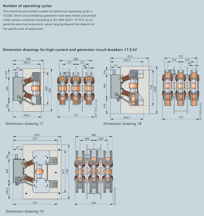
Maintenance free design: Under normal conditions (compliant with IEC 62271-1), there is no need for re lubrication or adjustment throughout the entire service life, and the characteristics are not affected by switching frequency or idle time. It supports up to 10000 operating cycles.
Wide voltage coverage: Suitable for the conventional medium voltage range of 7.2kV-40.5kV, meeting the needs of industrial and generator scenarios.
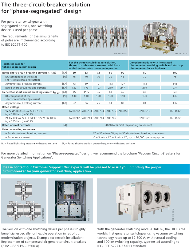
High load capacity: The maximum rated normal current of conventional models is 6300A, and the maximum short-circuit breaking current is 72kA; under the "phase separation" design scheme, the maximum rated normal current is 12000A, and the maximum short-circuit breaking current is 90kA.
Product Classification and Applicable Standards
1. Product classification and scenarios
Product type follows standard core applicable scenarios and key enhanced features
Conventional high-voltage circuit breakers IEC 62271-100 are used in industrial scenarios (such as oil refineries) to control small inductive/capacitive load currents to high-voltage short-circuit currents-
Generator circuit breaker (3AH3 6/7/8 series) IEC 62271-100+IEC/IEEE 62271-37-013 Generator operation, switching between generator power supply failure and system power supply failure 1. Coping with generator power supply failure: high DC component, no current zero point; 2. Coping with system power supply failures: higher TRV rise rate; 3. Higher testing voltage level
Split phase design circuit breaker IEC 62271-100+IEC/IEEE 62271-37-013 for large generator switchgear, single-phase isolating switch (independent enclosure) 1. Optimize parallel operation; 2. The maximum short-circuit breaking current is 90kA; 3. The maximum rated normal current is 12000A
2. General standard compliance
Basic standards: IEC 62271-100 (for circuit breakers), IEC 62271-1 (for medium voltage equipment) VDE 0671
Endurance level: All 3AH3 vacuum circuit breakers meet the E2, M2, C2, and S1 levels (IEC 62271-100)
Structure and Working Principle
1. Core structure (including component functions)
Core functions of structural components
Pole component (1) vacuum arc extinguishing chamber (6), upper/lower arc extinguishing chamber bracket (5/7), post insulator (3) 1. Vacuum arc extinguishing chamber: based on more than 40 years of mature vacuum switch technology, arc extinguishing is achieved; 2. Air insulation design, easy to clean insulation components; 3. Bear the external force and contact pressure of switch operation
Operating mechanism box (2) includes energy storage mechanism, release device, auxiliary switch, indicator, and actuator 1. It accommodates all operating mechanisms; 2. The configuration of secondary devices can be adjusted according to application scenarios to meet diverse needs
Transmission component operating rod (4), lever transmission switch action, connecting operating mechanism and pole assembly
2. Key operational mechanisms
Energy storage mechanism: The closing spring is an energy storage component that can store energy electrically or manually, and is locked after the energy storage is completed; When closing, unlock through the local "ON" button (mechanical) or remote control (electric). During the closing process, charge the opening/contact pressure spring, and automatically re store energy after discharge. It supports the OPEN-CLOSE-OPEN operation sequence.
Free release mechanism: in accordance with IEC 62271-100, if a closing command is issued and an opening command is received, the moving contact returns to the opening position and maintains it, avoiding continuous closing opening "pumping".
Closing method:
Standard configuration: Remote electric closing, local mechanical unlocking closing spring (manual mechanical closing)
Optional configuration: Manual electric closing (electrically controlled closing circuit through button, compatible with switch equipment interlocking)
3. Types and functions of release devices
Release type, power supply method, core function
Closing the soleoid DC/AC unlocks the stored energy closing spring to achieve electrical closing
External power supply (DC/AC) for shunt release, connected to voltage transformer in special circumstances. 1. Automatic disconnection through protective relay; 2. Electrical manual disconnection
When the CT operated release has no external auxiliary power supply (such as no battery), it is triggered by a protective relay (such as overcurrent time protection). When the tripping current exceeds 90% of the rated normal current, the energy storage mechanism is unlocked and the circuit is opened
When the undervoltage release circuit breaker is closed, it is permanently connected to the secondary/auxiliary voltage. When the voltage is lower than the preset value, it is unlocked and opened through the energy storage mechanism; 2. Can be connected to a voltage transformer, which automatically opens when the voltage is too low; 3. Can be paired with energy storage components to achieve delayed disconnection
Environmental conditions and technical parameters
1. Environmental conditions (compliant with IEC 60721-3-3)
Key limitations of environmental category level
The lower limit of low temperature in the 3K4 climate environment is -5 ℃, with no icing or wind blown precipitation
Biological Environment 3B1-
Mechanical environment 3M2-
Chemical active substance 3C2-
Mechanical active substance 3S2 requires cleaning of insulation components
2. Current carrying capacity and insulation strength
Current carrying capacity: The rated normal current is based on an ambient air temperature of 40 ℃ (open type switchgear), and can be increased when the temperature is below 40 ℃. The rated current levels include 1250A, 2000A, 2500A, 3150A, 4000A, 5000A, and 6300A (corresponding to characteristic curves 1-7).
Insulation strength:
Reference conditions: At an altitude of 1000m (above sea level), the rated lightning impulse withstand voltage and rated short-time power frequency withstand voltage are taken according to the "Technical Data" section.
High altitude correction: When the altitude is greater than 1000m, it needs to be adjusted according to the formula U ≥ U 0 × K a (U is the reference environmental withstand voltage, U 0 is the required withstand voltage of the installation site, K a is the altitude correction factor, which increases with altitude).
Example: When a lightning impulse withstand voltage of 75kV is required at an altitude of 2500m, the reference environment must be at least 90kV (90kV ≥ 75kV × 1.2).
3. Capacitor switch capability (endurance class C2, IEC 62271-100) Rated voltage U r (kV) Rated line charging breaking current I I (A, r.m.s.) Rated cable charging breaking current I c (A, r.m.s.) Rated single capacitor group breaking current I sb (A, r.m.s.) Rated back-to-back capacitor group breaking current I bb (A, r.m.s.) Inrush current frequency f bl (Hz)
7.2 10 10 400 400 4250
12 10 25 400 400 4250
17.5 10 31.5 400 400 4250
24 10 31.5 400 400 4250
36 10 50 400 400 4250
40.5 10 50 400 400 4250
Note: The capacity of the circuit breaker capacitor switch is 0.7 × I r of the standard specification
Selection and Configuration Guide
1. Order number structure (16 digits)
Explanation of Position Meaning
1-3 superior group/main group/sub group 1: switchgear; 2: Circuit breaker; 3 digits: Circuit breaker series
The 4-8 bit main device includes design and main device parameters (voltage, current, pole spacing, etc.)
9-16 position secondary equipment operating mechanism, release, operating voltage, auxiliary equipment, etc
Order code supplementary configuration 9/Equipment version marked with "Z" digit, supplemented with 3-digit code (a n a format), can be continuously added multiple times
Add "- Z" to the order number for special version customization requirements, followed by descriptive code; Y99 is used for unspecified special requirements and needs to be negotiated with Siemens
2. Selection of main equipment (by voltage level)
Taking some key voltage levels as examples, demonstrate the adaptation relationship between rated short-circuit breaking current and rated normal current (excerpt):
Rated voltage (kV) Rated short-circuit breaking current (kA) Rated normal current (A) - Pole distance (mm) Adaptation
7.2 50 1250(210)、2500(210/275)、4000(275/350)
7.2 63 2000(275)、3150(275)、4000(275/350)
12 50 1250(210)、2500(210/275)、4000(275/350)
12 63 2000(275)、3150(275)、4000(275/350)
36 31.5 1250(350)、2500(350)、4000(350)
36 40 3150(350)、4000(350)
Note: "n" indicates that the combination is optional
3. Selection of secondary equipment (core configuration)
Description of optional scope of configuration items
Operating mechanism electric (excluding hand crank), manual (including hand crank) Hand crank can be ordered separately as accessories
Closing method: Solenoid+manual mechanical closing, manual electric closing. Manual electric closing can be adapted to switch equipment interlocking to prevent accidental closing
Up to 3 release combinations can be used (based on 1 shunt release, additional shunt/CT operation/undervoltage release can be added). Please refer to page 19 of the document for specific combinations
Auxiliary switches 6NO+6NC, 12NO+12NC-
Plug/Terminal: 24 pole terminal block, 24 pole plug, 64 pole plug. The interface of the 64 pole plug can be connected to idle auxiliary contacts by the user
Interlock free, mechanical interlock, mechanical interlock adapted to circuit breaker handcart, withdrawal component or isolation switch
4. Additional equipment (some key options)
Additional equipment function order code
Anti condensation heating 230V AC, 50W, anti condensation Z A30
Silicon free design suitable for special environmental requirements Z A31
Low temperature adaptation (-25 ℃) can operate Z A40 in an environment of -25 ℃
3AH37 horizontal installation (≥ 5000A) 3AH37 model 5000A and above horizontal installation supplement Z A70
Gold plated auxiliary switch enhances contact reliability and adapts to different interfaces Z A17/Z A18/Z A20/Z A21
Routine test certificate with seal and report/report only/with seal signature Z F19/Z F20/Z F21
Accessories and after-sales support
1. Main accessories and spare parts (excerpt)
Attachment/Spare Part Name Specification/Remarks Order Number
Hand crank short/standard/long 3AX15 30-4A/4B/4C
Lubricant 180g Kl ü ber Isoflex Topas L32N 3AX11 33-3H
Cable bundle for 64 pole plug/24 pole plug/24 pole terminal block 3AX11 34-2D/2B/2C
Vacuum arc extinguishing chamber compatible with 3AH3117-7 model 3AY17 15-2J
Vacuum arc extinguishing chamber compatible with 3AH3228-8 model 3AY17 15-4J
Closing soleoid 24V DC 3AY15 10-5K
Undervoltage release 24V DC 3AX11 03-2B
2. Key requirements for after-sales service
Ordering spare parts: Equipment model, serial number, and manufacturing year (all on the nameplate) must be provided to ensure compatibility.
Modification requirements: When modifying the release/solenoid, the installation component order number must also be specified; Other additional equipment includes necessary installation components.
Professional operation: The vacuum arc extinguishing chamber and some spare parts need to be replaced by trained personnel..
- OMRON
- ABB
- General Electric
- EMERSON
- Honeywell
- HIMA
- ALSTOM
- Rolls-Royce
- MOTOROLA
- Rockwell
- Siemens
- Woodward
- YOKOGAWA
- FOXBORO
- KOLLMORGEN
- MOOG
- KB
- YAMAHA
- BENDER
- TEKTRONIX
- Westinghouse
- AMAT
- AB
- XYCOM
- Yaskawa
- B&R
- Schneider
- KONGSBERG
- NI
- WATLOW
- ProSoft
- SEW
- ADVANCED
- Reliance
- TRICONEX
- METSO
- MAN
- Advantest
- STUDER
- DANAHER MOTION
- Bently
- Galil
- EATON
- MOLEX
- DEIF
- B&W
- ZYGO
- Aerotech
- DANFOSS
- Beijer
- Moxa
- Rexroth
- Johnson
- WAGO
- TOSHIBA
- BMCM
- SMC
- HITACHI
- HIRSCHMANN
- Application field
- XP POWER
- CTI
- TRICON
- STOBER
- Thinklogical
- Horner Automation
- Meggitt
- Fanuc
- Baldor
- SHINKAWA
- Other Brands
- UniOP
- KUKA
- Iba
- Beckhoff
- ADLINK
-
 Rolls Royce H1111.0204 Ship Main Controller
 -
 Basler Electric BE3-32-3AC Reverse Power Relay 9 1376 00 105
 -
 Basler Electric BE3-25-1A1N4 Synch Check Relay 9319100100
 -
 Basler Electric SR4A-2B15B3A Static Voltage Regulator
 -
 Basler Electric SR4A-2B15B3E Static Voltage Regulator
 -
 Basler Electric 9170818100 Solid State Protective Relay
 -
 Basler Electric AEC63-7 Analog Excitation Controller
 -
 Basler Electric 17483 Auxiliary Module
 -
 Basler Electric BE1-59 Over Voltage Relay
 -
 Basler Electric 21600-101 Control Module
 -
 Basler Electric KR2F Generator Voltage Regulator 9056600100
 -
 Basler BE1-CDS Current Differential System
 -
 Basler Electric CBS 212 Current Boost System 9 2650 00 100
 -
 Basler Electric IFM-150 Firing Circuit Chassis
 -
 Basler Electric BE1-60 Voltage Balance Relay C1F A1P D0C3F
 -
 Basler Electric BE1-32R Power Relay A2E D1R A0N0F
 -
Basler Electric BE1-32R Power Relay A2E D1R A0N0F
-
 Basler Electric 8650C80G01 Isolation Transducer PCB Board
 -
 ETEL EA-P2M-300-4/7.5A-0100-01 AccurET Modular 300 Servo Drive
 -
 Basler Electric 87T Transformer Differential Relay
 -
 Basler Electric BE-6868 Power Transformer 5950007559202
 -
 Basler Electric PRS250 Veri-Sync Relay 9088800102
 -
 Basler Electric SCP-250-G-60 VAR Power Factor Controller
 -
 Basler DECS-150 AVR 1NS2V1N1S Voltage Regulator
 -
 Basler UFOV 260A Under Frequency Overvoltage Module
 -
 Basler MOC2 199 Motor Operated Control – Overview and Setup
 -
 Basler BE3-49R-5K5A1 Temperature Relay – Complete Guide
 -
Basler BE 20035 001 Transformer – Technical Data and Installation
-
 Basler BE 02727 001 Transformer – Specifications and Usage
 -
 Basler BE127 Under Voltage Relay – Features and Application Guide
 -
Basler CBS377 Current Boost System – Complete Technical Guide
-
 Basler BE1-87G P/N 9170818100 Differential Relay – In-Depth Specs
 -
Basler BE1-87G Generator Differential Relay – Technical Overview
-
Basler Electric SR4A2B16 SVR Static Voltage Regulator – Complete Guide
-
 Basler Electric 9261500101 Power Supply Module
 -
 Basler Electric AEM-2020 Analog Expansion Module
 -
Basler Electric DGC-2020 Digital Genset Controller 51BRBNEAH001
-
Basler Electric BE1-59N Ground Fault Overvoltage Relay
-
 Basler Electric BE1-59N-A5E-E1L-N0S1F Neutral Overvoltage Relay
 -
Basler Electric MOC2499 Motor Operator Control Potentiometer 9072300430
-
 Basler Electric BE1-50/51M Overcurrent Relay
 -
 Basler Electric 9148100106 MOC3502 Solid State Relay 250VDC 0.25A
 -
 Basler Electric CBS 212 Current Boost System 9265000100
 -
 Basler Electric 10493002 Control Module
 -
Basler BE1-32R D3E E1R A0N1F Power Relay
-
 Basler SR8A2B15B3A Static Voltage Regulator
 -
 Basler IFM-105 Firing Circuit Chassis 9324100105
 -
Basler SR4A2B05B3A Static Voltage Regulator
-
 Basler BE151G1EB6PB0N0F Protective Relay
 -
Basler BE1-59 Electric Over Voltage Relay
-
 Basler 277 Static Programmable Powerline Carrier Channel
 -
 Basler BE1-32R D1E A1P A0N1F Power Relay
 -
Basler SR4A1B07B3A Static Voltage Regulator
-
 Basler Electric BE1-700 Digital Protective Relay
 -
Basler Electric SR8A-2B01B3A Static Voltage Regulator
-
 Basler Electric SR4A-2B01B3E Static Voltage Regulator
 -
 Basler Electric 9017709102 PC Board
 -
Basler Electric SR4A-2B01B3A Static Voltage Regulator
-
 Basler Electric PRS-250 Veri-Sync Relay
 -
 Basler Electric 9066800102 Excitation Support System
 -
Basler Electric BE1-87G Generator Differential Relay 9 1708 18 100
-
 Basler Electric 36T865-2 BE03752001 Power Supply
 -
 Basler Electric M-300 149D940G02 Power Supply
 -
 Basler Electric ACA2040-25GM 4Mp 25Fps Area Scan Camera
 -
 Basler BE1-87G-S1A-A1C-A0N0 Differential Relay
 -
Basler SR8A-2B06B3E Static Regulator SR8A2B06B3E
-
 Basler SCP-210 Frequency Controller 9095400100
 -
 Basler BE1-59-A3E-A1J-N1N3F Overvoltage Relay BE159A3EA1JN1N3F
 -
Basler 9 2011 11 100 Bracket Mounted Terminal Unit
-
Basler 9 1606 00 101 Voltage Regulator
-
 Basler CBS-377 Current Boost System 9109600102
 -
 Basler 8650C72 Exciter Control Module PCB Rev 5
 -
 Basler C2EE1PA0N1F BE1-32R Reverse Power Relay
 -
 ADLINK HPCI-14S12U - Industrial Control Backplane 12PCI Backplane PCI-14S Passive Backplane
 -
-0010.png) ADLINK PCIe-GIE74C - image acquisition card 4-CH GigE Vision PoE+ Frame Grabber
ADLINK PCIe-GIE74C - image acquisition card 4-CH GigE Vision PoE+ Frame Grabber -
-0010_1.png) ADLINK PCI-8164 - control card 4-Axis Advanced Motion Controller Board
ADLINK PCI-8164 - control card 4-Axis Advanced Motion Controller Board -
 ADLINK PCIe-U304 - 4 Port USB3 PCIe Frame Grabbers USB Screw Hole Card
 -
 ADLINK PCI-9112 - Multi-Function Data Acquisition Card DAQ Card
 -
 ADLINK PCI-7432 - 51-12013-0A50 4-CH Isolated Numérique I/O PCI Cartes Digital I/O Card
 -
 ADLINK PCA-6106P3-0C1 REV.C1 - backplane 6-Slot Passive Backplane Board
 -
 ADLINK PCI-7224 - 24-CH Opto-Isolated Digital I/O PCI Board
 -
 ADLINK CPCI-7433R(G) - Digital Input Board Rear I/O CompactPCI Card
 -
 ADLINK EBP-13E4 - 51-46703-0A30 Industrial PC Backplane Passive Backplane
 -
 ADLINK PCIE-HDV62 - Image acquisition card High Definition Video Frame Grabber
 -
 ADLINK EBP-13E4 - 51-46703-0A30 Industrial Backplane Board Passive Backplane
 -
 ADLINK 90111-B1 / CPCI-6770 - PCB CPU MODULE CompactPCI Single Board Computer
 -
 ADLINK PCI-7248 - DATA ACQUISITION PCI CARD 48-CH Parallel Digital I/O Board
 -
 ADLINK PCI-7230 - 51-12003-0a50 board PCI7230 32-CH Isolated Digital I/O Card
 -
 ADLINK PCI2A000CB - 51-20000-0B30 Multi-Function DAQ Card Baseboard
 -
 ADLINK PCI-8134-005 - 4-Axis Motion Controller Card
 -
 ADLINK PCI-7224 - 24-CH Opto-Isolated Digital I/O PCI Card
 -
 ADLINK PCI-7434 - 64-CH Isolated Digital Output Card
 -
 ADLINK PCI-8132 - motion control card 2-Axis Servo & Stepper Controller
 -
 ADLINK PCI-8134 - Motion Controller PCI Card 4-Axis Controller Board
 -
 ADLINK PCI-8164 - Motion Control Card 51-12406-0A40 4-Axis Controller
 -
 ADLINK 51-12001-0C20 - Circuit Board Data Acquisition Interface Module Hardware
 -
 ADLINK NuPR0-840 - industrial control motherboard Full-Size PICMG CPU Board
 -
 ADLINK PCI-7444 - 51-12023-0A10 card 128-CH Isolated Digital Output Board
 -
 ADLINK PCI-1612B - data acquisition card 4-Port RS-232/422/485 Serial Communication Card
 -
 ADLINK PCI-6208V 009 - 8/16-CH 16-Bit Analog Output Cards PCB-I-E-482=6BX3
 -
 ADLINK NUPRO-935A/LV - industrial control motherboard Full-Size PICMG SBC Board
 -
 ADLINK PCI-9114DG - Multi-Function DAQ Card Data Acquisition PCI Card
 -
 ADLINK ACL-7130 - Data acquisition card Isolated Digital I/O Board
 -
 ADLINK ABX-6300D-4E1-BP - board ABX6300D4E1BP Video Interface Expansion Card
 -
 ADLINK CPCI-6940 - CPCI-6940/D1539/M16-0(EA)-000E 6U CompactPCI Processor Board
 -
 ADLINK NuPRO-760 - industrial control motherboard Half-Size PICMG SBC CPU Board
 -
 ADLINK IMB-M42H (G)-0020 - industrial control motherboard LGA1155 Micro-ATX Mainboard
 -
 ADLINK RTV-24 / PCI-MP4S - 51-12519-1C30 4-Channel Real Time Video Capture Board
 -
 ADLINK PCI-8134 - 4-Axis Servo & Stepper Motion Controller Card
 -
 ADLINK MXC-6101D - V.PC000.002.ST.00 Box PC Configurable Embedded Computer
 -
.png) ADLINK PCI-8134A - 51-12421-0A10 Motion Control Card 4-Axis Controller Card
ADLINK PCI-8134A - 51-12421-0A10 Motion Control Card 4-Axis Controller Card -
 ADLINK DIN-100S / DIN-100SA1 - Technology SCSI-II TB 100-PIN Terminal Block Board
 -
.png) ADLINK DIN-812M001 / DIN812M001 - 51-14034-0A1 51140340A1 Terminal Module Breakout Interface
ADLINK DIN-812M001 / DIN812M001 - 51-14034-0A1 51140340A1 Terminal Module Breakout Interface -
_1.png) ADLINK PCI-8164 - Servo motion control 4-Axis Advanced Controller Card
ADLINK PCI-8164 - Servo motion control 4-Axis Advanced Controller Card -
 ADLINK PCIe-GIE64 - Acquisition card GigE Vision PoE+ Frame Grabber
 -
 ADLINK M-302 - Industrial control motherboard ATX PC Board Mainboard
 -
 ADLINK PCI-8134 - Motion Controller PCI Card 4-Axis Controller Board
 -
 ADLINK PCI-RTV24 - Image capture card Analog Video Frame Grabber
 -
 ADLINK PCI-8102 - Motion control card 2-Axis Servo & Stepper Controller Board
 -
 ADLINK PCI-9112 REV.B1 - Card Multi-Function Data Acquisition Card
 -
 ADLINK HSI-DI32-M-N / HSL-TB32-M-DIN - Discrete I/O MODULE Distributed Automation Module System
 -
 ADLINK PCI-7296 - IO card REV.A3 96-CH Parallel Digital I/O Card
 -
-0020.png) ADLINK DIN-814P-A4 / 814Y - terminal board Motion Control Interface Block
ADLINK DIN-814P-A4 / 814Y - terminal board Motion Control Interface Block -
 ADLINK DIN-814P-A4 - 51-14056-0A10 PCB-I-E-2736=ZA01 Screw Terminal Board Breakout
 -
 ADLINK M-322 - motherboard Industrial Control Computer Mainboard
 -
 ADLINK NUPRO-406 REV:B1 - industrial control motherboard Full-Size PICMG CPU Board
 -
 ADLINK AMP-204C - card DSP-Based 4-Axis Advanced Pulse-Train Controller
 -
 ADLINK HPCI14S REV.B1 - industrial computer baseboard 14-Slot Passive Backplane


