
TEKTRONIX 5A22N Differential Amplifier
Core features:
Bandwidth: Maximum DC to 1MHz, bandwidth can be limited by HF-3dB (high frequency) and LF-3dB (low frequency) switches to improve signal-to-noise ratio;
Deflection coefficient: The knob skirt edge emits light and displays, supporting automatic scaling of 10X encoding probes;
Other: High common mode rejection ratio (CMRR), variable DC offset, suitable for displaying small signals at large DC levels.
TEKTRONIX 5A22N Differential Amplifier
Operation Instructions (Section 1)
1. Instrument description
Positioning: High gain differential amplifier plug-in unit, used for 5100 series oscilloscopes, can directly couple input to achieve high sensitivity.
Core features:
Bandwidth: Maximum DC to 1MHz, bandwidth can be limited by HF-3dB (high frequency) and LF-3dB (low frequency) switches to improve signal-to-noise ratio;
Deflection coefficient: The knob skirt edge emits light and displays, supporting automatic scaling of 10X encoding probes;
Other: High common mode rejection ratio (CMRR), variable DC offset, suitable for displaying small signals at large DC levels.
2. Panel controls and interfaces (key functions)
Control/Interface Function Description
Display switch plugin working status (only valid for vertical cabin), when turned on, the knob skirt light is on
POSITION adjusts the trajectory position on the screen
HF -3dB/LF -3dB - HF -3dB: 1-3-10 sequence with 7 levels (0.1kHz-1MHz), reducing the upper bandwidth limit and improving signal-to-noise ratio
-LF-3dB: 1-10-100 sequence with 7 levels (DC-10kHz), limited to 2Hz during AC coupling; adjustable DC offset in DC OFFSET level
VOLTS/DIV - Calibration mode: 18 levels 1-2-5 sequence, 10 μ V/Div to 5V/Div (accuracy 2%)
-Variable gear: Non calibrated continuous adjustment, range extended to 12.5V/Div
DC OFFSET (COARSE/FINE) requires LF-3dB to be placed in the DC OFFSET mode to achieve display adjustment of small signals at large DC levels
STEP ATTEN DC BAL balanced input amplifier to reduce trajectory offset during VOLTS/DIV switching
Input coupling button (AC/DC/GND/PRE CHG) - AC: capacitive coupling (blocking DC); DC: direct coupling
-GND: Input ground (disconnect signal); PRE CHG: Press AC+GND to pre charge the coupling capacitor to the signal DC level
+/-Input interface BNC interface,+positive signal deflects upwards, - positive signal deflects downwards; Equipped with a 10X encoded probe ring
3. Basic operation steps
Installation and startup:
Insertion: Align the plug-in guide rail with the 5100 series module compartment (priority vertical compartment: center/left; X-Y operation can be inserted into the horizontal compartment), and the panel should be level with the oscilloscope;
Power on: Adjust the oscilloscope brightness to the lowest level → Power on → Preset time base (2ms/Div) and trigger (automatic trigger).
Initial setup:
Set PLAY to ON,+/- input coupling to DC+GND, POSITION and STEP ATTEN BAL to median, HF/LF-3dB to full bandwidth, VOLTS/DIV to 50mV/Div, and variable gear to CAL (clockwise to bottom).
Preheating and trajectory adjustment:
Preheating: Short term DC measurement for 5 minutes, long-term DC measurement for 15 minutes;
Adjust the brightness to normal, and the trajectory should be near the center of the scale. Use POSITION to move the trajectory to 2 grids below the centerline.
Example of signal measurement:
Single ended DC coupling:+input connected to 400mV peak to peak calibration signal → release+GND → display 4 grid square waves (bottom alignment step 3 reference line);
Single ended AC coupling: POSITION moves the trajectory from bottom to center → presses AC → the trajectory shifts downward by about 2 grids (to the average value);
Differential AC coupling:+/- input connected to dual input cable → - input set to AC → display straight line (common mode signal suppressed).
4. Key precautions
Input protection: The maximum voltage of the input FET gate is ± 12V (diode clamp), and the input fuse will melt when the signal source current exceeds 1/16A;
Pre charge (PRE CHG): When measuring AC signals containing DC components, first connect the AC+GND signal → wait for 1 second for charging → release GND to avoid damaging the signal source due to coupling capacitor charging current;
High impedance input: When VOLTS/DIV is in the 50mV-10 μ V range, removing the circuit board jumper can disconnect the 1M Ω ground resistor, achieving high impedance input (requiring the signal source to provide a DC path for FET gate current).
5. Electrical characteristics (core parameters)
Specific parameters of characteristics
Bandwidth (-3dB) - DC coupling: DC to ≥ 1MHz (independent of deflection coefficient)
-AC coupling: 2Hz to ≥ 1MHz
Common mode rejection ratio (CMRR) - DC coupling: 10 μ V/Div-0.1mV/Div range ≥ 100dB (DC-30kHz, 20Vp-p sine wave); 0.1V/Div-5V/Div mode ≥ 50dB (100Vp-p sine wave)
-AC coupling: ≥ 80dB at 5kHz and above, reduced to 50dB at 10Hz
DC offset range -10 μ V/Div-50mV/Div range: ± 0.5V
-100mV/Div-5V/Div mode: ± 50V
Input RC 1M Ω (± 0.1%) in parallel at approximately 47pF
Maximum input voltage DC coupling: 10V (DC+peak AC) (10 μ V-50mV range); 350V (DC+peak AC) (100mV-5V range)
-AC coupling: 350VDC+10V peak AC (10 μ V-50mV range, pre charged); 350V (DC+peak AC) (100mV-5V range)
Noise at full bandwidth (DC-1MHz) ≤ 20 μ V (25 Ω source resistance, tangent measurement)
Working principle (Section 2)
1. Overall block diagram path
Signal → Input coupling (AC/DC/GND) → Input attenuator (1X/100X, frequency compensation) → Pre amplifier (differential structure, floating ground power supply) → Low frequency limiting circuit (LF-3dB switching) → Gain switching stage (VOLTS/DIV control) → Offset generator (DC OFFSET) → Isolation stage (emitter follower) → Output amplifier (push-pull structure, POSITION adjustment) → Trigger signal amplifier (output to time base plugin, 0.25V/display panel).
2. Analysis of core circuit modules
Input attenuator:
Attenuation ratio: VOLTS/DIV 0.1V-5V range with 100X attenuation, 10 μ V-50mV range with 1X attenuation;
Features: Frequency compensation, maintaining 1M Ω//47pF input characteristics, balancing common mode signals through R132 (Atten DC CMR).
Pre amplifier:
Structure: Two identical operational amplifiers form a differential circuit (Q150A/B, Q190A/B, Q200A/B);
Floating power supply: composed of Q170/Q176 (constant current source) and VR173/175/176 (Zener transistor), it maintains the stability of the amplification device operating point and improves CMRR as the common mode signal changes;
Gate current compensation: Regulate R121/R127 to offset FET gate leakage current (≤ 100pA) and avoid high-sensitivity offset (such as 100pA × 1M Ω=100 μ V offset in 10 μ V/Div mode, which may cause trajectory offset screen).
DC offset generator:
Structure: Q240/Q244/Q246A/B form a voltage comparator, with VR251 (transistor) providing a reference voltage;
Function: By adjusting COARSE (R260) and FINE (R268), offset current is generated to cancel the DC component of the input signal, with a maximum cancellation of 0.5V.
Output amplifier:
Structure: Push pull amplifiers Q348/Q352, R351 (GAIN) adjust the total gain to match the requirements of the host;
Position adjustment: Q360/Q362 (positioning current drive), R360 (POSITION) changes the current to adjust the static position of the CRT beam.
Calibration (Section 3)
1. Calibration prerequisites and preparations
Applicable scenarios: After instrument maintenance, long-term use (component aging) leads to accuracy deviation;
Environmental requirements: Temperature of 20-30 ℃, preheating for 20 minutes;
Equipment disassembly: Remove the left protective cover of 5A22N and the left panel of 5100 series oscilloscope (or use plug-in extender 067-0645-00);
Initial settings: Set the 5A22N control to POSITION median LF-3dB=1Hz、HF-3dB=1MHz、VOLTS/DIV=50mV、 Variable gear=CAL,+/- input=DC+GND, STEP ATTEN BAL median; The 5B10N time base is set to automatic triggering,+slope, and AC coupling.
2. Required testing equipment (including accessories)
Specific requirements/model examples for equipment types
Oscilloscope System 5100 Series (including 5B10N Time Base Plugin)
Constant amplitude sine wave generator frequency 2Hz-1MHz, output 0.5V-40Vp-p (such as General Radio 1310-B)
Standard amplitude calibrator 1kHz square wave, output 5mV-50V, accuracy ± 0.25% (recommended 067-0502-01)
Accessories - Coaxial Line: 50 Ω, 42 inches, BNC(012-0057-01)
-Dual input cable: matching signal path, BNC(067-0525-00)
-1000:1 voltage divider: accuracy ± 0.2% (067-0529-00)
-Input RC Normalizer: 1M Ω× 47pF (067-0541-00)
-Serial terminal: 50 Ω, accuracy ± 2% (011-0049-01)
3. Key Calibration Steps (Core 8 Steps)
Step attenuator balance:
R292 (AC STEP ATTEN BAL): Switch between VOLTS/DIV 50mV-0.1V to minimize trajectory offset;
Adjust R318 (VAR BAL): Shift the variable gear from CLOCKWISE to COUNTERCLOCKWISE to minimize trajectory deviation;
Adjust R250 (COARSE DC BAL): Set LF-3dB to DC, switch VOLTS/DIV 50mV-0.1V, and minimize trajectory offset.
Gate current regulation:
+Input to 50 Ω terminal → LF-3dB=DC → Release+GND → Switch+AC, adjust R121 (+GATE CURRENT), minimize trajectory offset;
-Input to 50 Ω terminal → press+GND → release - GND → switch - AC, adjust R127 (- GATE CURRENT), minimize trajectory deviation.
Attenuator DC common mode rejection:
Release+/- GND → VOLTS/DIV=0.1V →+/- Input through dual cables connected to a 50V square wave (calibrator) → Adjust R132 (ATT DC CMR) to display the minimum amplitude.
Input compensation:
-GND pressed ->VOLTS/DIV=50mV ->+input connected to 0.5V square wave (normalized by RC) ->C118 adjusted (Atten Time Constant), with the best square wave front;
Similarly, input C148, C145, C142.
Amplifier gain calibration:
VOLTS/DIV=10mV →+input connected to 50mV square wave → adjust R351 (GAIN), display amplitude exactly 5 grids;
Turn the variable gear to COUNTERCLOCKWISE, with a display amplitude of<2 grids, and then turn it back to CAL.
VOLTS/DIV accuracy check:
VOLTS/DIV=5V →+input connected to 20V square wave (through 1000:1 voltage divider X1 gear) → gradually decrease VOLTS/DIV, synchronously adjust the calibrator output, ensure display of 4-5 grids, accuracy ± 2%;
VOLTS/DIV=5mV gear → voltage divider set X1000 → calibrator output 20V → HF-3dB=10kHz → repeat the above checks.
Common mode rejection ratio (CMRR) calibration:
Release - GND → VOLTS/DIV=10mV →+/- input connected to 20Vp-p, 50kHz sine wave → adjust C160 (CMR 2), display minimum;
VOLTS/DIV=50 μ V → Time base=10 μ s/Div → Adjust C220 (CMR 1), display minimum;
LF-3dB=0.1kHz → switch to C210 (CMR 3), display minimum, repeat until there is no interaction effect.
Bandwidth calibration:
-GND pressed → VOLTS/DIV=1mV → LF-3dB=DC → Time base=1ms/Div →+input connected to 1kHz, 8-grid sine wave → Generator output 1MHz → C330 adjusted, display amplitude reduced to 5.6 grid (-3dB point).
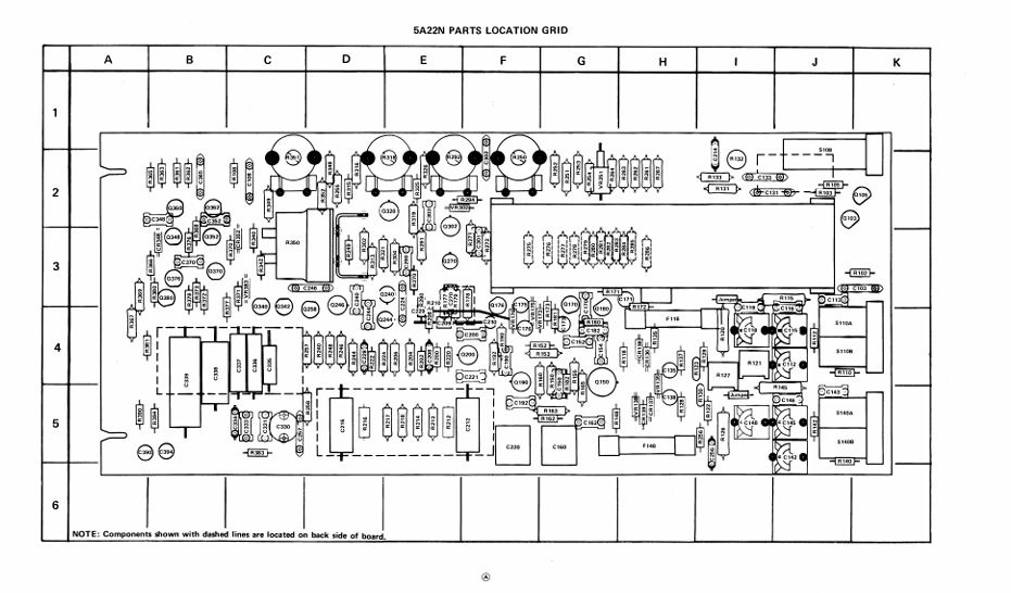
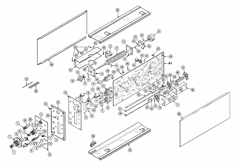
Drawings and Parts List (Section 4)
1. Symbols and reference identification rules
Component symbol: Following ANSI Y32.2-1970 standard, logical symbol follows MIL-STD-806B (positive logic);
Reference identification prefixes: C=capacitor, R=resistor, Q=transistor, CR=diode, F=fuse, J=fixed connector, S=switch, VR=voltage regulator (transistor), etc.
2. Core Parts List (Example)
Part Type Reference Identification Tektronix Part Number Specification Description
Capacitor C103 283-0002-00 0.01pF, ceramic, 500V
Capacitor C133 283-0626-00 1800pF, mica, 5%
Resistance R120 322-0481-07 1M Ω, 1/4W, 1/10%
Resistance R121 311-1223-00 250 Ω, variable
Transistors Q150A/B 151-1027-00 silicon FET, replaceable with D/2N4394 or FD1392
Transistors Q103/Q105 151-0347-00 silicon NPN, replaceable with 2N5551
Diode VR138 152-0520-00 Zener diode, 1W, 12V, replaceable with UZ8712 or HW12B
Switch A10 (LF-3dB) 105-0310-00 cam switch
Switch S280 (VOLTS/DIV) 105-0309-00 cam switch
Circuit board A1 670-1894-00 main circuit board component
- OMRON
- ABB
- General Electric
- EMERSON
- Honeywell
- HIMA
- ALSTOM
- Rolls-Royce
- MOTOROLA
- Rockwell
- Siemens
- Woodward
- YOKOGAWA
- FOXBORO
- KOLLMORGEN
- MOOG
- KB
- YAMAHA
- BENDER
- TEKTRONIX
- Westinghouse
- AMAT
- AB
- XYCOM
- Yaskawa
- B&R
- Schneider
- KONGSBERG
- NI
- WATLOW
- ProSoft
- SEW
- ADVANCED
- Reliance
- TRICONEX
- METSO
- MAN
- Advantest
- STUDER
- DANAHER MOTION
- Bently
- Galil
- EATON
- MOLEX
- DEIF
- B&W
- ZYGO
- Aerotech
- DANFOSS
- Beijer
- Moxa
- Rexroth
- Johnson
- WAGO
- TOSHIBA
- BMCM
- SMC
- HITACHI
- HIRSCHMANN
- Application field
- XP POWER
- CTI
- TRICON
- STOBER
- Thinklogical
- Horner Automation
- Meggitt
- Fanuc
- Baldor
- SHINKAWA
- Other Brands
- UniOP
- KUKA
- Iba
- Beckhoff
-
 Basler SR32A2B05B3E Static Voltage Regulator
 -
 Basler Electric BE1-59N Ground Fault Overvoltage Relay
 -
 Basler Electric 9110000113 Excitation Module
 -
 Basler Electric 90-72300-114 Control Accessory
 -
 Basler Electric PRS-250 Protection Relay System
 -
Basler Electric BE1-50/51M-109 Overcurrent Relay
-
 Basler Electric SR4A1B10B3E Static Voltage Regulator
 -
 Basler Electric CBS 212 Current Boost System
 -
Basler Electric SR32A2B05B3E Static Voltage Regulator
-
Basler Electric MOC2207 Motor Operated Potentiometer
-
 Basler Electric SR4A1B05A3E Static Voltage Regulator
 -
 Basler Electric BE1-32R Power Relay B2EE1PA0N1F
 -
Basler BEI-81 Underfrequency Relay
-
Basler CBS 212A Current Boost System
-
 Basler SSR 63-12 Static Voltage Regulator
 -
 Basler DGC-2020 Digital Genset Controller
 -
Basler BE1-32 Reverse Power Relay
-
 Basler BE1-50/51B-207 Overcurrent Relay
 -
 Basler BE1-951 Overcurrent Protection System
 -
 Basler 9073800-103 Power Supply
 -
 Basler SCA1300-32FC CCD Camera
 -
Basler 9073800-103 Power Supply
-
Basler SCA1300-32FC CCD Camera
-
 Basler L304KC Protective Relay
 -
 Basler BE3-25-1S1N4 Time Overcurrent Relay
 -
 Basler 9032300113 Excitation Support System
 -
 Basler BE1-59N Ground Overvoltage Relay
 -
 Basler MVC-300 Manual Voltage Control Unit
 -
 Basler MOC2102 Potentiometer
 -
 Basler BE1-87G Generator Differential Relay
 -
 Basler Electric DECS-200 Digital Excitation Control System
 -
Basler Electric DECS 125-15-B2C5 Digital Excitation System
-
 Basler Electric PLA2400-12GM Power Supply
 -
 Basler Electric BE1-50/51B-235 Overcurrent Relay
 -
Basler Electric BE1-27/59 Undervoltage Overvoltage Relay
-
 Basler Electric CEM-2020 Contact Expansion Module
 -
 Basler Electric BE1-32R Solid State Power Relay
 -
 Basler Electric BE1-700 Digital Generator Management Relay
 -
Basler Electric BE1-59N Ground Fault Overvoltage Relay
-
 Basler Electric BE10493002 Protection Module
 -
 Basler Electric BEI-79A1AA5CA3M1F Digital Annunciator
 -
 Basler Electric SSR 32-12 Static Voltage Regulator
 -
Basler Electric BE1-CDS240 Current Differential System
-
Basler Electric BE1-67 Directional Overcurrent Relay
-
 Basler Electric 9121000106 DECS-100 Voltage Controller
 -
Basler Electric BEI-871 Interface Module
-
 Basler Electric 8650C72 Exciter Control Module
 -
 Basler Electric RDP-110-S1 Generator Annunciator
 -
Basler Electric BE1-32O/U Directional Power Relay
-
 Basler Electric BE2000E AVR Voltage Regulator
 -
BASLER ELECTRIC BE1-50F2EA1PA0N0F Instantaneous Overcurrent Relay
-
BASLER ELECTRIC BE1-81T1EE1WA0N1F Underfrequency Relay
-
Basler BE1-67 Directional Overcurrent Relay
-
Basler BE1-25/79TR Reclosing Relay
-
Basler CEM-2020 Contact Expansion Module
-
Basler BE1-11 Overcurrent Protection Relay
-
 Basler BE1-GPS Generator Protective Relay
 -
 BASLER ELECTRIC MVC-300 MANUAL VOLTAGE CONTROL UNIT 9121000106
 -
 Basler Electric KR2FF Voltage Regulator 9 1163 00 109
 -
 BASLER ELECTRIC BE1-87G-G1E-A1K-A0N0F Generator Differential Relay
 -
 Basler BE1-47NE3EA1PA0N2F Phase Sequence Relay
 -
 Basler BE1-81-T1E-E1C-B0N1F Frequency Relay
 -
Basler DECS125-15 Excitation Control
-
Basler BE1-25 Sync-Check Relay
-
 Basler BE1-50/51B Overcurrent Relay
 -
Basler BE1-40Q Loss of Excitation Relay
-
 Basler BE1-50/51M-104 Overcurrent Relay
 -
Basler SSE-N 250-9 KW Shunt Exciter Assembly
-
Basler BE1-87T Transformer Differential Relay
-
 Basler BE1-60 Solid State Protective Relay
 -
Basler DECS125-15 Excitation Control System
-
Basler SR4A-2B15B3A Static Voltage Regulator
-
 Basler BE150BF Overcurrent Relay
 -
 BASLER ELECTRIC BE1A1HF1JD1S2F Overcurrent Relay
 -
Basler BE1-81O Under/Over Frequency Relay
-
 Basler EDM-200 Exciter Diode Monitor
 -
 Basler DECS125-15-B2C5 Excitation Control
 -
 Basler 9261402100 PCB Board
 -
Basler 9252000107 Overcurrent Relay
-
Basler BE1-87T Solid State Protective Relay
-
Basler Electric Phase Directional Overcurrent Relay BE1-Z2JA0N2F
-
 Basler SSR125-12 Static Voltage Regulator
 -
 Basler Electric KR7F VOLTAGE REGULATOR 9116200100
 -
BASLER ELECTRIC BE1-59N-A8E-E1L-N0S1F Ground Overvoltage Relay
-
 Basler SR8A2B06B3A Static Voltage Regulator
 -
BASLER ELECTRIC BE1-81O/UT3EE1KA7N1F Under/Over Frequency Relay
-
 Basler MOC2107 Output Module
 -
 Basler 9125600102 Control Module
 -
 BASLER ELECTRIC BE1-81T1EE1EA2N0F
 -
 Basler BE3-25A Time Overcurrent Relay
 -
Basler Electric CBS 212 Current Boost System 9 2650 00 100 120/240 VAC 50/60Hz
-
Basler Electric BE1-27 Under Voltage Relay A3EC1JA0N5F
-
 Basler BE1-32R Power Relay B2EE1PA0N1F
 -
 Basler DECS100-B15 Automatic Voltage Regulator
 -
 Basler SR8A-2B15B3A Static Voltage Regulator
 -
 Basler AVC63-4 Analog Voltage Regulator
 -
 Basler UFOV 260 A Overvoltage Module
 -
 Basler SR4A-2B16B3A Static Voltage Regulator
 -
Basler SR4A-2B16B3E Static Voltage Regulator
-
Basler SCA1300-32GM CCD Camera
-
 Basler BE34062001 G18 Transformer
 -
Basler BE1-87T Transformer Differential Relay
-
 Basler 9 2849 00 101 DECS Power Module
 -
 Basler RAL6144-16GM Line Scan Camera
 -
 Basler 9269101107 Voltage Regulator Board
 -
Basler BE1-851 Overcurrent Relay
-
Basler SR32A-2B13B3E Static Voltage Regulator
-
 Basler 9 2007 00 100 Current Boost System CBS 305
 -
Basler DECS-100-B11 Automatic Voltage Regulator
-
 Basler BE127 Under Voltage Relay
 -
 Basler 3300C03B1028-G01 Spike Suppressor
 -
Basler SSR 125-12 Static Voltage Regulator
-
Basler SCA1300-32GM CCD Camera Lens Enclosure
-
 Basler BE32965001 Transformer Timer Kit
 -
Basler D90 96801 100 PCB Card
-
 Basler BE1-81-T1E-E1C-A0N1F / 9106400 Underfrequency Relay
 -
 Pro-Face Basler AGP3600-T1-D24 HMI Touch
 -
Basler SR4A2B10B1A Static Voltage Regulator
-
Basler SR8A2B05B3A Static Voltage Regulator
-
Basler BE1-25 Time Overcurrent Relay M1FA6PA4S0F
-
Basler SR4A2B05B3E Static Voltage Regulator
-
 Basler DECS-200-2L Digital Excitation Control
 -
 Basler BE303280001 Control Transformer
 -
Basler 9262103004 Voltage Regulator Board For Basler DECS-400
-
 Basler ICRM-7 Inrush Current Reduction Module
 -
Basler BE1-32R Power Relay
-
BASLER ELECTRIC KR4F VOLTAGE REGULATOR 9042600100 600V 50/60Hz
-
Basler 9222600101 Power Module


