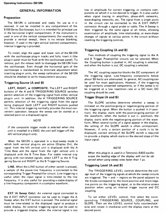
TEKTRONIX 5B12N Dual Time Base Plugin
Scanning speed range:
A time base: 1 μ s/Div to 5s/Div (21 levels 1-2-5 sequence), 10x magnification (A SWP MAG) to reach 100ns/Div;
B time base: 0.2 μ s/Div to 0.5s/Div (20 levels 1-2-5 sequence), no amplification function.
Delay function: Set the delay time using the DELAY TIME MULT knob, with a range of 0.2-10.2 times the A time base sweep speed (corresponding to 1 μ s to 50s), for delayed sweep mode.
External signal support: External signals can be connected to replace the A time base display, and the amplifier mode provides two calibration deflection coefficients of 50mV/Div and 0.5V/Div.
2. Set A Seconds/DIV (delay benchmark) and DELAY TIME MULT (delay multiplier)
3. Adjust the B Seconds/DIV (delayed sweep speed) to be faster than the A time base to avoid logic errors
2. Sweep frequency amplification operation (taking 100x amplification as an example)
Preparation for dual sweep mode: Press the A+B button, connect the left/right vertical plugs to the same signal, set A Seconds/DIV to 0.1ms/Div (display complete waveform);
Delay mode start: Press A INTEN-B DLY'D and use DELAY TIME MULT to locate the enhanced segment to the pulse that needs to be amplified;
B time base setting: B Seconds/DIV is set to 1 μ s/Div (1/100 of A scan speed), and at this time B time base displays a 100x amplified waveform of A time base enhancement segment;
Calculate magnification factor:
Magnification factor=B Seconds/DIV settings
A Seconds/DIV setting= 1×10 −60.1×10 −3=100
Application scenarios and examples
1. Time difference measurement (interval between two pulses)
Signal access: The left/right vertical plug-in is connected to a signal containing two pulses, in dual sweep mode (A+B pressed), with Volts/Div set to 2 grid amplitudes;
A Time Base Setting: A Seconds/DIV is set to 0.2m/Div (displaying the multi grid distance between two pulses), and the trigger parameter is adjusted to stable display (using CHOP mode for slow scanning speed);
Delay mode start: Press A INTEN-B DLY'D, set B Seconds/DIV to 2 μ s/Div (1/100 of A scan speed), and strengthen the segment length by about 0.1 grid;
Delay positioning: DELAY TIME MULT first locates the rising edge of the first pulse (reading 1.31), and then locates the second pulse (reading 8.81);
Calculate time difference:
Time difference=(8.81-1.31) × 0.2ms=1.5ms
.2. Pulse jitter measurement
Signal access: Left/right vertical plug-in access pulse signal, dual sweep frequency mode, Volts/Div set to 4 grid amplitude;
A Time Base Setting: A Seconds/DIV is set to display the complete waveform, and the trigger parameters are adjusted to stability;
Delay mode start: Press A INTEN-B DLY'D, DELAY TIME MULT locate the pulse to be tested, and set B Seconds/DIV to 0.2 μ s/Div (covering the pulse front);
Jitter calculation: observe the horizontal offset of the pulse in the B time base (example 0.5 grid),
Jitter=0.5 × 0.2 μ s=0.1 μ s
Electrical characteristics (core parameters)
Specific parameter accuracy/range for characteristic category
A time base scanning speed calibration range: 1 μ s/Div-5s/Div (21 levels); 100ns/Div 1 μ s/Div-1s/Div after 10x magnification: ± 3%; 2s/Div-5s/Div:±4%; Enlarged+1%
Non calibrated range: continuously adjustable, extending up to 12.5/s Div-
B time base scanning speed calibration range: 0.2 μ s/Div-0.5s/Div (20 levels) 1 μ s/Div-0.1s/Div: ± 3%; 0.2 μ s/Div, 0.5 μ s/Div, 0.2 s/Div, 0.5 s/Div: ± 4%
Delay characteristics: Delay multiple: 0.2-10.2 times A time base scanning speed (1 μ s-50s) 1 μ s/Div-0.5s/Div: ± 1%; 1s/Div-5s/Div:±2%
Inherent latency: ≤ 500ns-
Delay jitter: ≤ 1/20000 × 10x A time base scanning speed-
Trigger characteristic internal trigger (DC coupling): ≥ 0.4 grid (DC-1MHz); ≥ 0.6 grid (2MHz)-
External trigger (A time base): ≥ 200mV (DC-2MHz) Input RC: 1M Ω± 2%//70pF
Maximum safe input voltage: 350V (DC+peak AC)-
Amplifier mode deflection coefficient: 50mV/Div, 0.5V/Div ± 3%
Bandwidth: DC - ≥ 1MHz (AC coupling 50Hz - ≥ 1MHz)-
Non calibration range: ≥ 10:1 attenuation-

- ABB
- General Electric
- EMERSON
- Honeywell
- HIMA
- ALSTOM
- Rolls-Royce
- MOTOROLA
- Rockwell
- Siemens
- Woodward
- YOKOGAWA
- FOXBORO
- KOLLMORGEN
- MOOG
- KB
- YAMAHA
- BENDER
- TEKTRONIX
- Westinghouse
- AMAT
- AB
- XYCOM
- Yaskawa
- B&R
- Schneider
- Kongsberg
- NI
- WATLOW
- ProSoft
- SEW
- ADVANCED
- Reliance
- TRICONEX
- METSO
- MAN
- Advantest
- STUDER
- KONGSBERG
- DANAHER MOTION
- Bently
- Galil
- EATON
- MOLEX
- DEIF
- B&W
- ZYGO
- Aerotech
- DANFOSS
- Beijer
- Moxa
- Rexroth
- Johnson
- WAGO
- TOSHIBA
- BMCM
- SMC
- HITACHI
- HIRSCHMANN
- Application field
- XP POWER
- CTI
- TRICON
- STOBER
- Thinklogical
- Horner Automation
- Meggitt
- Fanuc
- Baldor
- SHINKAWA
- Other Brands


