
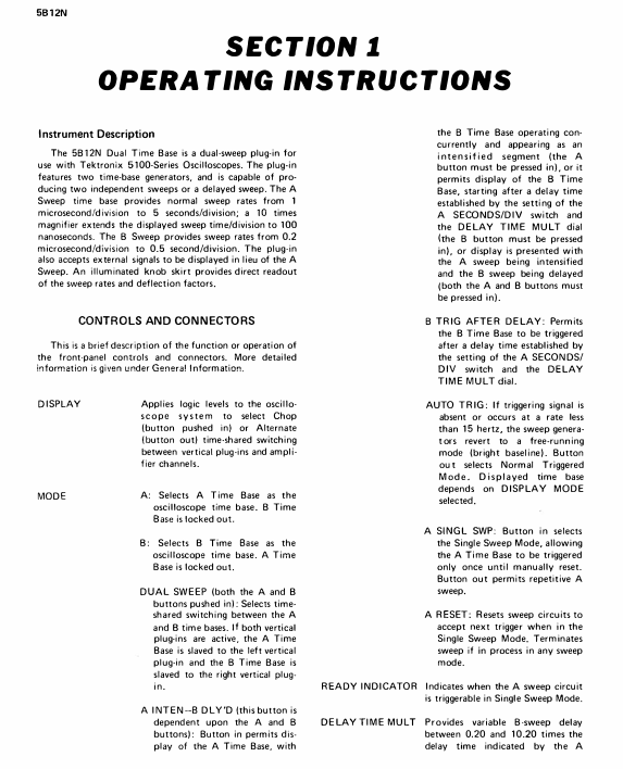
TEKTRONIX 5B12N Dual Time Base Plugin
Scanning speed range:
A time base: 1 μ s/Div to 5s/Div (21 levels 1-2-5 sequence), 10x magnification (A SWP MAG) to reach 100ns/Div;
B time base: 0.2 μ s/Div to 0.5s/Div (20 levels 1-2-5 sequence), no amplification function.
Delay function: Set the delay time using the DELAY TIME MULT knob, with a range of 0.2-10.2 times the A time base sweep speed (corresponding to 1 μ s to 50s), for delayed sweep mode.
External signal support: External signals can be connected to replace the A time base display, and the amplifier mode provides two calibration deflection coefficients of 50mV/Div and 0.5V/Div.
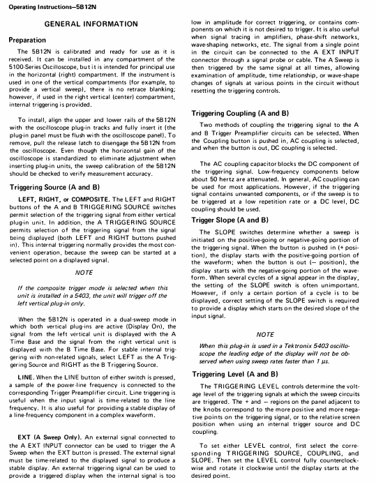
TEKTRONIX 5B12N Dual Time Base Plugin
Core characteristics of the instrument and panel controls
1. Core characteristics of the instrument
Dual time base generator: including A time base (main time base) and B time base (auxiliary time base), supporting three working modes (independent sweep, dual sweep, delayed sweep).
Scanning speed range:
A time base: 1 μ s/Div to 5s/Div (21 levels 1-2-5 sequence), 10x magnification (A SWP MAG) to reach 100ns/Div;
B time base: 0.2 μ s/Div to 0.5s/Div (20 levels 1-2-5 sequence), no amplification function.
Delay function: Set the delay time using the DELAY TIME MULT knob, with a range of 0.2-10.2 times the A time base sweep speed (corresponding to 1 μ s to 50s), for delayed sweep mode.
External signal support: External signals can be connected to replace the A time base display, and the amplifier mode provides two calibration deflection coefficients of 50mV/Div and 0.5V/Div.
2. Key panel controls (function summary)
Control Category Control Name Function Description
Mode control MODE (A/B/dual sweep) - A: Only A time base works, B time base is locked
-B: Only B time base works, A time base is locked
-Dual sweep frequency (A+B pressed): A and B time bases work simultaneously, with time sharing display
A INTEN-B DLY'D Delay Sweep Mode Switch, to be coordinated with A/B buttons:
-Only press A: display A time base, B time base works synchronously (strengthened segment display)
-Only press B: B time base delay start (delay time is determined by A time base and DELAY TIME MULT)
-Press A+B: A time base strengthening segment and B time base delay display
B TRIG AFTER DLY is triggered after a delay in the B time base. It is necessary to first meet the delay time set by the A time base, and then activate the B time base with the trigger signal
Time base control A/B Seconds/DIV selects calibration scanning speed, and the knob skirt lights up to display the current gear (A is a dark gray knob, B is a light gray knob)
A SWP MAG A time base is amplified 10 times, and the scanning speed is directly displayed after amplification (such as 1 μ s/Div → 100ns/Div), with only the central grid area visible
DELAY TIME MULT delay multiple adjustment, range 0.2-10.2 times A time base sweep speed, used to locate the starting point of delayed sweep frequency
A SINGL SWP A Time Base Single Sweep Mode, only triggered once when pressed, requires A RESET reset
A RESET resets the sweep circuit: re standby in single mode, terminate the current sweep in any mode
Trigger Control A/B TRIGGERING Source - LEFT/RIGHT: Select the left/right vertical plugin as the trigger source
-COMPOSITE (exclusive to A): Select the display signal as the trigger source (press A+B)
-LINE: Select the power frequency (50/60Hz) as the trigger source
-EXT (unique to A): Select A EXT INPUT external signal as the trigger source
A/B TRIGGERING COUPLING - AC (pressed): Capacitive coupling, blocking DC, attenuating low frequencies<50Hz
-DC (pop-up): Direct coupling, retaining DC and low-frequency components
A/B TRIGGERING SLOPE -+SLOPE (pressed): Positive slope trigger (signal rising edge starts sweep frequency)
-- SLOPE (pop-up): Negative slope trigger (signal falling edge initiates frequency sweep)
A/B TRIGGERING LEVEL adjusts the trigger level, and the ± region corresponds to the positive and negative voltage points of the signal. Rotate clockwise to increase the trigger level
Status and display READY INDICATOR indicator light, illuminated in A time base single mode to indicate readiness (trigger acceptable)
Display (ALT/CHOP) - ALT (pop-up): alternately displays A/B time base, suitable for fast scanning speed
-CHOP (pressed): Chopper displays A/B time base, suitable for scenarios with slow scanning speed or large scanning speed differences
INTEN BAL balances the brightness of A and B time base trajectories for clear observation or photography in dual sweep mode
Working mode and operation process
1. Three core working modes
Mode name trigger condition applicable scenario key operation steps
Independent sweep mode (A or B works separately) - Normal trigger (AUTO TRIG pops up): The trigger signal must be ≥ 15Hz and the LEVEL must be correct
-Automatic trigger (AUTO TRIG pressed): Free operation at<15Hz or no trigger (baseline illuminated)
-Single trigger (A SINGL SWP pressed): Only 1 sweep frequency, A RESET is required to reset the regular time measurement of simple signals, non repetitive signal photography 1. Press the A or B button of MODE
2. Choose TRIGGERING SOURCE-COUPLING/SLOPE
3. Adjust LEVEL to stable display, press A RESET for standby in single mode
Dual sweep mode (A+B working simultaneously) A trigger source corresponds to the left vertical plugin, B trigger source corresponds to the right vertical plugin, and trigger parameters need to be set separately to observe two signals (or different scan speeds of the same signal) simultaneously. 1. Press the A+B button of MODE
2. Set the PLAY to ALT (fast scanning speed) or CHOP (slow scanning speed)
3. Adjust the Seconds/DIV and trigger parameters of A/B separately, and use INTERN BAL to balance the brightness
Delay sweep mode (B time base delay start): After triggering A time base, start B time base (or wait for triggering after B time base delay) signal local amplification, time difference measurement, pulse jitter measurement. 1. Press the A INTEN-B DLY'D button of MODE (in conjunction with A/B)
2. Set A Seconds/DIV (delay benchmark) and DELAY TIME MULT (delay multiplier)
3. Adjust the B Seconds/DIV (delayed sweep speed) to be faster than the A time base to avoid logic errors
2. Sweep frequency amplification operation (taking 100x amplification as an example)
Preparation for dual sweep mode: Press the A+B button, connect the left/right vertical plugs to the same signal, set A Seconds/DIV to 0.1ms/Div (display complete waveform);
Delay mode start: Press A INTEN-B DLY'D and use DELAY TIME MULT to locate the enhanced segment to the pulse that needs to be amplified;
B time base setting: B Seconds/DIV is set to 1 μ s/Div (1/100 of A scan speed), and at this time B time base displays a 100x amplified waveform of A time base enhancement segment;
Calculate magnification factor:
Magnification factor=B Seconds/DIV settings
A Seconds/DIV setting= 1×10 −60.1×10 −3=100
Application scenarios and examples
1. Time difference measurement (interval between two pulses)
Signal access: The left/right vertical plug-in is connected to a signal containing two pulses, in dual sweep mode (A+B pressed), with Volts/Div set to 2 grid amplitudes;
A Time Base Setting: A Seconds/DIV is set to 0.2m/Div (displaying the multi grid distance between two pulses), and the trigger parameter is adjusted to stable display (using CHOP mode for slow scanning speed);
Delay mode start: Press A INTEN-B DLY'D, set B Seconds/DIV to 2 μ s/Div (1/100 of A scan speed), and strengthen the segment length by about 0.1 grid;
Delay positioning: DELAY TIME MULT first locates the rising edge of the first pulse (reading 1.31), and then locates the second pulse (reading 8.81);
Calculate time difference:
Time difference=(8.81-1.31) × 0.2ms=1.5ms
.2. Pulse jitter measurement
Signal access: Left/right vertical plug-in access pulse signal, dual sweep frequency mode, Volts/Div set to 4 grid amplitude;
A Time Base Setting: A Seconds/DIV is set to display the complete waveform, and the trigger parameters are adjusted to stability;
Delay mode start: Press A INTEN-B DLY'D, DELAY TIME MULT locate the pulse to be tested, and set B Seconds/DIV to 0.2 μ s/Div (covering the pulse front);
Jitter calculation: observe the horizontal offset of the pulse in the B time base (example 0.5 grid),
Jitter=0.5 × 0.2 μ s=0.1 μ s
Electrical characteristics (core parameters)
Specific parameter accuracy/range for characteristic category
A time base scanning speed calibration range: 1 μ s/Div-5s/Div (21 levels); 100ns/Div 1 μ s/Div-1s/Div after 10x magnification: ± 3%; 2s/Div-5s/Div:±4%; Enlarged+1%
Non calibrated range: continuously adjustable, extending up to 12.5/s Div-
B time base scanning speed calibration range: 0.2 μ s/Div-0.5s/Div (20 levels) 1 μ s/Div-0.1s/Div: ± 3%; 0.2 μ s/Div, 0.5 μ s/Div, 0.2 s/Div, 0.5 s/Div: ± 4%
Delay characteristics: Delay multiple: 0.2-10.2 times A time base scanning speed (1 μ s-50s) 1 μ s/Div-0.5s/Div: ± 1%; 1s/Div-5s/Div:±2%
Inherent latency: ≤ 500ns-
Delay jitter: ≤ 1/20000 × 10x A time base scanning speed-
Trigger characteristic internal trigger (DC coupling): ≥ 0.4 grid (DC-1MHz); ≥ 0.6 grid (2MHz)-
External trigger (A time base): ≥ 200mV (DC-2MHz) Input RC: 1M Ω± 2%//70pF
Maximum safe input voltage: 350V (DC+peak AC)-
Amplifier mode deflection coefficient: 50mV/Div, 0.5V/Div ± 3%
Bandwidth: DC - ≥ 1MHz (AC coupling 50Hz - ≥ 1MHz)-
Non calibration range: ≥ 10:1 attenuation-
- OMRON
- ABB
- General Electric
- EMERSON
- Honeywell
- HIMA
- ALSTOM
- Rolls-Royce
- MOTOROLA
- Rockwell
- Siemens
- Woodward
- YOKOGAWA
- FOXBORO
- KOLLMORGEN
- MOOG
- KB
- YAMAHA
- BENDER
- TEKTRONIX
- Westinghouse
- AMAT
- AB
- XYCOM
- Yaskawa
- B&R
- Schneider
- KONGSBERG
- NI
- WATLOW
- ProSoft
- SEW
- ADVANCED
- Reliance
- TRICONEX
- METSO
- MAN
- Advantest
- STUDER
- DANAHER MOTION
- Bently
- Galil
- EATON
- MOLEX
- DEIF
- B&W
- ZYGO
- Aerotech
- DANFOSS
- Beijer
- Moxa
- Rexroth
- Johnson
- WAGO
- TOSHIBA
- BMCM
- SMC
- HITACHI
- HIRSCHMANN
- Application field
- XP POWER
- CTI
- TRICON
- STOBER
- Thinklogical
- Horner Automation
- Meggitt
- Fanuc
- Baldor
- SHINKAWA
- Other Brands
- UniOP
- KUKA
- Iba
- Beckhoff
-
 Basler SR32A2B05B3E Static Voltage Regulator
 -
 Basler Electric BE1-59N Ground Fault Overvoltage Relay
 -
 Basler Electric 9110000113 Excitation Module
 -
 Basler Electric 90-72300-114 Control Accessory
 -
 Basler Electric PRS-250 Protection Relay System
 -
Basler Electric BE1-50/51M-109 Overcurrent Relay
-
 Basler Electric SR4A1B10B3E Static Voltage Regulator
 -
 Basler Electric CBS 212 Current Boost System
 -
Basler Electric SR32A2B05B3E Static Voltage Regulator
-
Basler Electric MOC2207 Motor Operated Potentiometer
-
 Basler Electric SR4A1B05A3E Static Voltage Regulator
 -
 Basler Electric BE1-32R Power Relay B2EE1PA0N1F
 -
Basler BEI-81 Underfrequency Relay
-
Basler CBS 212A Current Boost System
-
 Basler SSR 63-12 Static Voltage Regulator
 -
 Basler DGC-2020 Digital Genset Controller
 -
Basler BE1-32 Reverse Power Relay
-
 Basler BE1-50/51B-207 Overcurrent Relay
 -
 Basler BE1-951 Overcurrent Protection System
 -
 Basler 9073800-103 Power Supply
 -
 Basler SCA1300-32FC CCD Camera
 -
Basler 9073800-103 Power Supply
-
Basler SCA1300-32FC CCD Camera
-
 Basler L304KC Protective Relay
 -
 Basler BE3-25-1S1N4 Time Overcurrent Relay
 -
 Basler 9032300113 Excitation Support System
 -
 Basler BE1-59N Ground Overvoltage Relay
 -
 Basler MVC-300 Manual Voltage Control Unit
 -
 Basler MOC2102 Potentiometer
 -
 Basler BE1-87G Generator Differential Relay
 -
 Basler Electric DECS-200 Digital Excitation Control System
 -
Basler Electric DECS 125-15-B2C5 Digital Excitation System
-
 Basler Electric PLA2400-12GM Power Supply
 -
 Basler Electric BE1-50/51B-235 Overcurrent Relay
 -
Basler Electric BE1-27/59 Undervoltage Overvoltage Relay
-
 Basler Electric CEM-2020 Contact Expansion Module
 -
 Basler Electric BE1-32R Solid State Power Relay
 -
 Basler Electric BE1-700 Digital Generator Management Relay
 -
Basler Electric BE1-59N Ground Fault Overvoltage Relay
-
 Basler Electric BE10493002 Protection Module
 -
 Basler Electric BEI-79A1AA5CA3M1F Digital Annunciator
 -
 Basler Electric SSR 32-12 Static Voltage Regulator
 -
Basler Electric BE1-CDS240 Current Differential System
-
Basler Electric BE1-67 Directional Overcurrent Relay
-
 Basler Electric 9121000106 DECS-100 Voltage Controller
 -
Basler Electric BEI-871 Interface Module
-
 Basler Electric 8650C72 Exciter Control Module
 -
 Basler Electric RDP-110-S1 Generator Annunciator
 -
Basler Electric BE1-32O/U Directional Power Relay
-
 Basler Electric BE2000E AVR Voltage Regulator
 -
BASLER ELECTRIC BE1-50F2EA1PA0N0F Instantaneous Overcurrent Relay
-
BASLER ELECTRIC BE1-81T1EE1WA0N1F Underfrequency Relay
-
Basler BE1-67 Directional Overcurrent Relay
-
Basler BE1-25/79TR Reclosing Relay
-
Basler CEM-2020 Contact Expansion Module
-
Basler BE1-11 Overcurrent Protection Relay
-
 Basler BE1-GPS Generator Protective Relay
 -
 BASLER ELECTRIC MVC-300 MANUAL VOLTAGE CONTROL UNIT 9121000106
 -
 Basler Electric KR2FF Voltage Regulator 9 1163 00 109
 -
 BASLER ELECTRIC BE1-87G-G1E-A1K-A0N0F Generator Differential Relay
 -
 Basler BE1-47NE3EA1PA0N2F Phase Sequence Relay
 -
 Basler BE1-81-T1E-E1C-B0N1F Frequency Relay
 -
Basler DECS125-15 Excitation Control
-
Basler BE1-25 Sync-Check Relay
-
 Basler BE1-50/51B Overcurrent Relay
 -
Basler BE1-40Q Loss of Excitation Relay
-
 Basler BE1-50/51M-104 Overcurrent Relay
 -
Basler SSE-N 250-9 KW Shunt Exciter Assembly
-
Basler BE1-87T Transformer Differential Relay
-
 Basler BE1-60 Solid State Protective Relay
 -
Basler DECS125-15 Excitation Control System
-
Basler SR4A-2B15B3A Static Voltage Regulator
-
 Basler BE150BF Overcurrent Relay
 -
 BASLER ELECTRIC BE1A1HF1JD1S2F Overcurrent Relay
 -
Basler BE1-81O Under/Over Frequency Relay
-
 Basler EDM-200 Exciter Diode Monitor
 -
 Basler DECS125-15-B2C5 Excitation Control
 -
 Basler 9261402100 PCB Board
 -
Basler 9252000107 Overcurrent Relay
-
Basler BE1-87T Solid State Protective Relay
-
Basler Electric Phase Directional Overcurrent Relay BE1-Z2JA0N2F
-
 Basler SSR125-12 Static Voltage Regulator
 -
 Basler Electric KR7F VOLTAGE REGULATOR 9116200100
 -
BASLER ELECTRIC BE1-59N-A8E-E1L-N0S1F Ground Overvoltage Relay
-
 Basler SR8A2B06B3A Static Voltage Regulator
 -
BASLER ELECTRIC BE1-81O/UT3EE1KA7N1F Under/Over Frequency Relay
-
 Basler MOC2107 Output Module
 -
 Basler 9125600102 Control Module
 -
 BASLER ELECTRIC BE1-81T1EE1EA2N0F
 -
 Basler BE3-25A Time Overcurrent Relay
 -
Basler Electric CBS 212 Current Boost System 9 2650 00 100 120/240 VAC 50/60Hz
-
Basler Electric BE1-27 Under Voltage Relay A3EC1JA0N5F
-
 Basler BE1-32R Power Relay B2EE1PA0N1F
 -
 Basler DECS100-B15 Automatic Voltage Regulator
 -
 Basler SR8A-2B15B3A Static Voltage Regulator
 -
 Basler AVC63-4 Analog Voltage Regulator
 -
 Basler UFOV 260 A Overvoltage Module
 -
 Basler SR4A-2B16B3A Static Voltage Regulator
 -
Basler SR4A-2B16B3E Static Voltage Regulator
-
Basler SCA1300-32GM CCD Camera
-
 Basler BE34062001 G18 Transformer
 -
Basler BE1-87T Transformer Differential Relay
-
 Basler 9 2849 00 101 DECS Power Module
 -
 Basler RAL6144-16GM Line Scan Camera
 -
 Basler 9269101107 Voltage Regulator Board
 -
Basler BE1-851 Overcurrent Relay
-
Basler SR32A-2B13B3E Static Voltage Regulator
-
 Basler 9 2007 00 100 Current Boost System CBS 305
 -
Basler DECS-100-B11 Automatic Voltage Regulator
-
 Basler BE127 Under Voltage Relay
 -
 Basler 3300C03B1028-G01 Spike Suppressor
 -
Basler SSR 125-12 Static Voltage Regulator
-
Basler SCA1300-32GM CCD Camera Lens Enclosure
-
 Basler BE32965001 Transformer Timer Kit
 -
Basler D90 96801 100 PCB Card
-
 Basler BE1-81-T1E-E1C-A0N1F / 9106400 Underfrequency Relay
 -
 Pro-Face Basler AGP3600-T1-D24 HMI Touch
 -
Basler SR4A2B10B1A Static Voltage Regulator
-
Basler SR8A2B05B3A Static Voltage Regulator
-
Basler BE1-25 Time Overcurrent Relay M1FA6PA4S0F
-
Basler SR4A2B05B3E Static Voltage Regulator
-
 Basler DECS-200-2L Digital Excitation Control
 -
 Basler BE303280001 Control Transformer
 -
Basler 9262103004 Voltage Regulator Board For Basler DECS-400
-
 Basler ICRM-7 Inrush Current Reduction Module
 -
Basler BE1-32R Power Relay
-
BASLER ELECTRIC KR4F VOLTAGE REGULATOR 9042600100 600V 50/60Hz
-
Basler 9222600101 Power Module


