
Yokogawa 701944/701945 100:1 High Voltage Probe
Yokogawa 701944/701945 100:1 High Voltage Probe
Document Overview
This document is the user manual for Yokogawa 701944 and 701945 models 100:1 high-voltage probes (8th edition, released in May 2024), which is primarily used to guide users in safely and correctly using this series of probes. It covers key content such as product usage, safety specifications, structural configuration, operating procedures, maintenance methods, and technical parameters. The content of the manual may change with product performance upgrades, and the latest version needs to be obtained through the official website. It also provides access to user registration, technical support contact information, and multilingual supporting documents (such as Chinese specific documents and European language safety manuals).
Safety regulations and symbol explanations
(1) Symbol rules
Warning symbols: including Warning (indicating operations and preventive measures that may cause serious or fatal injuries), CAUTION (indicating operations and preventive measures that may cause minor injuries or equipment damage), Note (indicating important information for correct equipment operation), and providing French translation instructions, suitable for multilingual usage scenarios.
Equipment symbol: The "manual reference required" symbol marked on the equipment indicates the need to consult the manual for special operating instructions to ensure that users do not miss key safety guidelines.
(2) Core Security Guidelines
Scope of use: The probe can only be used in conjunction with an oscilloscope for observing and measuring electrical signals. It is strictly prohibited to use it beyond the specified range; Measurement category II defined in accordance with IEC 61010-031 standard cannot be used for category III or IV scenarios. When combined with equipment/accessories of different measurement categories, the lower category shall prevail.
Grounding requirements: The protective grounding terminal of the oscilloscope must be grounded, and the grounding wire of the probe must be connected to the grounding potential. Double grounding can effectively prevent the risk of electric shock and ensure measurement safety.
Electric shock protection: It is strictly prohibited to operate with wet hands or use the probe when it is damp; Be cautious of electric shock when connecting the tested device, and do not remove the probe from the oscilloscope when connecting it to the tested device; Avoid contact with exposed circuits and remove metal jewelry such as watches and rings during operation to prevent accidental electric shock.
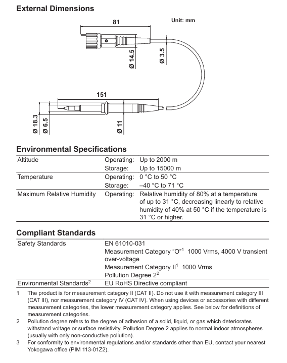
Environmental restrictions: Do not use in damp, dusty, or flammable/explosive environments to prevent equipment failure or safety accidents; In terms of altitude, the working altitude should not exceed 2000m, and the storage altitude should not exceed 15000m; the working temperature should be between 0-50 ℃, the storage temperature should be between -40~71 ℃, and the humidity should meet the linear decreasing requirement of 80% (≤ 31 ℃) to 40% (50 ℃) to avoid environmental factors affecting measurement accuracy or damaging equipment.
Equipment status: If there is suspicion of probe damage (such as torn signal cables or exposed internal metal), immediately stop using and contact the dealer for repair; It is strictly prohibited to disassemble or modify the probe. Yokogawa shall not be held responsible for any malfunctions caused by unauthorized modifications; Strict adherence to the maximum input voltage limit (1000 Vrms) is required. When the oscilloscope input is coupled to AC, the DC voltage input by the probe will be synchronously applied to the oscilloscope input, ensuring that it does not exceed the maximum input voltage of the oscilloscope.
Product Overview and Configuration
(1) Product Features
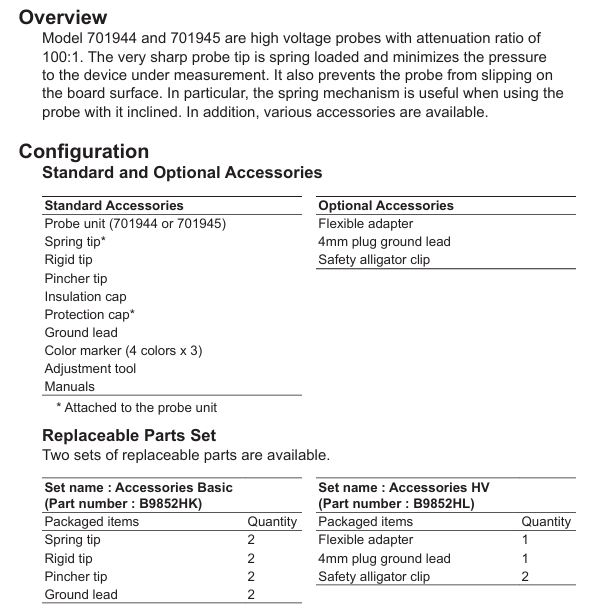
701944 and 701945 are both high-voltage probes with a 100:1 attenuation ratio, and their core advantages include:
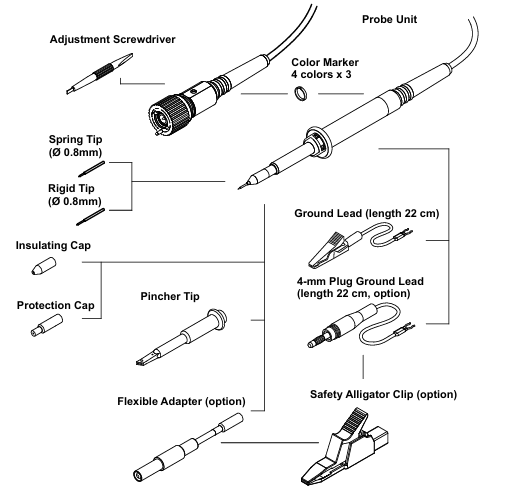
Probe tip design: Spring type tip (pre installed) can reduce pressure on the tested device, prevent sliding on the surface of the circuit board, and provide better stability when tilted for use; There are also options for rigid tips and clamp tips, suitable for different measurement scenarios.
Compatibility: Suitable for oscilloscopes with an input impedance of 1M Ω, the probe ID pin can be automatically recognized by the oscilloscope, and the oscilloscope attenuation ratio can be automatically set to 10:1 (manual adjustment is required if not automatically set).
Rich attachments: Provides a variety of standard and optional attachments to meet different measurement needs, and supports accessory replacement to extend the service life of the probe.
(2) Configuration List
Standard accessories: including probe body (701944/701945), spring tip (pre installed), rigid tip, clamp tip, insulation cap, protective cap (pre installed), grounding wire (22cm), color markings (4 colors x 3 pieces), adjustment tools and manual. All accessories must be confirmed complete and undamaged after unpacking to avoid affecting use.
Optional accessories: including flexible adapter, 4mm plug grounding wire, and safety crocodile clip, which need to be purchased separately and can be flexibly selected according to the measurement scenario.
Replacement accessory set: Two sets are available, "Accessories Basic" (B9852HK) including 2 spring tips, 2 rigid tips, 2 clamp tips, and 2 grounding wires; The "Accessories HV" (B9852HL) includes one flexible adapter, one 4mm plug grounding wire, and two safety crocodile clips, making it easy to replace accessories in bulk after wear and tear.
Operation process
(1) Basic Connection
Connection between probe and oscilloscope: Connect the BNC connector of the probe to the 1M Ω input port of the oscilloscope, ensuring that the input impedance of the oscilloscope is set to 1M Ω; the probe ID pin will be automatically recognized by the oscilloscope, and the attenuation ratio will be automatically set to 10:1. If it is not automatically set, it needs to be manually adjusted to the corresponding gear to ensure accurate measurement data.
Grounding connection: Connect the probe grounding wire to the grounding potential, which can only be used for grounding connection and cannot be used for other purposes; It is strictly prohibited to use non designated grounding wires to prevent measurement errors or safety risks caused by poor grounding.
(2) Calibration process
Low frequency compensation (LF Compensation): Connect the probe input to the probe compensation adjustment terminal (CAL/COMP terminal) of the oscilloscope, use the matching adjustment tool to rotate the low-frequency compensation micro adjuster, adjust the observed waveform to a standard square wave, ensure that the probe capacitance matches the oscilloscope input capacitance, and ensure measurement accuracy within the frequency range from DC to the upper limit of the bandwidth. Compensating for abnormalities (under compensation/over compensation) will cause waveform distortion and require readjustment.
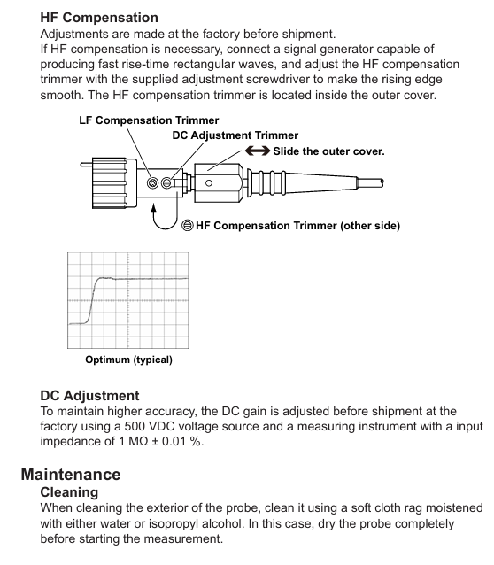
HF Compensation: Calibration has been completed before leaving the factory. If adjustment is needed, a signal generator that can generate a fast rising edge rectangular wave needs to be connected. Slide the probe housing to expose the high-frequency compensation micro adjuster, and use an adjustment tool to smooth the rising edge to ensure the accuracy of high-frequency signal measurement.
DC Adjustment: Before leaving the factory, a measuring instrument with a 500VDC voltage source and a 1M Ω± 0.01% input impedance is used for calibration. Users do not need to make routine adjustments. If high-precision measurement is required, they can contact the dealer for professional calibration.
(3) Precautions for using the probe
Tip replacement: When replacing the contact tip, it is necessary to clamp the tip with pliers and pull it out vertically along the axis of the probe. It is strictly prohibited to clamp the white plastic insulator or housing (to avoid damaging the probe); When inserting the new tip, align it with the socket along the axis and gently press it until it fully fits, ensuring good contact.
Cable protection: To prevent the probe body from being impacted, excessive bending or pulling of the cable is not allowed to prevent damage or breakage of internal circuits, which may affect signal transmission.
Voltage derating: When the input signal frequency increases, the maximum input voltage of the probe will decrease. It is necessary to refer to the "Voltage derating curve" to select the appropriate input voltage to avoid overvoltage damage to the probe; Pulse measurement must comply with the corresponding limitations of peak pulse voltage, duty cycle, and duration to ensure safe use.
Maintenance and disposal
(1) Daily maintenance
Cleaning: When cleaning the probe housing, only a soft cloth dipped in water or isopropanol can be used to wipe it. After wiping, it must be completely dry before it can be used for measurement. Volatile chemicals such as benzene and diluents should not be used to prevent corrosion or deformation of the housing.
Accessory inspection: Regularly check whether the probe tip, grounding wire, and cable are intact. If the tip is worn, the cable is cracked, or the grounding wire is aged, the corresponding accessories should be replaced in a timely manner to avoid affecting measurement accuracy or causing safety hazards.
(2) Disposal of waste
When discarding probes or accessories, it is necessary to comply with the laws and regulations of the country/region where they are located and not to dispose of them at will; Components belonging to electronic waste, such as probe bodies and cables, must be disposed of in accordance with local electronic waste disposal regulations to avoid environmental pollution and comply with the EU WEEE Directive and relevant environmental requirements of each country.
Technical parameters
(1) Electrical parameters
Parameter 701944 701945 Remarks
Attenuation ratio 100:1 ± 2% (DC) 100:1 ± 2% (DC) requires the connection of an oscilloscope with an input impedance of 1M Ω± 1%
The typical value of voltage coefficient is 0.0005%/V, which reflects the influence of voltage changes on the attenuation ratio. The smaller the coefficient, the higher the accuracy
When the system bandwidth is -3dB, an oscilloscope with a bandwidth ≥ 500MHz needs to be connected to 400MHz and 250MHz, otherwise it is limited by the oscilloscope bandwidth
When the rise time of the probe is 10%~90%, it is less than 900ps. When it is 10%~90%, it is less than 1.4ns. The shorter the rise time, the faster the high-frequency signal response
The maximum input voltage is 1000Vrms. The voltage derating curve should be referenced for 1000Vrms, and the input voltage should be reduced at high frequencies
System input resistance 50M Ω± 1% 50M Ω± 1% ensures matching with oscilloscope input impedance
The typical value of system input capacitance is 7.5pF, which affects the stability of high-frequency signal measurement
Compensation range typical value 10pF~25pF typical value 10pF~25pF adapted to different oscilloscope input capacitors
(2) Mechanical and environmental parameters
Weight: The probe body weighs about 55g, lightweight and easy to operate, reducing fatigue from prolonged use.
Cable length: 701944 is about 1.2m, 701945 is about 3m, suitable for different measurement distance requirements. The long cable model (701945) is more suitable for long-distance measurement scenarios.
Protection standard: Complies with EN 61010-031 safety standard, measurement category II, transient voltage 4000V; complies with the EU RoHS directive, environmentally friendly and free of harmful substances.
Input impedance characteristics: It decreases with the increase of input signal frequency, and reference should be made to the "input impedance curve". When measuring at high frequencies, attention should be paid to the impact of impedance changes on the measurement results.
- ABB
- General Electric
- EMERSON
- Honeywell
- HIMA
- ALSTOM
- Rolls-Royce
- MOTOROLA
- Rockwell
- Siemens
- Woodward
- YOKOGAWA
- FOXBORO
- KOLLMORGEN
- MOOG
- KB
- YAMAHA
- BENDER
- TEKTRONIX
- Westinghouse
- AMAT
- AB
- XYCOM
- Yaskawa
- B&R
- Schneider
- Kongsberg
- NI
- WATLOW
- ProSoft
- SEW
- ADVANCED
- Reliance
- TRICONEX
- METSO
- MAN
- Advantest
- STUDER
- KONGSBERG
- DANAHER MOTION
- Bently
- Galil
- EATON
- MOLEX
- DEIF
- B&W
- ZYGO
- Aerotech
- DANFOSS
- Beijer
- Moxa
- Rexroth
- Johnson
- WAGO
- TOSHIBA
- BMCM
- SMC
- HITACHI
- HIRSCHMANN
- Application field
- XP POWER
- CTI
- TRICON
- STOBER
- Thinklogical
- Horner Automation
- Meggitt
- Fanuc
- Baldor
- SHINKAWA
- Other Brands
- UniOP
- KUKA
- Iba
-
 ELAU DB-5 Distribution HW 5104 Servo System
 -
 Touchstar 10K TS10KCC0CEMP Industrial Touch Panel
 -
 Beckhoff CX2030-0125 Embedded PC PLC
 -
 Parker Hannifin HID5CS/S4 HIDRIVE 5A Servo Drive
 -
 Yaskawa ACE-P300-TH5 Servo Drive with Profibus
 -
 Omron Sysmac SCY-P0 13E Sequencer Controller
 -
 Saia Burgess PCD4.M120 PCD4.M12 Central Controller
 -
 Schneider Electric TSX3722101 Modicon Micro PLC
 -
 Siemens Micromaster 440 6SE6440-2AD25-5CA1 Inverter
 -
 SICK DL50-P1123 Distance Sensor
 -
 Yaskawa SGDH-04AE-OY Servo Driver 200V 400W
 -
 Cincinnati Milacron 3-542-1203A Circuit Board Module
 -
 Allen-Bradley 1756-EN2T EtherNet/IP Communication Module
 -
 OMRON CS1H-CPU66-V1 Programmable Logic Controller
 -
 ABB SACE TMAX S6N 630 Molded Case Circuit Breaker
 -
 Weidmuller IE-SW-VL16-16TX 16-Port Ethernet Switch
 -
 Schneider PowerLogic CM4250 Circuit Monitor
 -
 Sacmi IDPM IDMP1.A SMC 085.16.982 Control
 -
 Omron C120-LK202-EV1 Host Link Unit
 -
 Omron FQ2-S15050F Smart Camera Vision System
 -
 OMRON CJ1G-CPU44H Programmable Logic Controller
 -
 SIEMENS KTP600 HMI 6AV6 647-0AD11-3AX0 Touch Panel
 -
 OMRON CS1G-CPU45H EV1 Programmable Logic Controller
 -
 Omron C200HG PLC System C200H-ID212 C200H-OC226
 -
 ROBOSYSTEM IOG4AX-HD-100 IOG-HD Motion Controller
 -
 Datalogic SG4-S3-080-PP-W Safety Light Curtain
 -
 Omron NS12-TS01B-V2 Interactive Display
 -
 Esto Electronic E.CGT-405-42TE PLC Rack
 -
 Siemens 7ED62 Static Three Phase Counter
 -
 Oemer QCAVS 100 LBE AC Square Frame Servo Motor
 -
 Schneider Electric TM262M25MESS8T Motion Controller
 -
 Eaton Moeller MFD-CP8-ME Power Supply
 -
 Pro-face PL-5700T1-24VDC Industrial Panel PC
 -
 GE Fanuc IC693APU300J High Speed Counter
 -
 Fuji Electric Micrex-F FPU080S PLC Module
 -
 Automation Direct GS2-45P0 AC Drive
 -
 Omron 3G3MV-C4015 V1000 Inverter
 -
 Vacon NXI01055A2T0CSS Industrial Inverter
 -
 Saia Burgess PCD4.M240 Central Controller Module
 -
 Yaskawa SGDH-10DE Sigma II Servo Drive
 -
 Stober EK501USOM140 Servo Motor and Drive
 -
 SCE M68-2000/4 CNC Controller and I/O Board
 -
 Omron SP10-PR001-V1 PLC Programming Console Specs
 -
 VACON NXI01055A2T0CSSA Industrial AC Drive
 -
 OMRON SYSMAC SCY-P1 Sequencer Controller PLC
 -
 SEL-2440 DPAC Discrete Programmable Controller
 -
 BIVIATOR CI3098 CPU Encoder Module Industrial Control Unit
 -
 Siemens 6FC5371-0AA10-0AA2 SINUMERIK NCU 710.2
 -
 KOLLMORGEN SERVOSTAR S70601-NA High Performance Servo Drive
 -
 OMRON C200HW-PCU01 Fastnet PCMCIA LAN Communication Unit
 -
 ibaFOB-2io-D Two-Channel Fiber Optic Input Output Card
 -
 ibaFOB-4io-D Four-Channel Fiber Optic Input Output Card
 -
 ibaFOB-io-S Single-Channel Fiber Optic Input Output Card
 -
 ibaFOB-4io-S Four-Channel Fiber Optic Input Output Card
 -
 ibaFOB-4o Four-Channel Fiber Optic Output Interface Card
 -
 ibaFOB-4i-S Enhanced Four-Channel Fiber Optic Input Card
 -
 ibaFOB-4i Four-Channel Fiber Optic Input Interface Card
 -
 ibaFOB-io Fiber Optic Interface Card for iba Systems
 -
 SM128V VMEbus Interface Card for Industrial Data Acquisition
 -
 ibaLink-SM-128V-i-2o VMEbus Fiber Optic Interface Board
 -
 GE Fanuc IC693MDL632 125V DC Input Module 8 Points
 -
 GE Fanuc IC693MDL241 24V AC/VDC Input Module 16 Points
 -
 GE Fanuc IC693MDL240 120V AC Input Module 16 Points
 -
 GE Fanuc IC693MDL231 240V AC Isolated Input Module
 -
 GE Fanuc IC693MDL230 120V AC Isolated Input Module
 -
 GE Fanuc IC693MDL654 5/12 VDC 32-Point Input Module
 -
 GE Fanuc IC693MDL653 24 VDC 32-Point Input Module
 -
 GE Fanuc IC693MDL648 48 VDC 16-Point Input Module
 -
 GE Fanuc IC693MDL646 24 VDC 16-Point Input Module
 -
 GE Fanuc IC693MDL634 24 VDC Input Module 8 Points
 -
 GE IM 3100 D 1007722 Control Module
 -
 GE IM0146B Industrial Circuit Board
 -
 GE IM0059E0-10070 Interface Board
 -
 GE IM0094C Industrial Control Board
 -
 GE IC200PNS002-AB VersaMax PROFINET Scanner
 -
 GE F650BFBF1G0HI Feeder Protection Relay
 -
 GE TPR5616NRHC Protection Relay
 -
 GE D6P3KH Digital Protection Relay
 -
 GE F650BABF2G0HIS Feeder Protection Relay
 -
 GE F650BADF2G1HIR Feeder Protection Relay
 -
GE F650BABF2G1HI6 Digital Bay Controller
-
 GE Multilin 745-W2-P1-G1-H-I-A-R-E Transformer Protection Relay
 -
 GE 100BASE-T Industrial Ethernet Interface
 -
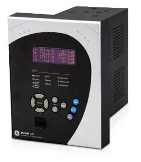 GE Multilin 350-E-P1-S1-H-S-E-C-N-2E-D-H Feeder Protection System
 -
 GE F650MXCF1G1HI6 Bay Controller
 -
 GE MM300-GEHD2CAB Motor Management Relay
 -
 GE MMS35-621-1-00 Motor Management System
 -
 GE 100BASE-T Ethernet Communication Module
 -
 GE F650MFCF1G1HI6 Feeder Protection Relay
 -
 GE CK13BA300 Control Module
 -
 GE W2-P1-G1-H Industrial Control Unit
 -
 GE PIB315B Power Interface Board
 -
 GE 343L695VAGIRHC Multi-Function Relay
 -
 GE Multilin B90N05HKHF8NH6 Bus Differential Protection
 -
 GE ZX3SC0204N-930 Intelligent Control Module
 -
 GE PIB504 Process Interface Board
 -
 GE D20MX Remote Terminal Unit
 -
 GE T60UJ3HKHF8NH6 Transformer Protection Relay
 -
 GE ZG3SA02041-58S600X Motor Protection Relay
 -
 GE ZG3SA02041-58S Motor Protection Relay
 -
 ABB DSDX 452 L Remote Input Output Module
 -
 ABB RDCU-02C Drive Control Unit
 -
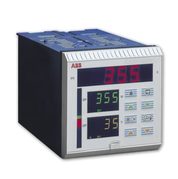 ABB COMMANDER 350 Process Controller
 -
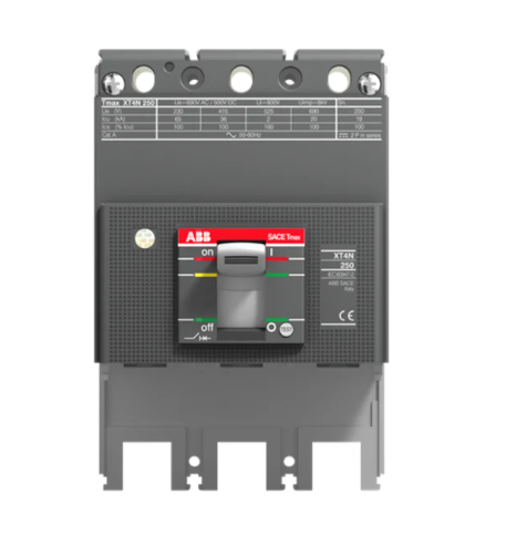 ABB Tmax XT4S 250 Molded Case Circuit Breaker
 -
 DEIF MALLING 8027.90 Industrial Control Unit
 -
 DEIF DCP2-2410 Power Supply Module
 -
 DEIF FAS-2N Synchronizer
 -
 DEIF MALLING 827.54 Processor Module
 -
 DEIF DU-2/MKIII Display Unit
 -
 DEIF DRW-2 Reverse Power Relay
 -
 DEIF 827.4 Power Management Module
 -
 DEIF 1044220060F Mains Measurement Module
 -
 DEIF 1044220190G Remote Display Module
 -
 DEIF 1044220140C AGC 200 Display Module
 -
 DEIF BRW-1-NB Remote Display Unit
 -
 DEIF MALLING 827.52 Industrial Control Unit for Automation Systems
 -
 DEIF BRW-2 Industrial Relay Module for Control Systems
 -
 DEIF 1044220080D Power System Control Module Industrial Automation
 -
 DEIF 1044220100F Controller Module for Generator Control Systems
 -
 DEIF DU-300 Voltage Monitoring Relay Industrial Protection Unit
 -
 DEIF 1044220060F I/O Extension Module
 -
 DEIF 1044220150C Interface Module
 -
 DEIF GCU 100 Engine Control Unit
 -
 DEIF XDI144-DUAL Marine Indicator
 -
 DEIF 827.41 Multi-line 2 Processor Module
 -
DEIF AGC 146 Automatic Genset Controller
-
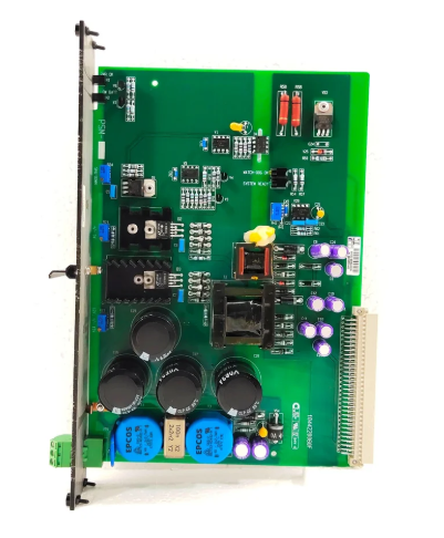
 DEIF 1044220080E MDR-2 Display Module
 -
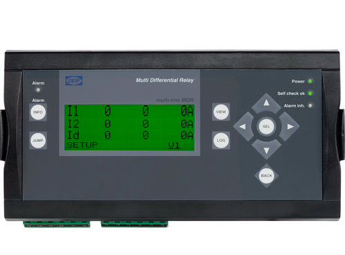 DEIF MDR-2 Multifunctional Digital Relay


