WAGO I/O System 750/753 Series Distributed Automation System
Applicable scenarios: Indoor dry environments in the field of industrial automation, suitable for ordinary industrial areas, and certified for special scenarios such as marine, nearshore, explosion-proof (Ex i), functional safety, etc.
Installation requirements: As an open device, it needs to be installed in an additional enclosure and operated by professional electrical personnel according to standards such as EN 50110-1/-2 and IEC 60364.
Encoding configuration: The 753 series module prevents accidental insertion by encoding the key (753-150), with 2 keys supporting 16 encoding combinations.
Dismantling process:
Power outage confirmation: Disconnect the system from the on-site power supply and verify that there is no voltage before operation.
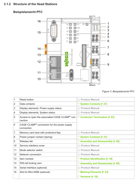
Head station disassembly: Unlock the locking cam with the tool, pull the release buckle to detach from the guide rail.
I/O module disassembly: 750 series, directly pull the orange release buckle; The 753 series first separates the wiring interface (pull the locking latch), and then pull the release buckle.
3. Wiring operation specifications
Conductor requirements:
Supports copper and aluminum conductors (aluminum conductors need to be cleaned and coated with "Alu Plus" contact paste), with only one conductor connected to a single clamping unit.
The cross-sectional area of the wire needs to match the current load, and larger cross-sectional conductors should be selected in high current scenarios to reduce temperature rise.
Wiring steps:
CAGE CLAMP ®: Insert the tool into the rectangular opening to open the fixture → Insert the conductor → Pull out the tool lock.
Push-in CAGE CLAMP ®: Direct insertion adapter conductor; Non compatible conductors require tools to be tilted and inserted into the opening after opening the fixture.
Special scenario application configuration
1. Marine and nearshore scenarios (DNV certified)
Classification requirements:
Class A: Suitable for non bridge and non outdoor deck areas; Class B: Suitable for the entire area (including the bridge and outdoor deck).
Power supply configuration:
A high isolation (HI) filtering module is required for 24VDC power supply: the 750-626 series is used for system power supply, and the 750-624 series is used for on-site power supply.
Isolation monitoring scenarios require the use of HI version filtering modules (such as 750-624/020-000, 750-626/020-000).
Exception: Non 24VDC on-site power supply does not require additional filtering modules.
2. Explosion proof (Ex i) scenarios
Power supply requirements:
Only use Ex i dedicated bus power supply module (750-606 with diagnosis, 750-625/000-001 without diagnosis).
Distance requirement:
The Ex i power supply module needs to be connected in series in front of the Ex i module area, and four distance modules (750-616) need to be connected behind the area; If the subsequent module is the bus extension end module (750-627), only one distance module is required; If it is a regular end module (750-600), no distance module is required.
Operation restrictions: It is prohibited to plug or unplug components, connect wires, operate switches, or replace fuses in explosive environments.
3. Functional safety scenarios
Power supply protection:
The system and on-site power supply (24VDC) require the configuration of filtering modules (750-626 series for the system and 750-624 series for the site) to meet the surge protection requirements of EN 61326-3-1.
Module requirements: Use I/O modules with Functional Safety Identification (FS) and configure redundancy or isolation measures according to safety levels.
4. UL certification scenario requirements
Ordinary area:
The 24VDC system requires an external slow melting fuse (maximum 2A, minimum 30VDC) for power supply.
24VDC on-site power supply requires external slow melting fuses (maximum 10A, minimum 30VDC); ≤ 250VAC/DC on-site power supply fuse, maximum 10A.
Dangerous Area (Class I, Division 2):
It needs to be installed in the shell unlocked by the tool, and can only be operated after power off or confirming that there is no risk of explosion in the area.
Specific modules (such as 750-439, 750-538) are only allowed to be used in conjunction with Ex i power supply modules (750-606/750-625).

Safety and compliance requirements
1. General safety regulations
Personnel qualifications: Installation, operation, and maintenance must be carried out by professional electrical personnel who comply with EN 50110-1/-2 and IEC 60364 standards.
Electrical safety:
Disconnect all power supplies before operation and verify that there is no voltage; SELV/PELV circuits need to be safely isolated from hazardous voltage circuits.
To avoid electrostatic discharge (ESD), take protective measures according to DIN EN 61340-5-1/-3 (such as anti-static wristbands).
Mechanical and thermal safety:
Do not open the product casing and avoid touching live contacts; The shell may generate heat and needs to be cooled before touching in high temperature environments.
Do not use cleaning agents that contain penetrant/insulating properties (such as silicone, glycerin). Isopropanol can be used for cleaning.
2. Certification and Compliance
International certifications: including CSA, KEMA/KEUR, ABS (Classification Society), UL, ATEX, EAC, CCC, RCM and other certifications.
Following standards: EN 60947, UL 1059, IEC 61010-1, WEEE (Waste Disposal), etc.
Intellectual Property: The content of the document is protected by copyright and may not be copied or distributed without written permission from WAGO; Third party trademarks and patents belong to the corresponding party.
- ABB
- General Electric
- EMERSON
- Honeywell
- HIMA
- ALSTOM
- Rolls-Royce
- MOTOROLA
- Rockwell
- Siemens
- Woodward
- YOKOGAWA
- FOXBORO
- KOLLMORGEN
- MOOG
- KB
- YAMAHA
- BENDER
- TEKTRONIX
- Westinghouse
- AMAT
- AB
- XYCOM
- Yaskawa
- B&R
- Schneider
- Kongsberg
- NI
- WATLOW
- ProSoft
- SEW
- ADVANCED
- Reliance
- TRICONEX
- METSO
- MAN
- Advantest
- STUDER
- KONGSBERG
- DANAHER MOTION
- Bently
- Galil
- EATON
- MOLEX
- DEIF
- B&W
- ZYGO
- Aerotech
- DANFOSS
- Beijer
- Moxa
- Rexroth
- Johnson
- WAGO
- TOSHIBA
- BMCM
- SMC
- HITACHI
- HIRSCHMANN
- Application field
- XP POWER
- CTI
- TRICON
- STOBER
- Thinklogical
- Horner Automation
- Meggitt
- Fanuc
- Baldor
- SHINKAWA
- Other Brands


